EP0900660A2 - Procédé de fabrication de têtes d'impression à jet de liquide et tête obtenue par ce procédé - Google Patents
Procédé de fabrication de têtes d'impression à jet de liquide et tête obtenue par ce procédé Download PDFInfo
- Publication number
- EP0900660A2 EP0900660A2 EP98116118A EP98116118A EP0900660A2 EP 0900660 A2 EP0900660 A2 EP 0900660A2 EP 98116118 A EP98116118 A EP 98116118A EP 98116118 A EP98116118 A EP 98116118A EP 0900660 A2 EP0900660 A2 EP 0900660A2
- Authority
- EP
- European Patent Office
- Prior art keywords
- discharge port
- laser beam
- jet recording
- liquid jet
- fluorine atom
- Prior art date
- Legal status (The legal status is an assumption and is not a legal conclusion. Google has not performed a legal analysis and makes no representation as to the accuracy of the status listed.)
- Granted
Links
Images


Classifications
-
- B—PERFORMING OPERATIONS; TRANSPORTING
- B41—PRINTING; LINING MACHINES; TYPEWRITERS; STAMPS
- B41J—TYPEWRITERS; SELECTIVE PRINTING MECHANISMS, i.e. MECHANISMS PRINTING OTHERWISE THAN FROM A FORME; CORRECTION OF TYPOGRAPHICAL ERRORS
- B41J2/00—Typewriters or selective printing mechanisms characterised by the printing or marking process for which they are designed
- B41J2/005—Typewriters or selective printing mechanisms characterised by the printing or marking process for which they are designed characterised by bringing liquid or particles selectively into contact with a printing material
- B41J2/01—Ink jet
- B41J2/135—Nozzles
- B41J2/16—Production of nozzles
- B41J2/1621—Manufacturing processes
- B41J2/1632—Manufacturing processes machining
- B41J2/1634—Manufacturing processes machining laser machining
-
- B—PERFORMING OPERATIONS; TRANSPORTING
- B41—PRINTING; LINING MACHINES; TYPEWRITERS; STAMPS
- B41J—TYPEWRITERS; SELECTIVE PRINTING MECHANISMS, i.e. MECHANISMS PRINTING OTHERWISE THAN FROM A FORME; CORRECTION OF TYPOGRAPHICAL ERRORS
- B41J2/00—Typewriters or selective printing mechanisms characterised by the printing or marking process for which they are designed
- B41J2/005—Typewriters or selective printing mechanisms characterised by the printing or marking process for which they are designed characterised by bringing liquid or particles selectively into contact with a printing material
- B41J2/01—Ink jet
- B41J2/135—Nozzles
- B41J2/16—Production of nozzles
- B41J2/162—Manufacturing of the nozzle plates
-
- B—PERFORMING OPERATIONS; TRANSPORTING
- B41—PRINTING; LINING MACHINES; TYPEWRITERS; STAMPS
- B41J—TYPEWRITERS; SELECTIVE PRINTING MECHANISMS, i.e. MECHANISMS PRINTING OTHERWISE THAN FROM A FORME; CORRECTION OF TYPOGRAPHICAL ERRORS
- B41J2/00—Typewriters or selective printing mechanisms characterised by the printing or marking process for which they are designed
- B41J2/005—Typewriters or selective printing mechanisms characterised by the printing or marking process for which they are designed characterised by bringing liquid or particles selectively into contact with a printing material
- B41J2/01—Ink jet
- B41J2/135—Nozzles
- B41J2/16—Production of nozzles
- B41J2/1621—Manufacturing processes
- B41J2/1637—Manufacturing processes molding
-
- Y—GENERAL TAGGING OF NEW TECHNOLOGICAL DEVELOPMENTS; GENERAL TAGGING OF CROSS-SECTIONAL TECHNOLOGIES SPANNING OVER SEVERAL SECTIONS OF THE IPC; TECHNICAL SUBJECTS COVERED BY FORMER USPC CROSS-REFERENCE ART COLLECTIONS [XRACs] AND DIGESTS
- Y10—TECHNICAL SUBJECTS COVERED BY FORMER USPC
- Y10S—TECHNICAL SUBJECTS COVERED BY FORMER USPC CROSS-REFERENCE ART COLLECTIONS [XRACs] AND DIGESTS
- Y10S430/00—Radiation imagery chemistry: process, composition, or product thereof
- Y10S430/146—Laser beam
Definitions
- the present invention relates to a method for manufacturing liquid jet heads whereby to manufacture a resin ceiling plate by means of grooving, drilling, or the like by the irradiation of laser beam.
- the invention also relates to an apparatus therefor.
- the liquid jet recording head which is used for the liquid jet recording apparatus or the like that records or prints on a recording sheet by discharging ink or other recording liquid from the fine discharge ports (orifices) as flying droplets, is provided with an elemental substrate (heater board) having on it a plurality of discharge energy generating devices (electrothermal converting elements, for example) and lead electrodes therefor as well.
- an elemental substrate hereinater board
- a resin nozzle layer liquid flow path formation layer
- nozzles liquid flow paths
- a common liquid chamber On this elemental substrate, a resin nozzle layer (liquid flow path formation layer) is laminated to form the liquid flow paths (nozzles) and a common liquid chamber. Then, it is generally practiced to overlay on it the glass ceiling plate provided with supply tubes of recording liquid.
- Fig. 7 shows the principal part of the liquid jet recording head that uses the resin ceiling plate formed as described above.
- the liquid jet recording head Eo is shown with the resin ceiling plate which is partly broken in its representation.
- This head is provided with an elemental substrate 101 having a plurality of electrothermal converting elements 101a serving as discharge energy generating devices, and the resin ceiling plate 102 having flow path grooves 102f each positioned on each of the electrothermal converting elements 101a, and also, the common liquid chamber 102 communicated with each of them.
- the discharge port plate 102b provided with discharge ports (orifices) each communicated with each of the flow path grooves 102f, and the cylindrical protrusion 102d provided with the liquid supply opening 102 that opens to the common liquid chamber 102c.
- the resin ceiling plate is formed integrally by means of the injection molding or the like, with the discharge port plate 102b and cylindrical protrusion 102d, in addition to the flow path grooves 102f and the common liquid chamber, altogether. Then, after the discharge ports 102g are processed, the resin ceiling plate 102 is positioned so as to bring each of the flow path grooves 102f to be placed exactly on each of the electrothermal converting elements 101a on the elemental substrate 101. Thus, by means of the elastic member (not shown), the ceiling plate 102 is pressed to the elemental substrate 101 to be bonded together.
- the elemental substrate 101 is fixed on a base plate 104 by means of screws or some other known means, together with the printed-circuit board 103 having driving circuit provided therefor to generate electric signals to each of the electrothermal converting elements 101a.
- a method has been developed to manufacture the resin ceiling plate 102 in such a manner that at first, a blank (roughly molded product) is produced by means of the injection molding or the like integrally with the main body portion 102a before the flow path grooves are provided, and the discharge port plate 102b before the discharge ports 102g are formed, and then, by use of the excimer laser beam, each of the flow path grooves 102f is processed on the main body portion 102a, and likewise, each of the discharge ports 102g is drilled on the discharge port plate 102b.
- a blank roughly molded product
- a laser processing apparatus of the kind is generally provided with an excimer laser oscillator serving serves as the laser light source that emits the excimer laser beam; masks having the patterns of the flow path grooves and openings; and the optical system that projects the opening patterns onto the blank of the ceiling plate by the use of the excimer laser beam.
- the water-repellent resin is coated on the resin surface. Then, the coated resin is hardened by the application of beam or heat treatment to form the water-repellent layer on the resin surface. Also, depending on the resin material, such water-repellent layer is formed by evaporating the solvent that resolves such resin material or the dispersion medium that disperses it by giving heat treatment.
- the method of removing the byproducts should give heat treatment at a high temperature for a long time such as at 120°C for an hour after having drilled holes, which serve the liquid discharge ports, by the irradiation of laser beam on the resin blank, or such method should dry the processed resin blank after rinsing it by the application of ultrasonic waves or by use of the ultrasonic water flow.
- a process dedicated to the removable of the byproducts if the adhesion of the byproducts on the surface of the resin blank should be removed by use of the adhesive tapes for peeling off.
- resist is coated in advance, and the byproducts are removed together with the resist by use of the developer, it is necessary to provide a special process to develop the resist and rinse it off after the laser processing.
- the present invention is designed in consideration of these problems yet to be solved in the conventional art as described above. It is an object of the invention to provide a method for manufacturing liquid jet recording heads capable of solving without any provision of special processing steps the problem encountered in the conventional art that when the holes are processed to make liquid discharge ports on the resin blank by the irradiation of laser beam, the surface energy of resin is increased due to the adhesion of byproducts to the surface of the blank, thus being made capable of enhancing the throughput of product manufacture. It is also the object of the invention to provide an apparatus to be used therefor.
- the method of the present invention for manufacturing liquid jet recording heads each provided with discharge ports to discharge liquid and a discharge port plate having the discharge ports by collectively performing ablation processing of holes becoming the discharge ports by use of a mask for projecting the image of the mask onto the discharge port plate with coherent laser beam as light source, comprises the following steps of forming water-repellent layer on the surface of the discharge port plate on the liquid discharge side; and of performing the ablation processing by irradiating the laser beam from the reverse side of the surface of discharge port plate having the water-repellent layer formed thereon in a state of the surface of discharge port plate having the water-repellent layer formed thereon being arranged to be under the atmosphere containing fluorine atom, and forming the discharge ports and enabling the substance containing the fluorine atom excited by the laser beam to adhere to the surface having the water-repellent layer formed thereon.
- tetrafluoromethane as gas to be blown onto the object to be processed.
- polytetrafluoroethylene as resin to be located extremely close to the object to be processed.
- ultraviolet laser particularly excimer laser as the laser beam therefor.
- this method uses the mask to project the image thereof onto the roughly molded product, and the holes that become the discharge ports are processed at a time by means of ablation.
- ablation is performed by the irradiation of laser beam, it is arranged to carry out the chemical surface modification in a state of atmosphere containing fluorine atom on the byproducts to be created by the irradiation thereof.
- it is made possible to suppress the increase of surface energy of the blank caused by the adhesion of the byproducts, hence preventing the surface of the blank from becoming hydrophilic.
- gaseous molecules containing fluorine atom in its structure tetrafluoromethane, for example, being blown to the laser processing part or with the resin that contains fluorine atom in its structure, polytetrafluoroethylene, for example, or the absorbent having the solution with the solvent that contains polymer having fluorine atom in its structure, being placed extremely close to the processing part, highly reactive fluorine atom is created by the irradiation of laser beam. Then, with the fluorine atom thus created, the byproducts caused by the irradiation of laser beam is provided with the chemical surface modification, thus implementing to fluorinate the surface thereof.
- the discharge ports are processed at a time.
- excimer laser particularly excimer laser beam the discharge ports are processed at a time.
- liquid jet recording heads having the stabilized directivity of flying droplets for the performance of high quality printing.
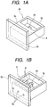
- Figs. 1A and 1B are perspective views which illustrate the ceiling plate of a liquid jet recording head to which the method for manufacturing liquid jet recording heads in accordance with the present invention is applied;
- Fig. 1A is a perspective view which shows the ceiling plate blank integrally formed by means of an injection molding or the like;
- Fig. 1B is a perspective view which shows the ceiling plate having the flow path grooves and the discharge ports formed by processing.
- the ceiling plate blank 2o is provided with the main body portion 2a having the common liquid chamber 2c and the cylindrical protrusion (not shown) having the liquid supply opening 2e which is communicated with the common liquid chamber 2c, and also, with the discharge port plate 2b.
- This is a roughly molded resin product with these parts are integrally formed by known injection molding or the like.
- a plurality of flow path grooves 2f are processed by the irradiation of laser beam onto the flow path processing surface A of the ceiling blank 2o. The flow path grooves 2f thus processed are formed to be communicated with the common liquid chamber 2c as shown in Fig. 1B.
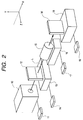
- the laser processing apparatus used for the aforesaid grooving and drilling comprises a laser oscillator 10 that serves as the light source to emit the laser beam L; a controller 11 that changes the oscillation voltages and oscillation frequencies of the laser beam L from the oscillator 10 for application; a mask 12 provided with the opening patterns for grooving and/or drilling; a movement driving device 13 that moves the mask 12 forward or backward (axis X) in the optical axis direction of the laser beam L, and then, in the directions of axes y and Z, and a controller 14 that controls such movement; a projection optical system 15 that projects the opening patterns of the mask 12 onto the processing part of the ceiling plate 2 which is the work W to be processed; a rotation driving device 16 that rotates the projection optical system 15 around the optical axis of the laser beam L; and a controller 17 that controls such rotation.
- a laser oscillator 10 that serves as the light source to emit the laser beam L
- a controller 11 that changes the oscillation voltages and oscillation frequencies
- the ceiling plate 2 which is the work W to be processed is positioned within a plane (Y-Z plane) perpendicular to the optical axis (axis X) of the laser beam L by means of the movement stage 18 which is controlled by use of a controller 19.
- the movement driving device 13 of the mask 12 is provided with a driving mechanism using a stepping motor, a servo motor, or the like. Then, with the controller 14, it is possible to adjust the movement of the mask 12 in the arrangement direction (axis Y) of the opening patterns for use of grooving and/or drilling or in the rotational direction centering on the optical axis of the laser beam L in a precision of micron unit. Also, as to the movement of the mask 12, it is possible to select the continuous movement at a specific speed or the intermittent movements at specific intervals.
- the irradiation of laser beam in a higher energy concentration per hour in order to obtain grooves and holes in desired dimensions at desired pitches, and also, in order to make the discharge ports larger in a shorter period of processing time as possible. For example, if a processing is made with the laser beam energy concentration of 1J/cm 2 per unit hour at the laser oscillation frequency of 200 Hz, it is possible to complete the processing of discharge ports having a large area by the irradiation of laser beam for several seconds.
- the laser beam is irradiated onto the resin blank of the ceiling plate.
- the discharge ports are processed, the byproducts are created eventually.
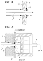
- Fig. 3 is an enlarged view which schematically shows the mode in which a discharge port is processed by the irradiation of laser beam onto the discharge port plate of the ceiling blank.
- a reference mark L designates the laser beam that passes the opening pattern of the mask, and 21, the discharge port plate of the ceiling plate with the water-repellent layer 22 being formed on the liquid discharge surface side before the execution of laser processing.
- the water-repellent agent Cytop (Product name: manufactured by Asahi Glass K.K.) is used. After the Cytop is applied to the discharge port plate 21, the water-repellent layer 22 is formed with heat treatment at 120°C for one hour.
- a reference numeral 23 designates a discharge port formed by the laser processing, and 24, the byproducts adhering to the circumference of the discharge port 23 formed by the laser processing.
- the laser beam L is incident upon the surface of the discharge port plate 21 where no water-repellent layer 22 is formed after having passed the mask.
- the discharge port 23 is processed and formed by ablation made by the irradiation of laser beam.
- a chemical surface modification process is given to the byproducts 24 created following the laser processing, which adhere to the surface where the water-repellent layer 22 is formed on the discharge port plate 21.
- it is intended to suppress the increase of the surface energy of the ceiling plate blank due to the adhesion of the byproducts, thus characteristically preventing the blank surface from becoming hydrophilic.
- the chemical surface modification is given to the byproducts.
- the throughput of the product manufacture is enhanced accordingly, thus making it possible to implement the reduction of manufacture costs.
- the gaseous molecules 26 that contain fluorine atom in its structure are blown to the processing parts, thus forming the resin atmosphere that contains fluorine.
- the nozzle 25 is arranged in the vicinity of the processing part in order to blow the gaseous molecules 26 having the fluorine atom in its structure.
- the discharge ports are processed by the irradiation of laser beam L
- the gaseous molecules 26 that contain fluorine atom in its structure are blown out from the nozzle 25 to the processing parts. In this manner, part of the laser beam L irradiates the gaseous molecules 26 when used for processing.
- the fluorine atom having a higher reaction is created from the gaseous molecules 26.
- the chemical surface modification is made on the byproducts that have been created by the irradiation of laser beam L. It is then attempted to fluorinate the surface of the byproducts. In this way, the chemical modification is performed on the surface of the byproducts that causes the surface energy to rise when adhering to the blank.
- the surface of the byproducts are thus fluorinated so as to suppress the phenomenon that may bring about the local hydrophilicity on the surface of the discharge port plate due to the adhesion of the byproducts.
- this method enables the water-repellency of the related surface to be enhanced more than the conventional art.
- tetrafluoromethane (its molecular formula: CF 4 ), for example.
- CF 4 the molecular formula
- Tetrafluoromethane is a stable gas in the air at the room temperature in its gaseous form. Its handling is easy so that it is easily introduced for use in the manufacture processes of liquid jet recording heads.
- the gas chamber is closely installed on the discharge port surface to blow gas so as to obtain the effect of the fluorination sufficiently at the room temperature under the atmospheric pressure.
- the liquid jet recording head is manufactured, and mounted on a printer to record on a recording sheet with the observation given to the discharged liquid droplets. It is then confirmed that the discharge direction of flying droplets are stabilized with the result that prints are in a better condition as compared with the liquid jet recording head having the byproducts created at the time of discharge port formation but not given any chemical surface modification.
- Fig. 5 is a view which schematically shows the processing mode of the discharge port plate of the ceiling plate processed in accordance with a second embodiment of the present invention.
- the resin having the fluorine atom in its structure is positioned extremely close to the processing part of the blank when it is processed by use of the laser processing apparatus shown in Fig. 2. Then, the laser beam L used for processing is irradiated onto the resin in order to apply the chemical surface modification treatment to the byproducts.
- a reference numeral 27 designates the resin that contains the fluorine atom in its structure, which is positioned extremely close to the processing part of the blank.
- the water-repellent layer 22 is formed on the discharge port plate 21. The laser beam is incident upon from the surface where no water-repellent layer 22 is formed.
- the discharge ports are processed by the irradiation of laser beam L
- part of the laser beam L for use of processing is irradiated onto the resin 27 positioned extremely close to the processing part, which contains the fluorine atom in its structure, so as to create highly reactive fluorine atom from the resin 27.
- the chemical surface modification is given to the byproducts created by the irradiation of laser beam L, thus implementing to fluorinate the surface of the byproducts.
- the chemical surface modification is performed on the byproducts that adheres to the blank surface to raise the surface energy.
- the surface of the byproducts is fluorinated.
- the surface of the discharge port plate is provided with the stabilized water-repellency, hence suppressing the occurrence of the phenomenon in which the hydrophilicity is locally created by the adhesion of the byproducts.
- the irradiation of the laser beam L onto the resin 27 that contains fluorine atom in its structure it becomes possible to partly polymerize the surface of the byproducts again by the resin using the energy of the laser beam L. In this way, the surface of the byproducts is further modified chemically to implement fluorinating the surface thereof.
- the resin that contains fluorine atom in its structure it is possible to use polytetrafluoroethylene, for example.
- polytetrafluoroethylene when the discharge ports are processed by the irradiation of laser beam, polytetrafluoroethylene is positioned extremely close to the processing part of the blank. Then, part of the laser beam L is irradiated onto polytetrafluoroethylene to enable it to create the highly reactive fluorine atom. With this highly reactive fluorine atom, the modification is chemically made on the surface of the byproducts 24, hence attempting to fluorinate the surface thereof. Also, it is possible to implement fluorinating the surface of the byproducts by polymerizing polytetrafluoroethylene again on its surface. Now that polytetrafluoroethylene can be processed into solid in a sheet form at the room temperature under the atmospheric pressure, its handling and procurement are easy so that it is easily introduced for use in the manufacture processes of liquid jet recording heads.
- the resin that contains fluorine atom in its structure in a position on the discharge port surface with a gap of 1 mm or less in order to obtain the sufficient effect of fluorination at the room temperature under the atmospheric pressure.
- the liquid jet recording head is manufactured, and mounted on a printer to record on a recording sheet with the observation given to the discharged liquid droplets. It is then confirmed that the discharge direction of flying droplets are stabilized with the result that prints are made in a better condition as compared with the liquid jet recording head having the byproducts created at the time of discharge port formation but not given any chemical surface modification.
- Fig. 6 is a view which schematically shows the mode of processing the discharge port plate of the ceiling plate in accordance with a third embodiment of the present invention.
- an absorbent such as a sponge, that contains a solution having the polymer containing fluorine atom in its structure as solvent in the solution, is positioned extremely close to the processing part of the blank.
- the laser beam for use of processing is irradiated onto the absorbent to give the chemical surface modification to the byproducts of the laser processing.
- a reference numeral 28 designates the absorbent that contains the solution having the polymer containing the fluorine atom in its structure as solvent in the solution, which is positioned extremely close to the processing part of the blank.
- the water-repellent layer 22 is formed on the discharge port plate 21. The laser beam is incident upon from the surface where no water-repellent layer 22 is formed.
- part of the laser beam L for use of processing is irradiated onto the absorbent 28 that contains polymer having fluorine atom in its structure as solvent in the solution, which is positioned extremely close to the processing part, so as to create highly reactive fluorine atom from the solution having fluorine atom in its structure, which is contained in the absorbent 28.
- the chemical surface modification is given to the byproducts created by the irradiation of laser beam L, thus implementing to fluorinate the surface of the byproducts. In this manner, the chemical surface modification is performed on the byproducts that adheres to the blank surface to raise the surface energy.
- the surface of the byproducts is fluorinated. Then, the surface of the discharge port plate is given the stabilized water-repellency, hence suppressing the occurrence of the phenomenon in which the hydrophilicity is locally created by the adhesion of the byproducts.
- the liquid jet recording head is manufactured, and mounted on a printer to record on a recording sheet with the observation given to the discharged liquid droplets. It is then confirmed that the discharge direction of flying droplets is stabilized with the result that prints are in a better condition as compared with the liquid jet recording head having the byproducts created at the time of discharge port formation but not given any chemical surface modification.
- the present invention it may be possible to combine the blowing of the gaseous molecules with the resin that contains fluorine atom in its structure or with the absorbent that contains the solution having polymer containing fluorine atom as solvent in the solution.
- the chemical surface modification is given to the byproducts that raise the surface energy when adhering to the blank.
- the surface of the byproducts is fluorinated.
- the surface of the discharge port plate shows the stabilized water-repellency, making it possible to suppress the occurrence of the phenomenon in which the hydrophilicity is locally created by the adhesion of the byproducts.
- the liquid jet recording head is manufactured, and mounted on a printer to record on a recording sheet with the observation given to the discharged liquid droplets. It is then confirmed that the discharge direction of flying droplets are stabilized with the result that prints are in a better condition as compared with the liquid jet recording head having the byproducts created at the time of discharge port formation but not given any chemical surface modification.
- the structure is the same as the first embodiment where the gaseous molecules, which contain fluorine atom in its structure, are blown to give the fluorine resin atmosphere to the discharge port plate on the side where the water-repellent layer is formed.
- the ablation processing is made in such a manner that an intermediate reactive substance that may easily react upon the laser beam is positioned extremely close to the processing part on the surface where the water-repellent layer is formed.
- the absorptance of the gaseous molecules that contain fluorine atom in its structure is often smaller with respect to the laser beam.
- the excitation life of the fluorine contained substance CxFy which is activated by the laser beam, is very long.
- the laser beam is irradiated, while gas is blown in a state where the intermediately reactive substance M is arranged. Then, part of the laser beam thus irradiated enables the fluorine contained substance CxFy to be activated directly to create the active seeds CF, CF2, and CF3. These seeds react upon the surface of the discharge port plate to make the surface water-repellent.
- the laser beam is irradiated onto the intermediately reactive substance M.
- the substance M* thus activated collides with the fluorine contained substance CxFy to develop the active seeds CF, CF2, and CF3.
- the intermediately reactive substance M is the substance that can absorb the laser beam easily, and its active life is longer. As a result, there is an extremely high probability that this substance can collide with the fluorine contained substance CxFy.
- the active seeds CF, CF2, and CF3 thus formed react upon the surface of the discharge port plate as in the previous case.
- the active substance M* that has collided with the fluorine contained substance CxFy loses its energy, and returns to the basic state of M.
- the excimer laser is used for processing as a coherent laser source in order to process the discharge ports by means of ablation at a time by use of the laser processing apparatus shown in Fig. 2.
- the excimer laser is the laser capable of oscillating ultraviolet beam. It has a good monochromaticity with a higher intensity, as well as a good directivity. Therefore, it can be oscillated in short pulses, and has an advantage, among many others, that when it is converged by use of lens, the energy concentration is made extremely great.
- the excimer laser oscillator is an apparatus that can oscillate ultraviolet beam in short pulses (15 to 35 ns) by discharging the mixed gas of rare gas and halogen for its excitation, and often uses Kr-F laser, Xe-C1 laser, or Ar-F laser.
- the oscillated energy of such laser is several hundreds of mj/pulse, and the pulse repetition frequency is 30 to 1,000 Hz.
- KrF laser which is excimer laser beam
- KrF laser is used to process the discharge ports at a time by means of ablation.
- liquid jet recording heads capable of printing in high quality with the stabilized discharge directivity of flying droplets by the utilization of excellent characteristics of excimer laser when used for a processing of the kind.
- the present invention demonstrates an excellent effect with respect to the recording head and recording apparatus of the so-called ink jet recording type, which performs recording by forming flying droplets particularly by the utilization of thermal energy among those liquid jet recording methods.
- discharge signals are supplied from a driving circuit to electrothermal transducing elements, which serve as discharge energy generating elements, disposed on a liquid (ink) retaining sheet or liquid path.
- at least one driving signal is given in order to provide recording liquid (ink) with a rapid temperature rise so that film boiling phenomenon, which is beyond nuclear boiling phenomenon, is created in the liquid, thus generating thermal energy to cause film boiling on the thermoactive surface of the recording head. Since a bubble can be formed from the recording liquid (ink) by means of the driving signal given to an electrothermal converting element one to one, this method is effective particularly for the on-demand type recording method.
- the liquid (ink) is discharged through each discharge port to produce at least one droplet.
- the driving signal is more preferably in the form of pulses because the development and contraction of the bubble can be effectuated instantaneously and appropriately.
- the liquid (ink) is discharged with quicker response.
- the driving signal in the form of pulses is preferably such as disclosed in the specifications of U.S. Patent Nos. 4,463,359 and 4,345,262.
- the temperature increasing rate of the thermoactive surface is preferably such as disclosed in the specification of U.S. Patent No. 4,313,124 for an excellent recording in a better condition.
- the present invention is effectively applicable to those which are shown in each of the above-mentioned specifications wherein the structure is arranged to combine the discharging openings, liquid paths, and the electrothermal converting elements (linear type liquid paths or right-angled liquid paths). Besides, it is equally and effectively applicable to the structure such as disclosed in the specifications of U.S. Patent Nos. 4,558,333 and 4,459,600 in which the thermal activation portions are arranged in a curved area.
- the present invention is effectively applicable to the structure disclosed in Japanese Patent Application Laid-Open No. 59-123670 wherein a common slit is used as the discharging ports for plural electrothermal transducing elements, and to the structure disclosed in Japanese Patent Application Laid-Open No. 59-138461 wherein an aperture for absorbing pressure waves of thermal energy is formed corresponding to the discharge ports.
- the full-line type recording head whose length corresponds to the maximum width of a recording medium recordable by such recording apparatus.
- the full-line type recording head it may be possible to adopt either a structure whereby to satisfy the required length by combining a plurality of recording heads or a structure arranged by one recording head integrally formed.
- the present invention is effectively applicable to an exchangeable recording head of a chip type that can be electrically connected with the apparatus main body, the ink supply therefor being made possible from the apparatus main body, when mounted on the apparatus main body or to the use of a cartridge type recording head provided integrally for the recording head itself.
- a recording head with recovery means and preliminarily auxiliary means because these additional means will contribute to making the effectiveness of a recording apparatus more stabilized.
- these additional means are capping means, cleaning means, suction or compression means, preheating means such as electrothermal converting elements or heating devices other than such transducing devices or the combination of those types of devices, and a predischarge means for performing discharge other than the regular discharge with respect to the recording head.
- the present invention is not only applicable to a recording mode in which only one main color such as black is used for recording, but also, the invention is extremely effective in applying it to an apparatus having plural recording heads provided for use of at least one of multiple colors prepared by different colors or full-color prepared by mixing colors, irrespective of whether the recording heads are integrally structured or structured by a combination of plural recording heads.
- the ink has been described as liquid, it may be an ink material which is solidified below the room temperature but soften or liquefied at the room temperature or soften or liquefied within a temperature range of the temperature adjustment generally practiced for an ink jet recording, that is, not lower than 30°C but not higher than 70°C. In other words, it should be good enough if only ink is liquefied at the time of giving recording signals for use.
- an ink having a nature of being liquefied only by the application of thermal energy such as an ink capable of being discharged as ink liquid by enabling itself to be liquefied anyway when the thermal energy is given in accordance with recording signals, and an ink which will have already begun solidifying itself by the time it reaches a recording medium.
- ink in the form of liquid or solid in the recesses or through holes of a porous sheet such as disclosed in Japanese Patent Application Laid-Open Nos. 54-56847 or 60-71260 in order to enable the ink to face the electrothermal converting elements.
- the most effective method for the various kinds of ink mentioned above is the one that enables the film boiling method to be effectuated as described above.
- the mode of the recording apparatus described above it may be possible to adopt a copying apparatus combined with a reader, in addition to the image output terminal for a computer or other information processing apparatus. Also, for the recording apparatus described above, it may be possible to adopt a mode of a facsimile equipment provided with transmitting and receiving functions.
- liquid jet recording heads there is no need for the provision of any special processes in order to remove the byproducts adhering to the ceiling plate. Therefore, in the manufacture of liquid jet recording heads, it also becomes possible to solve the problem encountered in the conventional art that the product throughput is considerably lowered. With the solution of such problem, liquid jet recording heads can be manufactured at lower costs with a good product throughput.
- a method for manufacturing liquid jet recording heads, each provided with discharge ports to discharge liquid, a discharge port plate having the discharge ports arranged therefor, and performing ablation processing of holes becoming the discharge ports by use of a mask for projecting the image of the mask onto the discharge port plate with coherent laser beam as light source comprises the following steps of forming water-repellent layer on the surface of the discharge port plate on the liquid discharge side; and of performing the ablation processing by irradiating the laser beam from the reverse side of the surface of discharge port plate having the water-repellent layer formed thereon in a state of such surface being arranged to be under the atmosphere containing fluorine atom, and forming the discharge ports, at the same time, enabling the substance containing the fluorine atom excited by the laser beam to adhere to the surface having the water-repellent layer formed thereon.
- the throughput of product manufacture is enhanced without any provision of extra processing steps to remove the byproducts to be created by the irradiation of laser beam, hence contributing to a significant cost reduction of the manufacture of
Landscapes
- Engineering & Computer Science (AREA)
- Manufacturing & Machinery (AREA)
- Physics & Mathematics (AREA)
- Optics & Photonics (AREA)
- Particle Formation And Scattering Control In Inkjet Printers (AREA)
Applications Claiming Priority (3)
| Application Number | Priority Date | Filing Date | Title |
|---|---|---|---|
| JP246062/97 | 1997-08-27 | ||
| JP24606297 | 1997-08-27 | ||
| JP24606297 | 1997-08-27 |
Publications (3)
| Publication Number | Publication Date |
|---|---|
| EP0900660A2 true EP0900660A2 (fr) | 1999-03-10 |
| EP0900660A3 EP0900660A3 (fr) | 1999-09-15 |
| EP0900660B1 EP0900660B1 (fr) | 2003-12-03 |
Family
ID=17142912
Family Applications (1)
| Application Number | Title | Priority Date | Filing Date |
|---|---|---|---|
| EP98116118A Expired - Lifetime EP0900660B1 (fr) | 1997-08-27 | 1998-08-26 | Procédé de fabrication de têtes d'impression à jet de liquide et tête obtenue par ce procédé |
Country Status (4)
| Country | Link |
|---|---|
| US (1) | US6225032B1 (fr) |
| EP (1) | EP0900660B1 (fr) |
| DE (1) | DE69820176T2 (fr) |
| ES (1) | ES2210631T3 (fr) |
Families Citing this family (3)
| Publication number | Priority date | Publication date | Assignee | Title |
|---|---|---|---|---|
| EP1132058A1 (fr) * | 2000-03-06 | 2001-09-12 | Advanced Laser Applications Holding S.A. | Prothèse intravasculaire |
| SG128447A1 (en) * | 2002-09-30 | 2007-01-30 | Asml Netherlands Bv | Lithographic apparatus and device manufacturing method |
| KR20130139265A (ko) * | 2010-10-13 | 2013-12-20 | 도쿄엘렉트론가부시키가이샤 | 템플레이트 및 기판의 처리 방법 |
Family Cites Families (21)
| Publication number | Priority date | Publication date | Assignee | Title |
|---|---|---|---|---|
| DE1621355A1 (de) | 1967-06-09 | 1971-05-13 | Steigerwald Strahltech | Verfahren zur Behandlung der Innenflaechen von Bohrungen in Werkstuecken |
| US3866398A (en) | 1973-12-20 | 1975-02-18 | Texas Instruments Inc | In-situ gas-phase reaction for removal of laser-scribe debris |
| CA1127227A (fr) | 1977-10-03 | 1982-07-06 | Ichiro Endo | Procede d'enregistrement a jet liquide et appareil d'enregistrement |
| JPS5936879B2 (ja) | 1977-10-14 | 1984-09-06 | キヤノン株式会社 | 熱転写記録用媒体 |
| US4330787A (en) | 1978-10-31 | 1982-05-18 | Canon Kabushiki Kaisha | Liquid jet recording device |
| US4345262A (en) | 1979-02-19 | 1982-08-17 | Canon Kabushiki Kaisha | Ink jet recording method |
| US4463359A (en) | 1979-04-02 | 1984-07-31 | Canon Kabushiki Kaisha | Droplet generating method and apparatus thereof |
| US4313124A (en) | 1979-05-18 | 1982-01-26 | Canon Kabushiki Kaisha | Liquid jet recording process and liquid jet recording head |
| US4558333A (en) | 1981-07-09 | 1985-12-10 | Canon Kabushiki Kaisha | Liquid jet recording head |
| JPS59123670A (ja) | 1982-12-28 | 1984-07-17 | Canon Inc | インクジエツトヘツド |
| JPS59138461A (ja) | 1983-01-28 | 1984-08-08 | Canon Inc | 液体噴射記録装置 |
| JPS6071260A (ja) | 1983-09-28 | 1985-04-23 | Erumu:Kk | 記録装置 |
| JP2660243B2 (ja) * | 1985-08-08 | 1997-10-08 | 株式会社半導体エネルギー研究所 | 半導体装置作製方法 |
| ATE210019T1 (de) | 1990-07-21 | 2001-12-15 | Canon Kk | Herstellungsverfahren eines farbstrahlaufzeichnungskopfes und farbstrahlaufzeichnungskopf |
| JP2791226B2 (ja) | 1991-03-08 | 1998-08-27 | キヤノン株式会社 | 記録ヘッドの製造方法および記録ヘッド |
| JP3095795B2 (ja) | 1991-01-18 | 2000-10-10 | キヤノン株式会社 | インクジェット記録ヘッドおよび該ヘッドの製造方法 |
| US5103284A (en) * | 1991-02-08 | 1992-04-07 | Energy Conversion Devices, Inc. | Semiconductor with ordered clusters |
| JPH05116325A (ja) * | 1991-10-30 | 1993-05-14 | Canon Inc | インクジエツト記録ヘツドの製造方法 |
| JP3196796B2 (ja) | 1992-06-24 | 2001-08-06 | セイコーエプソン株式会社 | インクジェット記録ヘッドのノズル形成方法 |
| DK121994A (da) | 1994-05-03 | 1995-11-04 | Ferroperm Components As | Fremgangsmåde til bearbejdning af oxidmaterialer ved hjælp af en laserstråle |
| US5576925A (en) * | 1994-12-27 | 1996-11-19 | General Electric Company | Flexible multilayer thin film capacitors |
-
1998
- 1998-08-25 US US09/139,399 patent/US6225032B1/en not_active Expired - Fee Related
- 1998-08-26 ES ES98116118T patent/ES2210631T3/es not_active Expired - Lifetime
- 1998-08-26 EP EP98116118A patent/EP0900660B1/fr not_active Expired - Lifetime
- 1998-08-26 DE DE69820176T patent/DE69820176T2/de not_active Expired - Fee Related
Also Published As
| Publication number | Publication date |
|---|---|
| DE69820176D1 (de) | 2004-01-15 |
| DE69820176T2 (de) | 2004-09-30 |
| EP0900660A3 (fr) | 1999-09-15 |
| ES2210631T3 (es) | 2004-07-01 |
| US6225032B1 (en) | 2001-05-01 |
| EP0900660B1 (fr) | 2003-12-03 |
Similar Documents
| Publication | Publication Date | Title |
|---|---|---|
| USRE38710E1 (en) | Laser process for making a filter for an ink jet | |
| EP0500068B1 (fr) | Tête d'enregistrement à jet d'encre, appareil d'enregistrement l'utilisant et méthode pour sa fabrication | |
| US6423934B2 (en) | Method for forming through holes | |
| JPH0624874B2 (ja) | インクジェットプリンタ用ノズル | |
| JP3305041B2 (ja) | インクジェットヘッド、その製造方法および前記インクジェットヘッドを備えたインクジェット装置 | |
| EP0900660B1 (fr) | Procédé de fabrication de têtes d'impression à jet de liquide et tête obtenue par ce procédé | |
| JP2633943B2 (ja) | インクジェット記録ヘッドおよび該ヘッドの製造方法 | |
| JP3183033B2 (ja) | インク噴射装置のノズルプレートの製造方法 | |
| JP3095795B2 (ja) | インクジェット記録ヘッドおよび該ヘッドの製造方法 | |
| US8869401B2 (en) | Method for manufacturing microstructure, and method for manufacturing liquid jetting head | |
| JPH05330046A (ja) | 液体記録ヘッド及び液体記録ヘッドの製造方法 | |
| JPH11138822A (ja) | 液体噴射記録ヘッドの製造方法および該製造方法により製造された液体噴射記録ヘッド | |
| JPH11188882A (ja) | 液体噴射記録ヘッドおよびその製造方法 | |
| US6668454B2 (en) | Method for manufacturing a liquid-discharging recording head | |
| JP3086146B2 (ja) | インクジェット記録ヘッドおよびその製造方法、レーザ加工装置ならびにインクジェット記録装置 | |
| EP0786305B1 (fr) | Appareil d'usinage au laser et méthode de fabrication de tête d'enregistrement par jet de liquide au moyen d'un tel appareil d'usinage au laser | |
| JPH106514A (ja) | インクジェット記録ヘッドの製造方法、該方法による記録ヘッド、及び該ヘッドを具備するインクジェット記録装置 | |
| JP3122195B2 (ja) | インクジェット記録ヘッド、その製造方法および前記インクジェット記録ヘッドを備えたインクジェット記録装置 | |
| JPH0592569A (ja) | 液体噴射記録ヘツド及びその製造方法 | |
| JPH09234874A (ja) | インクジェット記録ヘッドの製造方法、該方法により製造されるインクジェット記録ヘッド及び該記録ヘッドを具備した記録装置 | |
| JPH0752392A (ja) | ノズル形成方法 | |
| JP3198219B2 (ja) | インクジェット記録ヘッドおよびインクジェット記録装置 | |
| JPH06312508A (ja) | インクジェット記録ヘッド、インクジェット記録ヘッドの製造方法および前記インクジェット記録ヘッドを備えたインクジェット記録装置 | |
| JPH05124197A (ja) | インクジエツト記録ヘツドおよびその製造方法 | |
| JPH06226984A (ja) | 液体噴射記録ヘッドの製造方法および液体噴射記録ヘッド |
Legal Events
| Date | Code | Title | Description |
|---|---|---|---|
| PUAI | Public reference made under article 153(3) epc to a published international application that has entered the european phase |
Free format text: ORIGINAL CODE: 0009012 |
|
| AK | Designated contracting states |
Kind code of ref document: A2 Designated state(s): DE ES FR GB IT NL |
|
| AX | Request for extension of the european patent |
Free format text: AL;LT;LV;MK;RO;SI |
|
| PUAL | Search report despatched |
Free format text: ORIGINAL CODE: 0009013 |
|
| AK | Designated contracting states |
Kind code of ref document: A3 Designated state(s): AT BE CH CY DE DK ES FI FR GB GR IE IT LI LU MC NL PT SE |
|
| AX | Request for extension of the european patent |
Free format text: AL;LT;LV;MK;RO;SI |
|
| RIC1 | Information provided on ipc code assigned before grant |
Free format text: 6B 41J 2/16 A, 6B 23K 26/12 B, 6B 23K 26/00 B |
|
| 17P | Request for examination filed |
Effective date: 20000128 |
|
| AKX | Designation fees paid |
Free format text: DE ES FR GB IT NL |
|
| GRAH | Despatch of communication of intention to grant a patent |
Free format text: ORIGINAL CODE: EPIDOS IGRA |
|
| RAP1 | Party data changed (applicant data changed or rights of an application transferred) |
Owner name: CANON KABUSHIKI KAISHA |
|
| GRAS | Grant fee paid |
Free format text: ORIGINAL CODE: EPIDOSNIGR3 |
|
| GRAA | (expected) grant |
Free format text: ORIGINAL CODE: 0009210 |
|
| AK | Designated contracting states |
Kind code of ref document: B1 Designated state(s): DE ES FR GB IT NL |
|
| REG | Reference to a national code |
Ref country code: GB Ref legal event code: FG4D |
|
| REF | Corresponds to: |
Ref document number: 69820176 Country of ref document: DE Date of ref document: 20040115 Kind code of ref document: P |
|
| REG | Reference to a national code |
Ref country code: ES Ref legal event code: FG2A Ref document number: 2210631 Country of ref document: ES Kind code of ref document: T3 |
|
| ET | Fr: translation filed | ||
| PLBE | No opposition filed within time limit |
Free format text: ORIGINAL CODE: 0009261 |
|
| STAA | Information on the status of an ep patent application or granted ep patent |
Free format text: STATUS: NO OPPOSITION FILED WITHIN TIME LIMIT |
|
| 26N | No opposition filed |
Effective date: 20040906 |
|
| PGFP | Annual fee paid to national office [announced via postgrant information from national office to epo] |
Ref country code: NL Payment date: 20080819 Year of fee payment: 11 Ref country code: ES Payment date: 20080704 Year of fee payment: 11 Ref country code: DE Payment date: 20080831 Year of fee payment: 11 |
|
| PGFP | Annual fee paid to national office [announced via postgrant information from national office to epo] |
Ref country code: IT Payment date: 20080820 Year of fee payment: 11 Ref country code: FR Payment date: 20080821 Year of fee payment: 11 |
|
| PGFP | Annual fee paid to national office [announced via postgrant information from national office to epo] |
Ref country code: GB Payment date: 20080814 Year of fee payment: 11 |
|
| REG | Reference to a national code |
Ref country code: NL Ref legal event code: V1 Effective date: 20100301 |
|
| GBPC | Gb: european patent ceased through non-payment of renewal fee |
Effective date: 20090826 |
|
| REG | Reference to a national code |
Ref country code: FR Ref legal event code: ST Effective date: 20100430 |
|
| PG25 | Lapsed in a contracting state [announced via postgrant information from national office to epo] |
Ref country code: NL Free format text: LAPSE BECAUSE OF NON-PAYMENT OF DUE FEES Effective date: 20100301 Ref country code: FR Free format text: LAPSE BECAUSE OF NON-PAYMENT OF DUE FEES Effective date: 20090831 Ref country code: DE Free format text: LAPSE BECAUSE OF NON-PAYMENT OF DUE FEES Effective date: 20100302 |
|
| REG | Reference to a national code |
Ref country code: ES Ref legal event code: FD2A Effective date: 20090827 |
|
| PG25 | Lapsed in a contracting state [announced via postgrant information from national office to epo] |
Ref country code: GB Free format text: LAPSE BECAUSE OF NON-PAYMENT OF DUE FEES Effective date: 20090826 |
|
| PG25 | Lapsed in a contracting state [announced via postgrant information from national office to epo] |
Ref country code: IT Free format text: LAPSE BECAUSE OF NON-PAYMENT OF DUE FEES Effective date: 20090826 |
|
| PG25 | Lapsed in a contracting state [announced via postgrant information from national office to epo] |
Ref country code: ES Free format text: LAPSE BECAUSE OF NON-PAYMENT OF DUE FEES Effective date: 20090827 |