EP0900903B1 - Vorrichtung zur Sicherung von Artikeln gegen Diebstahl, entsprechendes Herstellungsverfahren und Vorrichtung zur Durchführung des Verfahrens - Google Patents
Vorrichtung zur Sicherung von Artikeln gegen Diebstahl, entsprechendes Herstellungsverfahren und Vorrichtung zur Durchführung des Verfahrens Download PDFInfo
- Publication number
- EP0900903B1 EP0900903B1 EP98114681A EP98114681A EP0900903B1 EP 0900903 B1 EP0900903 B1 EP 0900903B1 EP 98114681 A EP98114681 A EP 98114681A EP 98114681 A EP98114681 A EP 98114681A EP 0900903 B1 EP0900903 B1 EP 0900903B1
- Authority
- EP
- European Patent Office
- Prior art keywords
- housing
- security element
- strip
- rotary part
- wire material
- Prior art date
- Legal status (The legal status is an assumption and is not a legal conclusion. Google has not performed a legal analysis and makes no representation as to the accuracy of the status listed.)
- Expired - Lifetime
Links
Images

Classifications
-
- G—PHYSICS
- G08—SIGNALLING
- G08B—SIGNALLING SYSTEMS, e.g. PERSONAL CALLING SYSTEMS; ORDER TELEGRAPHS; ALARM SYSTEMS
- G08B13/00—Burglar, theft or intruder alarms
- G08B13/22—Electrical actuation
- G08B13/24—Electrical actuation by interference with electromagnetic field distribution
- G08B13/2402—Electronic Article Surveillance [EAS], i.e. systems using tags for detecting removal of a tagged item from a secure area, e.g. tags for detecting shoplifting
- G08B13/2428—Tag details
- G08B13/2434—Tag housing and attachment details
-
- E—FIXED CONSTRUCTIONS
- E05—LOCKS; KEYS; WINDOW OR DOOR FITTINGS; SAFES
- E05B—LOCKS; ACCESSORIES THEREFOR; HANDCUFFS
- E05B73/00—Devices for locking portable objects against unauthorised removal; Miscellaneous locking devices
- E05B73/0017—Anti-theft devices, e.g. tags or monitors, fixed to articles, e.g. clothes, and to be removed at the check-out of shops
-
- G—PHYSICS
- G08—SIGNALLING
- G08B—SIGNALLING SYSTEMS, e.g. PERSONAL CALLING SYSTEMS; ORDER TELEGRAPHS; ALARM SYSTEMS
- G08B13/00—Burglar, theft or intruder alarms
- G08B13/22—Electrical actuation
- G08B13/24—Electrical actuation by interference with electromagnetic field distribution
- G08B13/2402—Electronic Article Surveillance [EAS], i.e. systems using tags for detecting removal of a tagged item from a secure area, e.g. tags for detecting shoplifting
- G08B13/2428—Tag details
- G08B13/2437—Tag layered structure, processes for making layered tags
- G08B13/244—Tag manufacturing, e.g. continuous manufacturing processes
Definitions
- the invention relates to a device for securing Anti-theft articles, with a housing, with a securing element arranged in the housing, that is a self-contained form has, and with a magnetic trained fastening mechanism, which has a releasable pin with which the device to be secured Articles, e.g. a piece of clothing, is attachable. Furthermore, the invention relates to a method for the production of the device according to the invention.
- a device is already from the prior art - a so-called hard day - became known, which consists of two in there are essentially identical halves.
- On the A strip element is made from the inside of one half glued on soft magnetic material. Then be the two halves put together, and the hard tag will be by means of a releasable pin on one to be secured Article, for example attached to a piece of clothing.
- the fuse element is a detectable Response signal sends out, the soft magnetic strip or the soft magnetic wire a certain length exhibit. Because a hard day has its largest diameter in Has the central area, the stripe elements therefore run in the middle range.
- This arrangement prepares from the following Reasonable problems: Usually the Fastening mechanism designed magnetically, for Loosen the fastening pin from the item relatively high Magnetic fields are required.
- An example of one such fastening mechanism is e.g. from EP 0 132 531 B1 became known.
- From US-A-4 751 500 is also a device for Securing items against theft in the form of a so-called "Hard Tags" known.
- This consists of a housing in which a locking mechanism is arranged in which a pin a fastener can detachably snap. That too arranged in the housing fuse element consists of a spiral wound coil with a capacitor too an electrical resonant circuit is connected.
- the invention has for its object a device with an electronic propose detectable fuse element that itself is characterized by a high detection rate and cannot be influenced by a magnetic fastening mechanism. Still lies the invention has for its object an inexpensive Device manufacturing process imagine.
- the strip is due to the curved, in itself closed form so long that it is sufficiently strong Response signal to an external magnetic field. Furthermore, the securing element is so far from that Mounting mechanism removes that its magnetic Condition due to stray fields of the locking mechanism is adversely affected.
- the Fixing mechanism for hard tags usually works up magnetic base. To detach the hard tags from the Secured items are relatively high magnetic fields required. These fields usually magnetize the magnetic locking mechanism, which in turn a nearby security element via a stray field negatively influenced. To prevent this from happening, the device according to the invention the distance of the securing element from that Fastening mechanism chosen as possible. Because of the great distance from that Attachment mechanism will change the magnetic state of the Security element not or hardly by stray fields of the Locking mechanism affected. Third is the detection rate especially with a circular configuration of the Securing element regardless of the orientation to outer field.
- the device provides that the securing element is in one piece is formed or that it consists of at least two individual elements consists. It has it turned out that the arrangement of the individual elements there is essentially nothing in the gap Functionality of the device according to the invention changes.
- the housing consists of at least two parts.
- the following advantageous embodiment is in the housing suggested: there is one on the inside of the housing circular or elliptical guidance provided on which the securing element lies on.
- the guide can be a groove or a Survey acts, the survey as a continuous or interrupted bead can be formed.
- the securing element is at least on one of the two parts of the housing fixed at certain points.
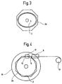
- the object is achieved with regard to the method for producing the device according to the invention solved that one of the two parts of the housing is mounted on a rotary unit, that a securing element a dispensing device that the rotating part of the Housing is assigned in Form of soft magnetic strip or wire material is provided and that the strip or wire material during rotation of the rotating unit in a self-contained form in the housing is introduced that it is placed in a ring on the inside of the rotating part of the housing.
- the method proposes that by means of a cutting device, which is assigned to the dispensing device, the tape material is provided in a desired length. It is also provided that the Securing element by means of an adhesive device at least at certain points on the rotating part of the Housing is attached.
- the dispensing device is placed in such a way that the securing element in an annular on the inside of the rotating part of the housing or other self-contained structure.
- Fig. 1 shows a plan view of a first embodiment of the device according to the invention in the unassembled state.
- the device 1 consists of two essentially identical halves 2a, 2b which are firmly connected to one another in the assembled state.
- the device 1 is fastened to an article to be secured via the fastening mechanism 4.
- the securing element 3 is arranged according to the invention in a self-contained form. In the case shown, the shape is a circle.
- the securing element 3 consists of one part. Rather, it can consist of a plurality of sub-elements 3a arranged on a gap from one another.
- This configuration considerably simplifies the assembly of the securing element 3 in the device according to the invention. As can be seen in FIG. 2, it is sufficient to fix the securing element 3 if the guide consists of individual projecting elements.
- the securing element 3 is a strip or Wire material 8 wound on a supply roll 13 and is successively provided by the dispensing device 9.
- the beginning of the strip or wire material 8 is in a clamping part 14 fixed on the housing part 2a and during the subsequent rotating process of the rotary unit 10 circular or in the desired shape on the Housing part 2a placed. Is it the stripe or Wire material 8 around a strip material, so this lies with the edge on the housing part 2a and with the flat side at the guide 5.
- a fixation of the securing element 3 on the guide 5 or the housing part 2a is carried out by means of an adhesive donated by the gluing device 12.
- the Strip or wire material 8 is made by means of one of the dispensing devices 9 assigned cutting device 11 provided in the desired length.
Landscapes
- Physics & Mathematics (AREA)
- Engineering & Computer Science (AREA)
- Automation & Control Theory (AREA)
- Computer Security & Cryptography (AREA)
- Electromagnetism (AREA)
- General Physics & Mathematics (AREA)
- Manufacturing & Machinery (AREA)
- Burglar Alarm Systems (AREA)
- Control Of Vending Devices And Auxiliary Devices For Vending Devices (AREA)
- Packaging For Recording Disks (AREA)
Description
- senkrecht zur Vorzugsachse des Sicherungselements einfällt. Um die Detektionswahrscheinlichkeit zu erhöhen, werden im
- Stand der Technik daher zwei Streifenelemente kreuzförmig zueinander orientiert.
Auf der Innenseite einer der beiden Gehäuseteile 2a; 2b ist erfindungsgemäß das Sicherungselement 3 in einer in sich geschlossenen Form angeordnet. Im dargestellten Fall handelt es sich bei der Form um einen Kreis. Wie aus Fig. 2 zu ersehen, ist es nicht erforderlich, daß das Sicherungselement 3 aus einem Teil besteht. Vielmehr kann es aus mehreren voneinander auf Lücke angeordneten Teilelementen 3a bestehen. Zwecks Fixierung des Sicherungselements 3 bzw. der Teilelemente 3a ist eine Führung 5, entweder eine Nut 6 oder eine Erhebung (Wulst 7) (Fig. 3), vorgesehen. Durch diese Ausgestaltung wird die Montage des Sicherungselements 3 in der erfindungsgemäßen Vorrichtung wesentlich vereinfacht. Zur Fixierung des Sicherungselements 3 reicht es -wie in Fig. 2 zu sehen- aus, wenn die Führung aus einzelnen vorstehenden Elementen besteht.
- 1
- erfindungsgemäße Vorrichtung
- 2
- Gehäuse
- 2a
- erster Gehäuseteil
- 2b
- zweiter Gehäuseteil
- 3
- Sicherungselement
- 3a
- Einzelelement
- 4
- Befestigungsmechanismus
- 5
- Führung
- 6
- Nut
- 7
- Wulst
- 8
- Streifen-oder Bandmaterial
- 9
- Spendevorrichtung
- 10
- Rotationseinheit
- 11
- Schneidevorrichtung
- 12
- Klebevorrichtung
- 13
- Vorratsrolle
Claims (10)
- Vorrichtung zur Sicherung von Artikeln gegen Diebstahl,
mit einem Gehäuse,
mit einem in dem Gehäuse angeordneten Sicherungselement, das eine in sich geschlossene Form aufweist, und
mit einem magnetisch ausgebildeten Befestigungsmechanismus, der einen lösbaren Stift aufweist, mit dem die Vorrichtung an einem zu sichernden Artikel, z.B. einem Kleidungsstück, befestigbar ist,
dadurch gekennzeichnet, dass das Sicherungselement (3) ein kreisförmig oder elliptisch ausgebildeter Streifen oder Draht aus weichmagnetischem Material ist und in einem maximal möglichen Abstand um den Befestigungsmechanismus (4) angeordnet ist. - Vorrichtung nach Anspruch 1,
dadurch gekennzeichnet, dass das Sicherungselement (3) einteilig ausgebildet ist oder aus zumindest zwei Einzelelementen (3a) besteht. - Vorrichtung nach Anspruch 1 oder 2,
dadurch gekennzeichnet, dass das Gehäuse (2) aus zumindest zwei Teilen (2a, 2b) besteht. - Vorrichtung nach Anspruch 3,
dadurch gekennzeichnet, dass auf einer Innenseite des Gehäuses (2) eine ringförmige oder elliptische Führung (5) vorgesehen ist, an der das Sicherungselement (3) anliegt. - Vorrichtung nach Anspruch 4,
dadurch gekennzeichnet, dass es sich bei der Führung (5) um eine Nut (6) oder eine Erhebung handelt, wobei die Erhebung als durchgehender oder unterbrochener Wulst (7) ausgebildet ist. - Vorrichtung nach einem der Ansprüche 3 bis 5,
dadurch gekennzeichnet, dass das Sicherungselement (3) an einem der beiden Teile (2a; 2b) des Gehäuses (2) zumindest punktuell befestigt ist. - Verfahren zur Herstellung einer Vorrichtung nach einem der Ansprüche 3 bis 6,
dadurch gekennzeichnet, dass eines der beiden Teile (2a; 2b) des Gehäuses auf einer Rotationseinheit (10) gelagert wird,
dass ein Sicherungselement (3) mittels einer Spendevorrichtung (9), die dem rotierenden Teil (2a; 2b) des Gehäuses (2) zugeordnet ist, in Form von weichmagnetischem Streifen- oder Drahtmaterial (8) bereitgestellt wird, und
dass das Streifen- oder Drahtmaterial (8) während einer Rotation der Rotationseinheit (10) in einer in sich geschlossenen Form derart in das Gehäuse (2) eingebracht wird, dass es ringförmig auf der Innenseite des rotierenden Teils (2a) des Gehäuses (2) platziert wird. - Verfahren nach Anspruch 7,
dadurch gekennzeichnet, dass mittels einer Schneidevorrichtung (11), die der Spendevorrichtung (9) zugeordnet ist, das Streifen-oder Drahtmaterial (8) in einer gewünschten Länge (1) bereitgestellt wird. - Verfahren nach Anspruch 7 oder 8,
dadurch gekennzeichnet, dass das Sicherungselement (3) mittels einer Klebevorrichtung (12) zumindest punktuell an dem rotierenden Teil (2a) des Gehäuses (2) befestigt wird. - Verfahren nach einem der Ansprüche 7 bis 9,
dadurch gekennzeichnet, dass die Spendevorrichtung (9) derart platziert wird, dass sie das Sicherungselement (3) in einer an der Innenseite des rotierenden Teiles (2a) des Gehäuses (2) aufgebrachten ringförmigen oder anderen in sich geschlossenen Struktur ausrichtet.
Applications Claiming Priority (2)
| Application Number | Priority Date | Filing Date | Title |
|---|---|---|---|
| DE19738309 | 1997-09-02 | ||
| DE19738309A DE19738309A1 (de) | 1997-09-02 | 1997-09-02 | Vorrichtung zur Sicherung von Artikeln gegen Diebstahl, entsprechendes Herstellungsverfahren und Vorrichtung zur Durchführung des Verfahrens |
Publications (3)
| Publication Number | Publication Date |
|---|---|
| EP0900903A2 EP0900903A2 (de) | 1999-03-10 |
| EP0900903A3 EP0900903A3 (de) | 1999-11-10 |
| EP0900903B1 true EP0900903B1 (de) | 2004-05-12 |
Family
ID=7840954
Family Applications (1)
| Application Number | Title | Priority Date | Filing Date |
|---|---|---|---|
| EP98114681A Expired - Lifetime EP0900903B1 (de) | 1997-09-02 | 1998-08-05 | Vorrichtung zur Sicherung von Artikeln gegen Diebstahl, entsprechendes Herstellungsverfahren und Vorrichtung zur Durchführung des Verfahrens |
Country Status (5)
| Country | Link |
|---|---|
| EP (1) | EP0900903B1 (de) |
| AT (1) | ATE266787T1 (de) |
| DE (2) | DE19738309A1 (de) |
| DK (1) | DK0900903T3 (de) |
| ES (1) | ES2217466T3 (de) |
Cited By (1)
| Publication number | Priority date | Publication date | Assignee | Title |
|---|---|---|---|---|
| US9466233B2 (en) | 2008-09-04 | 2016-10-11 | Avery Dennison Retail Information Services, Llc | Antifraud device for garments and other consumer products and devices and system and method related thereto |
Family Cites Families (8)
| Publication number | Priority date | Publication date | Assignee | Title |
|---|---|---|---|---|
| US4187509A (en) * | 1977-06-20 | 1980-02-05 | Knogo Corporation | Wafer and fastener for use in electronic theft detection system |
| US4531264A (en) | 1983-07-27 | 1985-07-30 | Knogo Corporation | Theft detection system target fastener |
| DE8403075U1 (de) * | 1984-02-03 | 1984-05-17 | Deutsche Vitrohm Gmbh & Co Kg, 2080 Pinneberg | An gegenstaenden anbringbare marke fuer ein diebstahlsicherungssystem |
| US4751500A (en) * | 1987-02-10 | 1988-06-14 | Knogo Corporation | Detection of unauthorized removal of theft detection target devices |
| US4774503A (en) * | 1987-06-22 | 1988-09-27 | Monarch Marking Systems, Inc. | Anti-theft tag |
| DE4242992B4 (de) * | 1992-12-18 | 2004-01-29 | Meto International Gmbh | Anordnung zur Sicherung eines Artikels, insbesondere einer Aufzeichnungsplatte wie eine CD-Platte |
| AU667431B2 (en) * | 1993-06-11 | 1996-03-21 | Sensormatic Electronics Corporation | Multidirectional surveillance marker |
| DE19604114A1 (de) * | 1996-02-06 | 1997-08-07 | Esselte Meto Int Gmbh | Sicherungselement für die elektronische Artikelsicherung |
-
1997
- 1997-09-02 DE DE19738309A patent/DE19738309A1/de not_active Ceased
-
1998
- 1998-08-05 EP EP98114681A patent/EP0900903B1/de not_active Expired - Lifetime
- 1998-08-05 ES ES98114681T patent/ES2217466T3/es not_active Expired - Lifetime
- 1998-08-05 DK DK98114681T patent/DK0900903T3/da active
- 1998-08-05 DE DE59811365T patent/DE59811365D1/de not_active Expired - Lifetime
- 1998-08-05 AT AT98114681T patent/ATE266787T1/de not_active IP Right Cessation
Cited By (1)
| Publication number | Priority date | Publication date | Assignee | Title |
|---|---|---|---|---|
| US9466233B2 (en) | 2008-09-04 | 2016-10-11 | Avery Dennison Retail Information Services, Llc | Antifraud device for garments and other consumer products and devices and system and method related thereto |
Also Published As
| Publication number | Publication date |
|---|---|
| DE59811365D1 (de) | 2004-06-17 |
| DK0900903T3 (da) | 2004-08-09 |
| DE19738309A1 (de) | 1999-03-04 |
| EP0900903A2 (de) | 1999-03-10 |
| EP0900903A3 (de) | 1999-11-10 |
| ATE266787T1 (de) | 2004-05-15 |
| ES2217466T3 (es) | 2004-11-01 |
Similar Documents
| Publication | Publication Date | Title |
|---|---|---|
| DE3027048A1 (de) | Elektroakustischer uebertrager fuer hoerhilfsgeraete | |
| EP1240401A1 (de) | Zu verschiedenen elektronischen artikelüberwachungssystemen kompatible sicherungseinrichtung und verfahren zum sichern von artikeln | |
| EP0944886B1 (de) | Diebstahlsicherungs-system, insbesondere für textilien, lederwaren od. dgl. | |
| EP0900903B1 (de) | Vorrichtung zur Sicherung von Artikeln gegen Diebstahl, entsprechendes Herstellungsverfahren und Vorrichtung zur Durchführung des Verfahrens | |
| DE2931932A1 (de) | Markierungselement zur feststellung von gegenstaenden in einem ueberwachungsbereich, insbesondere zur verhinderung von ladendiebstaehlen | |
| DE2612475A1 (de) | Vorrichtung zum abwickeln von draht bzw. faden von einer spule | |
| DE102009001410A1 (de) | Schmuck mit austauschbaren Verzierungen | |
| DE202004013895U1 (de) | Warensicherungseinrichtung mit variablen einzelnen Magnetverschlüssen sowie zugeordneter Öffner | |
| AT1159U1 (de) | Brille mit auswechselbaren gläsern | |
| DE4421769A1 (de) | Spielzeug | |
| DE102004027089B4 (de) | Kleinvolumige Warensicherungseinrichtung zur Anbringung an Waren | |
| EP1977403B1 (de) | Warensicherungselement für akustomagnetische sicherungssysteme | |
| DE102018127770A1 (de) | Statusschild, insbesondere für eine Maschine oder Anlage | |
| EP3598916A1 (de) | Schmuckringanordnung | |
| DE3741702C2 (de) | ||
| DE4121853C2 (de) | Wickeltrommel für einen Raffvorhang | |
| DE3247446C2 (de) | Signalgeber | |
| DE3635529C2 (de) | ||
| DE2621989A1 (de) | Identifizierungseinrichtung, bestehend aus wenigstens einer identitaetskarte und einer lesevorrichtung | |
| DE29620081U1 (de) | Uhr | |
| EP0589078A1 (de) | Schmuckring | |
| DE4139123A1 (de) | Zubehoer fuer ein speichenrad, insbesondere fahrradrad | |
| DE9301527U1 (de) | Ring-Einsatz | |
| DE1673744C3 (de) | Elektrische Uhr mit einem Synchronmotor, dessen Drehzahl durch einen elektromechanischen Oszillator bestimmt ist | |
| DE2041110C (de) | Befestigungsvorrichtung zum Befestigen der äußeren Enden zweier Spiralfedern in zeithaltenden Geräten |
Legal Events
| Date | Code | Title | Description |
|---|---|---|---|
| PUAI | Public reference made under article 153(3) epc to a published international application that has entered the european phase |
Free format text: ORIGINAL CODE: 0009012 |
|
| AK | Designated contracting states |
Kind code of ref document: A2 Designated state(s): AT BE CH DE DK ES FI FR GB IE IT LI LU MC NL PT SE |
|
| AX | Request for extension of the european patent |
Free format text: AL;LT;LV;MK;RO;SI |
|
| PUAL | Search report despatched |
Free format text: ORIGINAL CODE: 0009013 |
|
| AK | Designated contracting states |
Kind code of ref document: A3 Designated state(s): AT BE CH CY DE DK ES FI FR GB GR IE IT LI LU MC NL PT SE |
|
| AX | Request for extension of the european patent |
Free format text: AL;LT;LV;MK;RO;SI |
|
| AKX | Designation fees paid |
Free format text: AT BE CH DE DK ES FI FR GB IE IT LI LU MC NL PT SE |
|
| 17P | Request for examination filed |
Effective date: 20000524 |
|
| 17Q | First examination report despatched |
Effective date: 20021121 |
|
| GRAP | Despatch of communication of intention to grant a patent |
Free format text: ORIGINAL CODE: EPIDOSNIGR1 |
|
| GRAS | Grant fee paid |
Free format text: ORIGINAL CODE: EPIDOSNIGR3 |
|
| GRAA | (expected) grant |
Free format text: ORIGINAL CODE: 0009210 |
|
| AK | Designated contracting states |
Kind code of ref document: B1 Designated state(s): AT BE CH DE DK ES FI FR GB IE IT LI LU MC NL PT SE |
|
| PG25 | Lapsed in a contracting state [announced via postgrant information from national office to epo] |
Ref country code: IE Free format text: LAPSE BECAUSE OF FAILURE TO SUBMIT A TRANSLATION OF THE DESCRIPTION OR TO PAY THE FEE WITHIN THE PRESCRIBED TIME-LIMIT Effective date: 20040512 |
|
| REG | Reference to a national code |
Ref country code: GB Ref legal event code: FG4D Free format text: NOT ENGLISH |
|
| REG | Reference to a national code |
Ref country code: CH Ref legal event code: EP |
|
| PGFP | Annual fee paid to national office [announced via postgrant information from national office to epo] |
Ref country code: DK Payment date: 20040601 Year of fee payment: 7 |
|
| REG | Reference to a national code |
Ref country code: IE Ref legal event code: FG4D Free format text: GERMAN |
|
| REF | Corresponds to: |
Ref document number: 59811365 Country of ref document: DE Date of ref document: 20040617 Kind code of ref document: P |
|
| REG | Reference to a national code |
Ref country code: SE Ref legal event code: TRGR |
|
| REG | Reference to a national code |
Ref country code: CH Ref legal event code: NV Representative=s name: OK PAT AG PATENTE MARKEN LIZENZEN |
|
| GBT | Gb: translation of ep patent filed (gb section 77(6)(a)/1977) |
Effective date: 20040625 |
|
| PGFP | Annual fee paid to national office [announced via postgrant information from national office to epo] |
Ref country code: FI Payment date: 20040804 Year of fee payment: 7 |
|
| PG25 | Lapsed in a contracting state [announced via postgrant information from national office to epo] |
Ref country code: LU Free format text: LAPSE BECAUSE OF NON-PAYMENT OF DUE FEES Effective date: 20040805 Ref country code: AT Free format text: LAPSE BECAUSE OF NON-PAYMENT OF DUE FEES Effective date: 20040805 |
|
| REG | Reference to a national code |
Ref country code: DK Ref legal event code: T3 |
|
| PG25 | Lapsed in a contracting state [announced via postgrant information from national office to epo] |
Ref country code: MC Free format text: LAPSE BECAUSE OF NON-PAYMENT OF DUE FEES Effective date: 20040831 |
|
| REG | Reference to a national code |
Ref country code: ES Ref legal event code: FG2A Ref document number: 2217466 Country of ref document: ES Kind code of ref document: T3 |
|
| REG | Reference to a national code |
Ref country code: IE Ref legal event code: FD4D |
|
| ET | Fr: translation filed | ||
| PLBE | No opposition filed within time limit |
Free format text: ORIGINAL CODE: 0009261 |
|
| STAA | Information on the status of an ep patent application or granted ep patent |
Free format text: STATUS: NO OPPOSITION FILED WITHIN TIME LIMIT |
|
| 26N | No opposition filed |
Effective date: 20050215 |
|
| PG25 | Lapsed in a contracting state [announced via postgrant information from national office to epo] |
Ref country code: FI Free format text: LAPSE BECAUSE OF NON-PAYMENT OF DUE FEES Effective date: 20050805 |
|
| PG25 | Lapsed in a contracting state [announced via postgrant information from national office to epo] |
Ref country code: DK Free format text: LAPSE BECAUSE OF NON-PAYMENT OF DUE FEES Effective date: 20050831 |
|
| REG | Reference to a national code |
Ref country code: DK Ref legal event code: EBP |
|
| PGFP | Annual fee paid to national office [announced via postgrant information from national office to epo] |
Ref country code: CH Payment date: 20070827 Year of fee payment: 10 |
|
| PG25 | Lapsed in a contracting state [announced via postgrant information from national office to epo] |
Ref country code: PT Free format text: LAPSE BECAUSE OF NON-PAYMENT OF DUE FEES Effective date: 20041012 |
|
| PGFP | Annual fee paid to national office [announced via postgrant information from national office to epo] |
Ref country code: SE Payment date: 20070829 Year of fee payment: 10 |
|
| REG | Reference to a national code |
Ref country code: CH Ref legal event code: PL |
|
| EUG | Se: european patent has lapsed | ||
| PG25 | Lapsed in a contracting state [announced via postgrant information from national office to epo] |
Ref country code: LI Free format text: LAPSE BECAUSE OF NON-PAYMENT OF DUE FEES Effective date: 20080831 Ref country code: CH Free format text: LAPSE BECAUSE OF NON-PAYMENT OF DUE FEES Effective date: 20080831 |
|
| PGFP | Annual fee paid to national office [announced via postgrant information from national office to epo] |
Ref country code: FR Payment date: 20090817 Year of fee payment: 12 Ref country code: ES Payment date: 20090826 Year of fee payment: 12 |
|
| PGFP | Annual fee paid to national office [announced via postgrant information from national office to epo] |
Ref country code: NL Payment date: 20090824 Year of fee payment: 12 Ref country code: GB Payment date: 20090825 Year of fee payment: 12 |
|
| PGFP | Annual fee paid to national office [announced via postgrant information from national office to epo] |
Ref country code: DE Payment date: 20090827 Year of fee payment: 12 |
|
| PGFP | Annual fee paid to national office [announced via postgrant information from national office to epo] |
Ref country code: BE Payment date: 20090915 Year of fee payment: 12 |
|
| PGFP | Annual fee paid to national office [announced via postgrant information from national office to epo] |
Ref country code: IT Payment date: 20090826 Year of fee payment: 12 |
|
| PG25 | Lapsed in a contracting state [announced via postgrant information from national office to epo] |
Ref country code: SE Free format text: LAPSE BECAUSE OF NON-PAYMENT OF DUE FEES Effective date: 20080806 |
|
| BERE | Be: lapsed |
Owner name: *METO INTERNATIONAL G.M.B.H. Effective date: 20100831 |
|
| REG | Reference to a national code |
Ref country code: NL Ref legal event code: V1 Effective date: 20110301 |
|
| GBPC | Gb: european patent ceased through non-payment of renewal fee |
Effective date: 20100805 |
|
| REG | Reference to a national code |
Ref country code: FR Ref legal event code: ST Effective date: 20110502 |
|
| PG25 | Lapsed in a contracting state [announced via postgrant information from national office to epo] |
Ref country code: NL Free format text: LAPSE BECAUSE OF NON-PAYMENT OF DUE FEES Effective date: 20110301 Ref country code: IT Free format text: LAPSE BECAUSE OF NON-PAYMENT OF DUE FEES Effective date: 20100805 |
|
| REG | Reference to a national code |
Ref country code: DE Ref legal event code: R119 Ref document number: 59811365 Country of ref document: DE Effective date: 20110301 |
|
| PG25 | Lapsed in a contracting state [announced via postgrant information from national office to epo] |
Ref country code: DE Free format text: LAPSE BECAUSE OF NON-PAYMENT OF DUE FEES Effective date: 20110301 Ref country code: BE Free format text: LAPSE BECAUSE OF NON-PAYMENT OF DUE FEES Effective date: 20100831 Ref country code: FR Free format text: LAPSE BECAUSE OF NON-PAYMENT OF DUE FEES Effective date: 20100831 |
|
| PG25 | Lapsed in a contracting state [announced via postgrant information from national office to epo] |
Ref country code: GB Free format text: LAPSE BECAUSE OF NON-PAYMENT OF DUE FEES Effective date: 20100805 |
|
| REG | Reference to a national code |
Ref country code: ES Ref legal event code: FD2A Effective date: 20111019 |
|
| PG25 | Lapsed in a contracting state [announced via postgrant information from national office to epo] |
Ref country code: ES Free format text: LAPSE BECAUSE OF NON-PAYMENT OF DUE FEES Effective date: 20100806 |