EP0900925A1 - Moteur à deux temps - Google Patents
Moteur à deux temps Download PDFInfo
- Publication number
- EP0900925A1 EP0900925A1 EP98116455A EP98116455A EP0900925A1 EP 0900925 A1 EP0900925 A1 EP 0900925A1 EP 98116455 A EP98116455 A EP 98116455A EP 98116455 A EP98116455 A EP 98116455A EP 0900925 A1 EP0900925 A1 EP 0900925A1
- Authority
- EP
- European Patent Office
- Prior art keywords
- cylinder
- piston
- deflector
- top surface
- shaped
- Prior art date
- Legal status (The legal status is an assumption and is not a legal conclusion. Google has not performed a legal analysis and makes no representation as to the accuracy of the status listed.)
- Granted
Links
- 239000000203 mixture Substances 0.000 claims abstract description 59
- 239000000446 fuel Substances 0.000 claims abstract description 56
- 230000002000 scavenging effect Effects 0.000 claims abstract description 41
- 238000002485 combustion reaction Methods 0.000 claims abstract description 32
- 238000010276 construction Methods 0.000 claims abstract description 5
- 239000007788 liquid Substances 0.000 description 9
- 230000006835 compression Effects 0.000 description 6
- 238000007906 compression Methods 0.000 description 6
- 239000007789 gas Substances 0.000 description 6
- 239000002245 particle Substances 0.000 description 5
- 239000004215 Carbon black (E152) Substances 0.000 description 3
- 230000002950 deficient Effects 0.000 description 3
- 229930195733 hydrocarbon Natural products 0.000 description 3
- 150000002430 hydrocarbons Chemical class 0.000 description 3
- 239000002516 radical scavenger Substances 0.000 description 3
- 230000007423 decrease Effects 0.000 description 2
- 230000008020 evaporation Effects 0.000 description 2
- 238000001704 evaporation Methods 0.000 description 2
- 230000000630 rising effect Effects 0.000 description 2
- 238000000889 atomisation Methods 0.000 description 1
- 238000005452 bending Methods 0.000 description 1
- 239000000567 combustion gas Substances 0.000 description 1
- 230000002542 deteriorative effect Effects 0.000 description 1
- 230000000694 effects Effects 0.000 description 1
- 238000010438 heat treatment Methods 0.000 description 1
- 238000000034 method Methods 0.000 description 1
- 239000003595 mist Substances 0.000 description 1
- 230000001737 promoting effect Effects 0.000 description 1
Images

Classifications
-
- F—MECHANICAL ENGINEERING; LIGHTING; HEATING; WEAPONS; BLASTING
- F02—COMBUSTION ENGINES; HOT-GAS OR COMBUSTION-PRODUCT ENGINE PLANTS
- F02B—INTERNAL-COMBUSTION PISTON ENGINES; COMBUSTION ENGINES IN GENERAL
- F02B25/00—Engines characterised by using fresh charge for scavenging cylinders
- F02B25/14—Engines characterised by using fresh charge for scavenging cylinders using reverse-flow scavenging, e.g. with both outlet and inlet ports arranged near bottom of piston stroke
- F02B25/18—Engines characterised by using fresh charge for scavenging cylinders using reverse-flow scavenging, e.g. with both outlet and inlet ports arranged near bottom of piston stroke the charge flowing upward essentially along cylinder wall adjacent the inlet ports, e.g. by means of deflection rib on piston
-
- F—MECHANICAL ENGINEERING; LIGHTING; HEATING; WEAPONS; BLASTING
- F02—COMBUSTION ENGINES; HOT-GAS OR COMBUSTION-PRODUCT ENGINE PLANTS
- F02F—CYLINDERS, PISTONS OR CASINGS, FOR COMBUSTION ENGINES; ARRANGEMENTS OF SEALINGS IN COMBUSTION ENGINES
- F02F1/00—Cylinders; Cylinder heads
- F02F1/18—Other cylinders
- F02F1/22—Other cylinders characterised by having ports in cylinder wall for scavenging or charging
-
- F—MECHANICAL ENGINEERING; LIGHTING; HEATING; WEAPONS; BLASTING
- F02—COMBUSTION ENGINES; HOT-GAS OR COMBUSTION-PRODUCT ENGINE PLANTS
- F02B—INTERNAL-COMBUSTION PISTON ENGINES; COMBUSTION ENGINES IN GENERAL
- F02B75/00—Other engines
- F02B75/02—Engines characterised by their cycles, e.g. six-stroke
- F02B2075/022—Engines characterised by their cycles, e.g. six-stroke having less than six strokes per cycle
- F02B2075/025—Engines characterised by their cycles, e.g. six-stroke having less than six strokes per cycle two
Definitions
- the present invention concerns two-cycle engine, and more particularly to improvements made to loop scavenging type two-cycle engines characterized by the method of scavenging.
- Schnurle type two-cycle engine is well known.
- the engine charges the air-fuel mixture into a crankcase from a carburetor via an inlet port, and then into a cylinder from a scavenging charge port thereof through a passage provided between the crankcase and the cylinder wall after applying compression force by lowering the top piston in the crankcase.
- the scavenging charge port for charging the air-fuel mixture opens toward the wall opposite an exhaust port inside the cylinder.
- the air-fuel mixture charged into the cylinder from the scavenging charge port climbs up in loops along the wall opposite the exhaust port, is guided into the cylinder head, compressed by rising of the piston and ignited.
- the Schnurle type two-cycle engine is advantageous in that the air-fuel mixture charged into the cylinder from the charge port climbs up in loops toward the cylinder head along the wall facing the exhaust port, and conducts scavenging in an efficient manner.
- this type engine is defective in that the air-fuel mixture still in the liquid state directly blows out from the exhaust port without burning immediately after it is charged into the cylinder from the charge port, and causes high hydrocarbon (HC) emission, harming the environment.
- HC hydrocarbon
- Japanese Utility Model Kokai No. Sho59-28628 discloses a system to overcome the problem of a portion of the air-fuel mixture leaking from the cylinder through the exhaust port in the liquid state. According to this system, the air-fuel mixture suctioned into the cylinder from the scavenging charge port is not allowed to flow in loops toward the cylinder head along the cylinder inner wall but is directed toward the cylinder head directly through the center of the cylinder from immediately above the piston.
- This system provides a guide passage for the air-fuel mixture at the top surface of the piston connecting the side area and the top surface of the piston, passes the air-fuel mixture from the scavenging charge port opened on the inner wall of the cylinder through the guide passage and directly sends the mixture toward the cylinder head, which is positioned above the piston top surface, from the outlet port of the said guide passage acting substantially as a scavenging port.
- the system may be suitable for efficiently guiding the air-fuel mixture toward the cylinder head through the cylinder center since the mixture passes from the outlet port of the scavenger guiding passage, said outlet port acting as an scavenging port and opening over the top surface of the piston.
- the system entails the problem in that the flow of the air-fuel mixture passing through the cylinder center alone cannot secure scavenging all the exhaust gas generated after combustion of the air-fuel mixture, leaving a portion of the exhaust gas inside the cylinder.
- the system is further defective in that the area of the piston top surface increases because of a hole bore from the side to the top of the piston as a guiding passage for the scavenging air, and that the volume of the combustion chamber formed between the piston head and the cylinder head becomes larger, thereby reducing the compression ratio inside the cylinder and deteriorating the combustion efficiency.
- the above mentioned Japanese UM Kokai Sho59-28628 also discloses a construction for a scavenging system wherein a depression or a groove shaped like the letter V when viewed from above is provided on the periphery of the piston top surface as a means for efficiently flowing in loops the air-fuel mixture charged into the cylinder from the scavenger charger port, and the air-fuel mixture charged into the cylinder from the scavenging port is guided by the V-shaped groove on the periphery of the piston top surface toward the wall opposite the exhaust port.
- this system also forcibly guides the air-fuel mixture charged into the cylinder from the scavenger port toward the wall opposite the exhaust port by the V-shaped groove, it is defective in that the volume of the combustion chamber formed between the piston head and the cylinder head increases by the additional volume of the V-shaped groove provided on the periphery of the piston top surface, the compression ratio inside the cylinder does not become high, and the combustion efficiency is poor.
- the present invention was contrived in view of the problems of the conventional loop scavenging two-cycle engines as mentioned above, and aims to offer a novel loop scavenging two cycle engine wherein the air-fuel mixture charged into the cylinder from the scavenging charge port can be efficiently passed in loops inside the cylinder, the combustion chamber opposite the piston top surface has an optimum volume and shape, the compression ratio inside the cylinder is high, and the combustion efficiency is excellent.
- the loop scavenging two-cycle engine according to the present invention is provided with a deflector shaped with a projecting U-shaped boss on the piston top surface in such a way that the opening of the letter U is positioned toward the exhaust port side of the cylinder, and with a combustion chamber shaped so that said U-shaped deflector can be fitted snugly into the cylinder head.
- the air-fuel mixture charged into the cylinder from the scavenging charge port crashes against the side of the U-shaped projecting boss on the piston top surface and is guided toward the inner wall opposite the exhaust port, and creates only the layer which flows in loops toward the cylinder head along the inner wall. This not only solves the problem of a portion of the air-fuel mixture leaking from the exhaust port in the liquid state without burning, but also effectively discharges exhaust gas by creating an appropriate scavenging flow in the cylinder.
- This engine is further provided with a combustion chamber shaped in such a way that said U-shaped deflector fits inside the cylinder head so that the U-shaped deflector and the top surface of piston surrounded by the deflector are completely enveloped inside the combustion chamber.
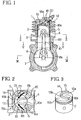
- the engine has an inlet port 3 to suction the air-fuel mixture into a cylinder 1 and an exhaust port 4 to exhaust combustion gas.
- the mixture guided into the cylinder 1 from the inlet port 3 is charged into a crank chamber 6 and compressed therein by lowering of the piston 2.
- a crank case 7 having the crank chamber 6 inside is provided with a passage 8a extending upward from the bottom of the crank chamber 6 through the wall on one side of the crank case 7.
- the cylinder 1 has passages 8b extending vertically upward from the position connecting with said passage 8a of the crank case 7 through the side wall on both sides of the cylinder 1.
- the upper ends of these passages 8a and 8b connect with scavenging charge ports 5 opened on the wall on both sides of the cylinder 1.
- the passage 8a provided inside the side wall of the crank case 7 is formed by a symmetric pair of concave grooves 9 extending upward from the bottom of the crank chamber 6 on the contacting surface of the symmetric pair of case members 7a, 7b which constitute the crank case 7.
- the passages 8b provided inside the wall on both sides of the cylinder 1 are positioned above a pair of right and left concave grooves 10 provided horizontally and branching into the largest curve possible on both sides of the cylinder 1 connecting with the passage 8a on the side of the crank case 7.
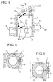
- the passages 8b extend vertically upward through the wall on both sides of the cylinder 1 with a hole having an elongated section as shown in Fig. 2 from the said horizontal concave grooves 10.
- the tips of the passages 8b connect with the scavenging charge ports 5 opened on the wall on both sides of the cylinder 1. As shown in Fig. 2, these ports 5 are connected via the passages 13 inclined toward the inner wall 12 opposite the exhaust port 4 inside the cylinder 1.
- a deflector 14 at the top surface of the piston 2 in the cylinder 1 to direct the air-fuel mixture flow introduced from the scavenging charge ports 5 toward the inner wall 12 opposite the exhaust port 4 in the cylinder 1.
- the deflector 14 comprises a embossed part shaped like the letter U when viewed from above, projecting on the top surface of the piston 2.
- the opening 15a of the U-shaped boss 15 is positioned such that it is on the side of the exhaust port 4 of the cylinder 1. It is preferable that the middle portion of the U-shaped boss 15 of the deflector 14 has a smoothly curved line 15b, and other portion of the boss 15 has somewhat slant lines as in the letter V.
- the top surface of the piston 2 is sectioned by the U-shaped boss 15 of the deflector 14 into the inside area 16a and the outside area 16b.
- the boss 15 constituting the U-shaped deflector 14 has a square or rectangular cross section so that the inner and outer sides thereof form substantially vertical walls in respect of the top surface of the piston 2. As shown in Fig. 4, the height 15h of the convex wall 15 should preferably be about one half of the longitudinal length 4h of the exhaust port 4.
- the outer side of the boss 15 forming the letter U are positioned inside the passage of the air-fuel mixture 21 to be introduced from the scavenging charge ports 5 as shown by the arrows in Fig. 2, and guide the mixture 21 toward the inner wall 12 opposite the exhaust port 4 in the cylinder 1 while flowing over the outside area 16b along the respective side of the boss 15.
- the cylinder head 17 opposite the top surface of the piston 2 provided with the deflector 14 is provided with a dome-shaped combustion chamber 18 designed to be fit into the inside area 16a surrounded by the deflector 14 and the boss 15 of the deflector 14.
- the inner periphery of the combustion chamber 18 fits the configurations of the outer side and the top surface of the deflector 14 so that when the piston 2 rises and reaches the top dead center, the deflector 14 and its inside area 16a are fitted inside and form a space for compressing the air-fuel mixture 21.
- the combustion chamber 18 is positioned in such a way that the axial direction of an ignition plug 20 is inclined toward the direction facing the flow of the mixture 21 which flows from the direction of the inner wall 12 opposite the exhaust port 4 in the cylinder 1, and the ceiling 18a, which corresponds to the center of the inside area 16a surrounded by the deflector 14, of the combustion chamber 18 is shaped so that the air-fuel mixture 21 flowing from the direction of the inner wall 12 in the cylinder 1 may be guided easily toward the ignition plug 20.
- ceiling 19 which corresponds to the outside area 16b on the top surface of the piston 2.
- the air-fuel mixture is suctioned into the crank chamber 6 from the suction port 3 by the rising of the piston 2, is compressed inside the crank chamber 6 by the lowering of the piston 2, passes the scavenging passages 8b provided in the cylinder 1 from the scavenging passage 8a provided in the crank case 7, and charged into the cylinder 1 from the scavenging charge ports 5.
- the passage 8a provided inside the wall of the crank case 7 connects with the passages 8b provided in the wall on both sides of the cylinder 1 above, and the air-fuel mixture 21 blown up from the lower passage 8a is charged into the horizontal concave grooves 10 on the contact surface of the crank case 7 and the cylinder 1.
- the mixture 21a of larger mass containing lots of fuel particles is pushed toward the wall on the left side of the concave groove 10 and crash into the wall.
- the mixture 21a of larger mass and containing more fuel particles which crashed into the wall on the left end of the concave groove 10 rises along the left side of the passage 8b and is blown toward the inside wall 12 from a position far from the exhaust port 4 of the scavenging charge ports 5 shown in Fig. 2.
- the air-fuel mixture 21b with smaller mass and less fuel particles flows toward the direction of the upper scavenging charge ports 5 by passing through the passage 8b from the right hand side of the concave groove 10 shown in Fig. 7.
- Outside the scavenging charge ports 5 is the boss 15 of the deflector 14 which stops the mixture from riding over the boss 15 and flowing toward the inside area 16a, thus preventing leakage from the exhaust port 4.
- Passing the air-fuel mixture 21 through the passages 8a, 8b provided in the walls of the crank case 7 and the cylinder 1 and heating or vibrating the mixture mean promoting atomization and evaporation of the liquid fuel and creating air-fuel mixture of a higher density containing a greater amount of fuel particles. This in turn enhances the combustion efficiency and decreases the liquid stage fuel which causes high HC emission.
- Giving a curved shape to the concave grooves 10 provided horizontally on the contact surface of the top edge of the crank case 7 and the lower edge of the cylinder 1 or bending the connecting part of the concave grooves 10 and the passage 8b decrease the resistance toward the air-fuel mixture 21 passing through the passage and prevent lowering of the output.
- the air-fuel mixture 21 introduced into the cylinder 1 from the scavenging charge ports 5 crashes into the wall of the deflector 14 and is prevented from flowing toward the inside area 16a, most of the mixture is guided toward the inside wall 12 opposite the exhaust port 4 after passing over the outside area 16b and flows toward the cylinder head 17. Therefore, there is formed only the layer of the air-fuel mixture 21 of the cylinder 1 flowing in loops along the inner wall of the cylinder, but the flow toward the center of the cylinder does not occur. This remarkably restrains the amount of liquid stage gas leaking from the exhaust port before combustion.
Landscapes
- Engineering & Computer Science (AREA)
- Chemical & Material Sciences (AREA)
- Combustion & Propulsion (AREA)
- Mechanical Engineering (AREA)
- General Engineering & Computer Science (AREA)
- Combustion Methods Of Internal-Combustion Engines (AREA)
- Cylinder Crankcases Of Internal Combustion Engines (AREA)
Applications Claiming Priority (3)
| Application Number | Priority Date | Filing Date | Title |
|---|---|---|---|
| JP25140497 | 1997-09-02 | ||
| JP9251404A JPH1182027A (ja) | 1997-09-02 | 1997-09-02 | 2サイクルエンジン |
| JP251404/97 | 1997-09-02 |
Publications (2)
| Publication Number | Publication Date |
|---|---|
| EP0900925A1 true EP0900925A1 (fr) | 1999-03-10 |
| EP0900925B1 EP0900925B1 (fr) | 2000-03-22 |
Family
ID=17222347
Family Applications (1)
| Application Number | Title | Priority Date | Filing Date |
|---|---|---|---|
| EP98116455A Expired - Lifetime EP0900925B1 (fr) | 1997-09-02 | 1998-08-31 | Moteur à deux temps |
Country Status (4)
| Country | Link |
|---|---|
| US (1) | US5911202A (fr) |
| EP (1) | EP0900925B1 (fr) |
| JP (1) | JPH1182027A (fr) |
| DE (1) | DE69800098T2 (fr) |
Citations (4)
| Publication number | Priority date | Publication date | Assignee | Title |
|---|---|---|---|---|
| US3858562A (en) * | 1972-11-17 | 1975-01-07 | Brunswick Corp | Multiple input port internal combustion engine |
| US4146004A (en) * | 1976-08-30 | 1979-03-27 | Outboard Marine Corporation | Internal combustion engine including spark plug anti-fouling means |
| JPS5928628A (ja) | 1982-08-09 | 1984-02-15 | Sumitomo Electric Ind Ltd | 光による温度センサ |
| DE19715482A1 (de) * | 1996-04-16 | 1997-11-06 | Kioritz Corp | Zweitaktverbrennungsmotor |
-
1997
- 1997-09-02 JP JP9251404A patent/JPH1182027A/ja active Pending
-
1998
- 1998-04-14 US US09/059,758 patent/US5911202A/en not_active Expired - Lifetime
- 1998-08-31 EP EP98116455A patent/EP0900925B1/fr not_active Expired - Lifetime
- 1998-08-31 DE DE69800098T patent/DE69800098T2/de not_active Expired - Lifetime
Patent Citations (4)
| Publication number | Priority date | Publication date | Assignee | Title |
|---|---|---|---|---|
| US3858562A (en) * | 1972-11-17 | 1975-01-07 | Brunswick Corp | Multiple input port internal combustion engine |
| US4146004A (en) * | 1976-08-30 | 1979-03-27 | Outboard Marine Corporation | Internal combustion engine including spark plug anti-fouling means |
| JPS5928628A (ja) | 1982-08-09 | 1984-02-15 | Sumitomo Electric Ind Ltd | 光による温度センサ |
| DE19715482A1 (de) * | 1996-04-16 | 1997-11-06 | Kioritz Corp | Zweitaktverbrennungsmotor |
Also Published As
| Publication number | Publication date |
|---|---|
| US5911202A (en) | 1999-06-15 |
| DE69800098T2 (de) | 2000-10-05 |
| JPH1182027A (ja) | 1999-03-26 |
| EP0900925B1 (fr) | 2000-03-22 |
| DE69800098D1 (de) | 2000-04-27 |
Similar Documents
| Publication | Publication Date | Title |
|---|---|---|
| US5020485A (en) | Two-cycle engine | |
| US4359027A (en) | Two-cycle internal combustion engine having high swirl combustion chamber | |
| JPS6212370B2 (fr) | ||
| US7243622B2 (en) | Two-stroke internal combustion engine | |
| US5901673A (en) | Two-cycle internal combustion engine | |
| US6279521B1 (en) | Two-cycle engine | |
| JPH11107761A (ja) | 層状掃気2サイクルエンジン | |
| JP3404288B2 (ja) | 2サイクルエンジン | |
| EP0900925B1 (fr) | Moteur à deux temps | |
| US5372105A (en) | Combustion chamber for two-cycle internal combustion engine | |
| JP3626361B2 (ja) | 2サイクルエンジン | |
| JPH04224231A (ja) | 筒内噴射式内燃機関 | |
| US20040065281A1 (en) | Two-stroke engine transfer ports | |
| JPH06212974A (ja) | 2ストロークサイクルエンジン | |
| JPS5855327B2 (ja) | 副燃焼室付内燃機関の燃焼室 | |
| JP2002089270A (ja) | 2サイクル内燃機関 | |
| AU710491B2 (en) | Crank chamber precompression spark ignition two-stroke internal combustion engine | |
| JPH1113474A (ja) | 直接噴射式ディーゼルエンジンの燃焼室 | |
| JP4301631B2 (ja) | 層状掃気2サイクルエンジン | |
| JPS5934417A (ja) | 2サイクルエンジン | |
| US4244329A (en) | Clean spark ignition internal combustion engine | |
| JP2936798B2 (ja) | 筒内噴射式内燃機関 | |
| JP2000186560A (ja) | 層状掃気2サイクルエンジン | |
| JPH0426657Y2 (fr) | ||
| JPS6032008B2 (ja) | クランク室予圧式2サイクルエンジンの掃気装置 |
Legal Events
| Date | Code | Title | Description |
|---|---|---|---|
| PUAI | Public reference made under article 153(3) epc to a published international application that has entered the european phase |
Free format text: ORIGINAL CODE: 0009012 |
|
| AK | Designated contracting states |
Kind code of ref document: A1 Designated state(s): DE GB IT SE |
|
| AX | Request for extension of the european patent |
Free format text: AL;LT;LV;MK;RO;SI |
|
| 17P | Request for examination filed |
Effective date: 19990413 |
|
| GRAG | Despatch of communication of intention to grant |
Free format text: ORIGINAL CODE: EPIDOS AGRA |
|
| 17Q | First examination report despatched |
Effective date: 19990805 |
|
| GRAG | Despatch of communication of intention to grant |
Free format text: ORIGINAL CODE: EPIDOS AGRA |
|
| GRAH | Despatch of communication of intention to grant a patent |
Free format text: ORIGINAL CODE: EPIDOS IGRA |
|
| GRAG | Despatch of communication of intention to grant |
Free format text: ORIGINAL CODE: EPIDOS AGRA |
|
| GRAH | Despatch of communication of intention to grant a patent |
Free format text: ORIGINAL CODE: EPIDOS IGRA |
|
| AKX | Designation fees paid |
Free format text: DE GB IT SE |
|
| GRAA | (expected) grant |
Free format text: ORIGINAL CODE: 0009210 |
|
| AK | Designated contracting states |
Kind code of ref document: B1 Designated state(s): DE GB IT SE |
|
| REF | Corresponds to: |
Ref document number: 69800098 Country of ref document: DE Date of ref document: 20000427 |
|
| ITF | It: translation for a ep patent filed | ||
| EN | Fr: translation not filed | ||
| PLBE | No opposition filed within time limit |
Free format text: ORIGINAL CODE: 0009261 |
|
| STAA | Information on the status of an ep patent application or granted ep patent |
Free format text: STATUS: NO OPPOSITION FILED WITHIN TIME LIMIT |
|
| 26N | No opposition filed | ||
| REG | Reference to a national code |
Ref country code: GB Ref legal event code: IF02 |
|
| REG | Reference to a national code |
Ref country code: GB Ref legal event code: 732E Free format text: REGISTERED BETWEEN 20090219 AND 20090225 |
|
| REG | Reference to a national code |
Ref country code: GB Ref legal event code: 732E Free format text: REGISTERED BETWEEN 20150129 AND 20150204 |
|
| REG | Reference to a national code |
Ref country code: DE Ref legal event code: R082 Ref document number: 69800098 Country of ref document: DE Representative=s name: PRUEFER & PARTNER GBR, DE |
|
| REG | Reference to a national code |
Ref country code: DE Ref legal event code: R082 Ref document number: 69800098 Country of ref document: DE Representative=s name: PRUEFER & PARTNER MBB PATENTANWAELTE RECHTSANW, DE Effective date: 20150309 Ref country code: DE Ref legal event code: R082 Ref document number: 69800098 Country of ref document: DE Representative=s name: PRUEFER & PARTNER GBR, DE Effective date: 20150309 Ref country code: DE Ref legal event code: R081 Ref document number: 69800098 Country of ref document: DE Owner name: HITACHI KOKI CO., LTD., JP Free format text: FORMER OWNER: NIKKO TANAKA ENGINEERING CO.,LTD., NARASHINO, CHIBA, JP Effective date: 20150309 |
|
| PGFP | Annual fee paid to national office [announced via postgrant information from national office to epo] |
Ref country code: DE Payment date: 20150825 Year of fee payment: 18 Ref country code: GB Payment date: 20150826 Year of fee payment: 18 |
|
| PGFP | Annual fee paid to national office [announced via postgrant information from national office to epo] |
Ref country code: SE Payment date: 20150811 Year of fee payment: 18 |
|
| PGFP | Annual fee paid to national office [announced via postgrant information from national office to epo] |
Ref country code: IT Payment date: 20150827 Year of fee payment: 18 |
|
| REG | Reference to a national code |
Ref country code: DE Ref legal event code: R119 Ref document number: 69800098 Country of ref document: DE |
|
| GBPC | Gb: european patent ceased through non-payment of renewal fee |
Effective date: 20160831 |
|
| PG25 | Lapsed in a contracting state [announced via postgrant information from national office to epo] |
Ref country code: SE Free format text: LAPSE BECAUSE OF NON-PAYMENT OF DUE FEES Effective date: 20160901 |
|
| REG | Reference to a national code |
Ref country code: SE Ref legal event code: EUG |
|
| PG25 | Lapsed in a contracting state [announced via postgrant information from national office to epo] |
Ref country code: GB Free format text: LAPSE BECAUSE OF NON-PAYMENT OF DUE FEES Effective date: 20160831 Ref country code: DE Free format text: LAPSE BECAUSE OF NON-PAYMENT OF DUE FEES Effective date: 20170301 |
|
| PG25 | Lapsed in a contracting state [announced via postgrant information from national office to epo] |
Ref country code: IT Free format text: LAPSE BECAUSE OF NON-PAYMENT OF DUE FEES Effective date: 20160831 |