EP0900952A2 - Transmission à courroie - Google Patents
Transmission à courroie Download PDFInfo
- Publication number
- EP0900952A2 EP0900952A2 EP98115864A EP98115864A EP0900952A2 EP 0900952 A2 EP0900952 A2 EP 0900952A2 EP 98115864 A EP98115864 A EP 98115864A EP 98115864 A EP98115864 A EP 98115864A EP 0900952 A2 EP0900952 A2 EP 0900952A2
- Authority
- EP
- European Patent Office
- Prior art keywords
- toothed
- belt
- tooth
- ribs
- belt drive
- Prior art date
- Legal status (The legal status is an assumption and is not a legal conclusion. Google has not performed a legal analysis and makes no representation as to the accuracy of the status listed.)
- Granted
Links
- 238000004519 manufacturing process Methods 0.000 description 12
- 238000003801 milling Methods 0.000 description 11
- 230000000694 effects Effects 0.000 description 8
- 239000011295 pitch Substances 0.000 description 8
- 230000008901 benefit Effects 0.000 description 6
- 210000001331 nose Anatomy 0.000 description 6
- 238000004804 winding Methods 0.000 description 6
- 238000011161 development Methods 0.000 description 5
- 230000018109 developmental process Effects 0.000 description 5
- 239000000463 material Substances 0.000 description 3
- 238000013016 damping Methods 0.000 description 2
- 230000003292 diminished effect Effects 0.000 description 2
- 238000005516 engineering process Methods 0.000 description 2
- 238000000034 method Methods 0.000 description 2
- 238000007514 turning Methods 0.000 description 2
- 230000009471 action Effects 0.000 description 1
- 230000000295 complement effect Effects 0.000 description 1
- 238000010276 construction Methods 0.000 description 1
- 230000003247 decreasing effect Effects 0.000 description 1
- 238000013461 design Methods 0.000 description 1
- 230000012447 hatching Effects 0.000 description 1
- 238000011835 investigation Methods 0.000 description 1
- 230000002427 irreversible effect Effects 0.000 description 1
- 238000003754 machining Methods 0.000 description 1
- 230000004048 modification Effects 0.000 description 1
- 238000012986 modification Methods 0.000 description 1
- 230000008569 process Effects 0.000 description 1
- 230000002441 reversible effect Effects 0.000 description 1
- 238000007493 shaping process Methods 0.000 description 1
- 229920001169 thermoplastic Polymers 0.000 description 1
- 230000007704 transition Effects 0.000 description 1
Images





Classifications
-
- F—MECHANICAL ENGINEERING; LIGHTING; HEATING; WEAPONS; BLASTING
- F16—ENGINEERING ELEMENTS AND UNITS; GENERAL MEASURES FOR PRODUCING AND MAINTAINING EFFECTIVE FUNCTIONING OF MACHINES OR INSTALLATIONS; THERMAL INSULATION IN GENERAL
- F16H—GEARING
- F16H7/00—Gearings for conveying rotary motion by endless flexible members
- F16H7/02—Gearings for conveying rotary motion by endless flexible members with belts; with V-belts
- F16H7/023—Gearings for conveying rotary motion by endless flexible members with belts; with V-belts with belts having a toothed contact surface or regularly spaced bosses or hollows for slipless or nearly slipless meshing with complementary profiled contact surface of a pulley
Definitions
- the invention relates to a belt drive with a toothed belt and a tooth lock washer, one of interlocking Toothed ribs and tooth grooves have teeth formed.
- the operating behavior of such belt drives is, inter alia, determined by two essential parameters, namely on the one hand from the side guide of the toothed belt and to the other from the development of running noises.
- the invention has for its object in manufacturing technology simple way of operating the To improve belt drive.
- the belt drive mentioned at the beginning is used to solve this problem characterized in that the Interlocking at least on a section of the extension the toothed ribs and the tooth grooves in an arc over the toothed belt and the toothed disk runs.
- the timing belt runs extremely low vibration, so that on toothed tensioners, as they otherwise for vibration damping were required can be waived.
- the belt drive according to the invention enables compared conventional gears are at least 5% higher Tooth load under otherwise identical conditions, namely due to the fact that the length of the toothed ribs is greater is than the width of the timing belt. The length of the engagement is thus increased so that the increased tooth load the permissible Flank pressure does not exceed.
- the invention basically leaves any arch shape to. For manufacturing reasons, however, it is particularly advantageous, the arcuate sections of the toothed ribs and the tooth grooves to form a circular arc.
- the invention is not a limitation on what the Tooth division concerns.
- it is particularly advantageous that the course of the toothing is designed such that a front lying in the running direction Toothed rib only stops its engaging movement when the next following toothed rib with its engaging movement has already started. This promotes smooth running of the belt drive.
- the curved toothing form elliptically, with the long axis of the ellipse in Direction of rotation of the toothed belt or the pulley has.
- a preferred feature is that to the arcuate sections of the tooth ribs and the tooth grooves a straight section connects on both sides. So there is a toothing, the straight line Legs are connected by an arch. Between the individual toothed rib sections can well Gaps should be provided.
- the teeth in at least two in the direction of rotation to divide running rows.
- Each row is with toothed ribs and tooth grooves, with a wide variety of shapes possible are. So the tooth ribs and the Merge tooth grooves of adjacent rows directly into one another. Also adjacent rows can be between the toothed ribs Gaps are provided that allow the air to escape during facilitate the intervention process.
- Very advantageous is the tooth ribs and the tooth grooves in one of the Rows of teeth in the direction of rotation against those in the neighboring To move row. This also makes it easier Escape the air and also helps keep the running smooth to increase the belt drive.
- the tooth ribs and the tooth grooves preferably form in adjacent rows of the teeth offset against each other Half arches. This results in a particularly simple one Template.
- a major advantage is also achieved by that the arch vertex of the gearing in the running direction of the toothed belt or toothed pulley are directed. It it was found that this results in a particularly reliable lateral guidance of the timing belt results. It actually results a self-centering effect that the timing belt automatically returns to the correct engagement position, provided external intervention temporarily centering should have disturbed.
- the invention is further developed suggested that the tooth ribs and the tooth grooves in adjacent rows of teeth in opposite directions to each other form directed arches.
- the effect of self-centering is also the result of a reversing running direction of the Belt drive.
- the toothed ribs of the toothed belt and the tooth grooves the toothed disc each have a constant width, while the toothed grooves of the toothed belt and the toothed ribs taper the lock washer towards the ends.
- the advantage achieved is in the field of manufacturing technology.
- the toothed lock washer is profiled Milling cutter worked, which is guided in an arc and while doing so milled a tooth groove. For the next tooth groove this will be System switched by one tooth pitch.
- the tooth ribs are thus on their convex surface from the inside of the Milling cutter in its first position, while the concave Flanks of exposure to the outside of the router in subject to its second position.
- the essential simplification is that the swivel path of the cutter - at circular toothing the swivel radius of the milling cutter - remains constant. Same conditions, but mirror images, are in the manufacture of toothed washer-like Form given for the timing belt.
- each tooth groove of the toothed belt runs a channel of constant width. Their depth is limited by the longitudinal wire strands, which are embedded in the material of the timing belt.
- the advantage lies in the manufacturing area.
- the shape for creating the timing belt is, as mentioned, designed as a toothed washer. Be over this tooth lock washer the wire strands taut. To avoid the wire strands form the bottoms of the tooth grooves of the finished toothed belt, each toothed rib of the shape bears a so-called wrap nose very narrow width. If you use the wrap lugs together the tooth grooves of the form, so the winding noses, just like the toothed ribs of the form, one towards the edges received decreasing width. This is prohibited due to the anyway extremely narrow width of the winding lugs.
- the Swivel radius of the milling cutter (it is a separate one such) changed so that the width of the Winding noses remains constant.
- This gives the constant Width of the grooves in the tooth grooves of the toothed belt.
- the geometrical Relationships, namely the tooth pitch, the arch shape the teeth and their width are chosen so that not only, as mentioned, a wrap nose more constant Width results, but also that the toothed ribs of the form (i.e. the tooth grooves of the toothed belt) at the ends a minimum width do not fall below. This is determined by the foot width of the wrap nose.
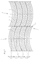
- FIG. 1 shows in FIG. 1 up to 8 top views of the profiled side of different Timing belt, the contour of the Toothed belt is indicated.
- FIG. 9 are some between the toothed ribs of the toothed belt Toothed ribs of the toothed disk indicated.
- the toothed ribs 2 and the tooth grooves 3 run in an arc shape across the width of the timing belt 1, symmetrically to its longitudinal center line 4.
- the toothing is in the present Case formed in a circular arc.
- each arc from the longitudinal center line 4 to the edges of the toothed belt, plus the toothed rib thickness, is greater than one tooth pitch y. This ensures that a toothed rib lying at the front in the running direction their interventional movement ends only when the next succeeding Toothed rib already started to move Has.
- the toothed belt 1 is in the present case for one non-reversible operation provided for one Direction of travel from bottom to top in Fig. 1.
- the apex of the Arches point in the direction of travel.
- the toothed belt 1 forms together with an associated one Toothed pulley a belt drive according to the invention.
- the tooth lock washer is complementary to their tooth ribs and tooth grooves educated. A separate presentation was therefore made waived.
- the belt drive ensures that the Timing belt on the pulley, there is no risk that the timing belt immediately with lateral deflection runs up on the toothed ribs of the toothed disc. Rather causes the automatic toothing in the running direction is automatic Re-centering of a deflected toothed belt.
- the Belt drive works with maximum smoothness and minimal Noise development because there is no polygon effect. Toothed Tension rollers for vibration damping are not required. Also cylindrical support rollers without "rattling" are tangentially overrun. The same applies to the wrapping cylindrical pulleys.
- the toothed ribs 2nd are of constant width, while the tooth grooves 3 of taper from the center towards the edges. This is on attributed a particularly simple way of manufacturing.
- the toothed pulley-like tool for shaping the toothed belt is made by making its tooth grooves later form the toothed ribs of the toothed belt from a milling cutter be milled, the pivot point of each one tooth pitch is advanced.
- the toothed ribs of the tool, the later form the tooth grooves of the toothed belt so are on the convex flank from the inside of the milling cutter milled first position, while the concave flanks of the Action of the outside of the milling cutter in its second position subject to.
- the crucial simplification is there in that the turning radius of the milling cutter is not changed got to. This advantage particularly affects the Manufacture of the actual tooth lock washer.
- each tooth groove 3 has a channel 5 of constant width, which extends up to extends to wire strands 6, which in the material of the toothed belt 1 are embedded.
- the channel 5 is produced by the so-called winding nose on the toothed ribs of the tool, over which the wire strands 6 are tensioned.
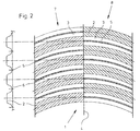
- toothed disc 3 is the toothing in the two rows 7 and 8 divided. However, the tooth ribs close here and the tooth grooves of the two rows directly against each other. Nevertheless, the toothed disc can be made in this embodiment be made in one piece.
- the milling cutter runs through a toothed disk on its circumferential center line a turning point. This is shown in Fig. 3 on the lower arcuate transitions of the toothed ribs 2 on the Longitudinal center line 4 of the toothed belt 1.
- Tips provided the toothed lock washer consists of two separate, together connected discs is manufactured.
- FIG. 4 A corresponding embodiment is shown in FIG. 4. Otherwise, this embodiment differs 3 in that the toothed ribs 2 and Tooth grooves 3 in the two rows 7 and 8 each from half arches consist.
- toothed ribs 2 and toothed grooves 3 of the two rows 7 and 8 are offset from each other.
- the belt drives described so far are preferred for irreversible direction of rotation provided, the apex of the Point the arches of the toothing in the direction of travel.
- the embodiment 6, however, is designed so that the Belt drive the advantage of self-centering in both Running directions developed.
- the toothed ribs 2 and the tooth grooves 3 of the two rows 7 and 8 in opposite directions arches facing each other.
- FIG. 8 essentially corresponds 1, but with the proviso that only the middle section of the toothing, namely the area formed arcuate on both sides of the longitudinal center line 4 is. Straight sections are connected to the sides of the arches on.
Landscapes
- Engineering & Computer Science (AREA)
- General Engineering & Computer Science (AREA)
- Mechanical Engineering (AREA)
- Devices For Conveying Motion By Means Of Endless Flexible Members (AREA)
- Pulleys (AREA)
- Structure Of Belt Conveyors (AREA)
- Belt Conveyors (AREA)
- Transmission Devices (AREA)
- Transmissions By Endless Flexible Members (AREA)
Applications Claiming Priority (4)
| Application Number | Priority Date | Filing Date | Title |
|---|---|---|---|
| DE29723242U | 1997-09-08 | ||
| DE29723242 | 1997-09-08 | ||
| DE19810596 | 1998-03-11 | ||
| DE19810596A DE19810596A1 (de) | 1997-09-08 | 1998-03-11 | Riementrieb |
Publications (3)
| Publication Number | Publication Date |
|---|---|
| EP0900952A2 true EP0900952A2 (fr) | 1999-03-10 |
| EP0900952A3 EP0900952A3 (fr) | 2001-01-31 |
| EP0900952B1 EP0900952B1 (fr) | 2002-06-19 |
Family
ID=26044559
Family Applications (1)
| Application Number | Title | Priority Date | Filing Date |
|---|---|---|---|
| EP98115864A Expired - Lifetime EP0900952B1 (fr) | 1997-09-08 | 1998-08-22 | Transmission à courroie |
Country Status (6)
| Country | Link |
|---|---|
| US (1) | US6142901A (fr) |
| EP (1) | EP0900952B1 (fr) |
| JP (1) | JP3040380B2 (fr) |
| AT (1) | ATE219559T1 (fr) |
| CA (1) | CA2246823C (fr) |
| ES (1) | ES2179406T3 (fr) |
Families Citing this family (6)
| Publication number | Priority date | Publication date | Assignee | Title |
|---|---|---|---|---|
| DE19958709C2 (de) * | 1999-12-06 | 2001-10-25 | Kone Corp | Verfahren und Einrichtung zur Reduzierung des Polygoneffektes im Umlenkbereich von Personenförderanlagen |
| WO2002088015A1 (fr) * | 2001-04-27 | 2002-11-07 | Kone Corporation | Procede et dispositif pour reduire l'effet polygone dans la zone de renvoi de systemes de transport de passagers |
| DE10206510B4 (de) * | 2002-02-16 | 2004-02-12 | Breco Antriebstechnik Breher Gmbh & Co. | Verfahren und Vorrichtung zum Herstellen eines Zahnriemens |
| US20050113199A1 (en) * | 2003-11-26 | 2005-05-26 | Brecoflex Co., L.L.C. | Toothed belt with tooth reinforcements |
| GB2587297B (en) | 2015-03-31 | 2021-08-04 | Fisher & Paykel Healthcare Ltd | A user interface and system for supplying gases to an airway |
| KR20240157114A (ko) | 2016-08-11 | 2024-10-31 | 피셔 앤 페이켈 핼스케어 리미티드 | 압궤 가능 도관, 환자 인터페이스 및 헤드기어 연결부 |
Family Cites Families (9)
| Publication number | Priority date | Publication date | Assignee | Title |
|---|---|---|---|---|
| DE248852C (fr) * | 1911-04-28 | 1912-07-04 | ||
| US2718790A (en) * | 1954-09-29 | 1955-09-27 | Eastman Kodak Co | Power transmission mechanism |
| US3216273A (en) * | 1963-05-08 | 1965-11-09 | Jr Henry G Colmer | Power transmitting means |
| DE2910871C2 (de) * | 1979-03-20 | 1982-04-22 | Bayerische Motoren Werke AG, 8000 München | Zahnriementrieb |
| US4647278A (en) * | 1986-02-11 | 1987-03-03 | Dayco Corporation | Endless power transmission belt construction and method of making the same |
| SU1762052A1 (ru) * | 1990-02-26 | 1992-09-15 | А.И.Турменко | Ременна зубчата передача |
| FR2679616A1 (fr) * | 1991-07-25 | 1993-01-29 | Caoutchouc Manuf Plastique | Perfectionnement aux ensembles de transmission synchrone pour delocaliser les contraintes dans la courroie. |
| FR2686959A1 (fr) * | 1992-02-03 | 1993-08-06 | Caoutchouc Manuf Plastique | Ensemble de transmission a denture oblique. |
| US5704861A (en) * | 1996-08-28 | 1998-01-06 | The Goodyear Tire & Rubber Company | Synchronous drive belt/pulley combination |
-
1998
- 1998-08-22 ES ES98115864T patent/ES2179406T3/es not_active Expired - Lifetime
- 1998-08-22 EP EP98115864A patent/EP0900952B1/fr not_active Expired - Lifetime
- 1998-08-22 AT AT98115864T patent/ATE219559T1/de active
- 1998-09-02 US US09/145,109 patent/US6142901A/en not_active Expired - Lifetime
- 1998-09-04 CA CA002246823A patent/CA2246823C/fr not_active Expired - Lifetime
- 1998-09-07 JP JP10252063A patent/JP3040380B2/ja not_active Expired - Lifetime
Non-Patent Citations (1)
| Title |
|---|
| None |
Also Published As
| Publication number | Publication date |
|---|---|
| US6142901A (en) | 2000-11-07 |
| EP0900952B1 (fr) | 2002-06-19 |
| JP3040380B2 (ja) | 2000-05-15 |
| EP0900952A3 (fr) | 2001-01-31 |
| CA2246823A1 (fr) | 1999-03-08 |
| CA2246823C (fr) | 2003-02-04 |
| ES2179406T3 (es) | 2003-01-16 |
| ATE219559T1 (de) | 2002-07-15 |
| JPH11173389A (ja) | 1999-06-29 |
Similar Documents
| Publication | Publication Date | Title |
|---|---|---|
| DE2126858C2 (de) | Riementrieb | |
| EP0925093B1 (fr) | Systeme de tapis roulant | |
| EP0601279B1 (fr) | Courroie crantée et courroie trapézoidale pour tapis roulant | |
| CH636419A5 (de) | Mechanische kraftuebertragungseinrichtung. | |
| DE602004013223T2 (de) | Zahnrad für eine Kette | |
| DE2141205A1 (de) | Lenkgetriebe veränderlicher Übersetzung | |
| DE60304503T2 (de) | Zahnprofil eines Zahnrads | |
| DE10147407B4 (de) | Zahnketten-Kraftübertragungs-Vorrichtung | |
| DE3121662C2 (de) | Getriebe, insbesondere Planetengetriebe | |
| DE4316913C2 (de) | Breitschlitzdüse | |
| DE2738426A1 (de) | Gezahnter endlosriemen | |
| EP0900952B1 (fr) | Transmission à courroie | |
| DE10157020A1 (de) | Riemenscheibeneinheit | |
| WO1986007101A1 (fr) | Transmission a courroie tangentielle | |
| DE2805469A1 (de) | Drehwalze fuer jalousienleiterband | |
| DE3520751A1 (de) | Riemenscheibe fuer bewegungsuebertragung mit einem biegsamen zahnriemen | |
| EP0363939B1 (fr) | Transmission de conversion d'un mouvement rectiligne en un mouvement rotatif et inversement | |
| DE2950258A1 (de) | Verdichtungs- oder entspannungsmaschine | |
| DE2061101B2 (de) | Kugelschraubtrieb | |
| DE19810596A1 (de) | Riementrieb | |
| DE68907554T2 (de) | Triebkette für stufenlos regelbares Kegelscheibengetriebe. | |
| DE3414744A1 (de) | Riemen zum uebertragen von bewegung zwischen zwei riemenscheiben | |
| DE20214565U1 (de) | Elektromotorischer Möbelantrieb | |
| DE69912357T2 (de) | Rolle zum Führen und/oder Spannen eines Treibriemens | |
| DE29724295U1 (de) | Rollenkettenrad |
Legal Events
| Date | Code | Title | Description |
|---|---|---|---|
| PUAI | Public reference made under article 153(3) epc to a published international application that has entered the european phase |
Free format text: ORIGINAL CODE: 0009012 |
|
| AK | Designated contracting states |
Kind code of ref document: A2 Designated state(s): AT BE CH DE ES FR GB IT LI NL |
|
| AX | Request for extension of the european patent |
Free format text: AL;LT;LV;MK;RO;SI |
|
| PUAL | Search report despatched |
Free format text: ORIGINAL CODE: 0009013 |
|
| AK | Designated contracting states |
Kind code of ref document: A3 Designated state(s): AT BE CH CY DE DK ES FI FR GB GR IE IT LI LU MC NL PT SE |
|
| AX | Request for extension of the european patent |
Free format text: AL;LT;LV;MK;RO;SI |
|
| 17P | Request for examination filed |
Effective date: 20010216 |
|
| 17Q | First examination report despatched |
Effective date: 20010320 |
|
| AKX | Designation fees paid |
Free format text: AT BE CH DE ES FR GB IT LI NL |
|
| GRAG | Despatch of communication of intention to grant |
Free format text: ORIGINAL CODE: EPIDOS AGRA |
|
| GRAG | Despatch of communication of intention to grant |
Free format text: ORIGINAL CODE: EPIDOS AGRA |
|
| GRAH | Despatch of communication of intention to grant a patent |
Free format text: ORIGINAL CODE: EPIDOS IGRA |
|
| GRAH | Despatch of communication of intention to grant a patent |
Free format text: ORIGINAL CODE: EPIDOS IGRA |
|
| GRAA | (expected) grant |
Free format text: ORIGINAL CODE: 0009210 |
|
| AK | Designated contracting states |
Kind code of ref document: B1 Designated state(s): AT BE CH DE ES FR GB IT LI NL |
|
| REF | Corresponds to: |
Ref document number: 219559 Country of ref document: AT Date of ref document: 20020715 Kind code of ref document: T |
|
| REG | Reference to a national code |
Ref country code: GB Ref legal event code: FG4D Free format text: NOT ENGLISH |
|
| REG | Reference to a national code |
Ref country code: CH Ref legal event code: EP |
|
| GBT | Gb: translation of ep patent filed (gb section 77(6)(a)/1977) |
Effective date: 20020619 |
|
| REF | Corresponds to: |
Ref document number: 59804487 Country of ref document: DE Date of ref document: 20020725 |
|
| ET | Fr: translation filed | ||
| REG | Reference to a national code |
Ref country code: ES Ref legal event code: FG2A Ref document number: 2179406 Country of ref document: ES Kind code of ref document: T3 |
|
| PLBE | No opposition filed within time limit |
Free format text: ORIGINAL CODE: 0009261 |
|
| STAA | Information on the status of an ep patent application or granted ep patent |
Free format text: STATUS: NO OPPOSITION FILED WITHIN TIME LIMIT |
|
| 26N | No opposition filed |
Effective date: 20030320 |
|
| REG | Reference to a national code |
Ref country code: FR Ref legal event code: PLFP Year of fee payment: 18 |
|
| PGFP | Annual fee paid to national office [announced via postgrant information from national office to epo] |
Ref country code: AT Payment date: 20150820 Year of fee payment: 18 Ref country code: BE Payment date: 20150819 Year of fee payment: 18 |
|
| REG | Reference to a national code |
Ref country code: FR Ref legal event code: PLFP Year of fee payment: 19 |
|
| PG25 | Lapsed in a contracting state [announced via postgrant information from national office to epo] |
Ref country code: BE Free format text: LAPSE BECAUSE OF NON-PAYMENT OF DUE FEES Effective date: 20160831 |
|
| REG | Reference to a national code |
Ref country code: AT Ref legal event code: MM01 Ref document number: 219559 Country of ref document: AT Kind code of ref document: T Effective date: 20160822 |
|
| PG25 | Lapsed in a contracting state [announced via postgrant information from national office to epo] |
Ref country code: AT Free format text: LAPSE BECAUSE OF NON-PAYMENT OF DUE FEES Effective date: 20160822 |
|
| REG | Reference to a national code |
Ref country code: FR Ref legal event code: PLFP Year of fee payment: 20 |
|
| PGFP | Annual fee paid to national office [announced via postgrant information from national office to epo] |
Ref country code: NL Payment date: 20170821 Year of fee payment: 20 |
|
| PGFP | Annual fee paid to national office [announced via postgrant information from national office to epo] |
Ref country code: ES Payment date: 20170928 Year of fee payment: 20 Ref country code: GB Payment date: 20170822 Year of fee payment: 20 Ref country code: FR Payment date: 20170822 Year of fee payment: 20 Ref country code: DE Payment date: 20170831 Year of fee payment: 20 Ref country code: CH Payment date: 20170821 Year of fee payment: 20 Ref country code: IT Payment date: 20170828 Year of fee payment: 20 |
|
| REG | Reference to a national code |
Ref country code: DE Ref legal event code: R071 Ref document number: 59804487 Country of ref document: DE Ref country code: NL Ref legal event code: MK Effective date: 20180821 |
|
| REG | Reference to a national code |
Ref country code: CH Ref legal event code: PL |
|
| REG | Reference to a national code |
Ref country code: GB Ref legal event code: PE20 Expiry date: 20180821 |
|
| PG25 | Lapsed in a contracting state [announced via postgrant information from national office to epo] |
Ref country code: GB Free format text: LAPSE BECAUSE OF EXPIRATION OF PROTECTION Effective date: 20180821 |
|
| REG | Reference to a national code |
Ref country code: ES Ref legal event code: FD2A Effective date: 20200904 |
|
| PG25 | Lapsed in a contracting state [announced via postgrant information from national office to epo] |
Ref country code: ES Free format text: LAPSE BECAUSE OF EXPIRATION OF PROTECTION Effective date: 20180823 |