EP0900967B1 - Dispositif pour tuyaux avec deux soupapes à bille et comprenant des moyens à décrochage rapide - Google Patents
Dispositif pour tuyaux avec deux soupapes à bille et comprenant des moyens à décrochage rapide Download PDFInfo
- Publication number
- EP0900967B1 EP0900967B1 EP98202911A EP98202911A EP0900967B1 EP 0900967 B1 EP0900967 B1 EP 0900967B1 EP 98202911 A EP98202911 A EP 98202911A EP 98202911 A EP98202911 A EP 98202911A EP 0900967 B1 EP0900967 B1 EP 0900967B1
- Authority
- EP
- European Patent Office
- Prior art keywords
- lever
- valve
- closing
- concavity
- rotation
- Prior art date
- Legal status (The legal status is an assumption and is not a legal conclusion. Google has not performed a legal analysis and makes no representation as to the accuracy of the status listed.)
- Expired - Lifetime
Links
- 230000008878 coupling Effects 0.000 title claims description 22
- 238000010168 coupling process Methods 0.000 title claims description 22
- 238000005859 coupling reaction Methods 0.000 title claims description 22
- 210000000080 chela (arthropods) Anatomy 0.000 claims description 4
- 238000000926 separation method Methods 0.000 description 4
- 239000012530 fluid Substances 0.000 description 2
- 230000002093 peripheral effect Effects 0.000 description 2
- 230000000903 blocking effect Effects 0.000 description 1
- 238000006073 displacement reaction Methods 0.000 description 1
- 238000000034 method Methods 0.000 description 1
Images


Classifications
-
- F—MECHANICAL ENGINEERING; LIGHTING; HEATING; WEAPONS; BLASTING
- F16—ENGINEERING ELEMENTS AND UNITS; GENERAL MEASURES FOR PRODUCING AND MAINTAINING EFFECTIVE FUNCTIONING OF MACHINES OR INSTALLATIONS; THERMAL INSULATION IN GENERAL
- F16L—PIPES; JOINTS OR FITTINGS FOR PIPES; SUPPORTS FOR PIPES, CABLES OR PROTECTIVE TUBING; MEANS FOR THERMAL INSULATION IN GENERAL
- F16L37/00—Couplings of the quick-acting type
- F16L37/28—Couplings of the quick-acting type with fluid cut-off means
- F16L37/30—Couplings of the quick-acting type with fluid cut-off means with fluid cut-off means in each of two pipe-end fittings
- F16L37/373—Couplings of the quick-acting type with fluid cut-off means with fluid cut-off means in each of two pipe-end fittings with two taps or cocks
-
- F—MECHANICAL ENGINEERING; LIGHTING; HEATING; WEAPONS; BLASTING
- F16—ENGINEERING ELEMENTS AND UNITS; GENERAL MEASURES FOR PRODUCING AND MAINTAINING EFFECTIVE FUNCTIONING OF MACHINES OR INSTALLATIONS; THERMAL INSULATION IN GENERAL
- F16L—PIPES; JOINTS OR FITTINGS FOR PIPES; SUPPORTS FOR PIPES, CABLES OR PROTECTIVE TUBING; MEANS FOR THERMAL INSULATION IN GENERAL
- F16L55/00—Devices or appurtenances for use in, or in connection with, pipes or pipe systems
- F16L55/10—Means for stopping flow in pipes or hoses
- F16L55/1007—Couplings closed automatically when broken
-
- Y—GENERAL TAGGING OF NEW TECHNOLOGICAL DEVELOPMENTS; GENERAL TAGGING OF CROSS-SECTIONAL TECHNOLOGIES SPANNING OVER SEVERAL SECTIONS OF THE IPC; TECHNICAL SUBJECTS COVERED BY FORMER USPC CROSS-REFERENCE ART COLLECTIONS [XRACs] AND DIGESTS
- Y10—TECHNICAL SUBJECTS COVERED BY FORMER USPC
- Y10T—TECHNICAL SUBJECTS COVERED BY FORMER US CLASSIFICATION
- Y10T137/00—Fluid handling
- Y10T137/8593—Systems
- Y10T137/87917—Flow path with serial valves and/or closures
- Y10T137/87925—Separable flow path section, valve or closure in each
- Y10T137/87933—Common joint and valve seat faces, or sections joined by closing members
-
- Y—GENERAL TAGGING OF NEW TECHNOLOGICAL DEVELOPMENTS; GENERAL TAGGING OF CROSS-SECTIONAL TECHNOLOGIES SPANNING OVER SEVERAL SECTIONS OF THE IPC; TECHNICAL SUBJECTS COVERED BY FORMER USPC CROSS-REFERENCE ART COLLECTIONS [XRACs] AND DIGESTS
- Y10—TECHNICAL SUBJECTS COVERED BY FORMER USPC
- Y10T—TECHNICAL SUBJECTS COVERED BY FORMER US CLASSIFICATION
- Y10T137/00—Fluid handling
- Y10T137/8593—Systems
- Y10T137/87917—Flow path with serial valves and/or closures
- Y10T137/87925—Separable flow path section, valve or closure in each
- Y10T137/87965—Valve- or closure-operated by coupling motion
-
- Y—GENERAL TAGGING OF NEW TECHNOLOGICAL DEVELOPMENTS; GENERAL TAGGING OF CROSS-SECTIONAL TECHNOLOGIES SPANNING OVER SEVERAL SECTIONS OF THE IPC; TECHNICAL SUBJECTS COVERED BY FORMER USPC CROSS-REFERENCE ART COLLECTIONS [XRACs] AND DIGESTS
- Y10—TECHNICAL SUBJECTS COVERED BY FORMER USPC
- Y10T—TECHNICAL SUBJECTS COVERED BY FORMER US CLASSIFICATION
- Y10T137/00—Fluid handling
- Y10T137/8593—Systems
- Y10T137/87917—Flow path with serial valves and/or closures
- Y10T137/87925—Separable flow path section, valve or closure in each
- Y10T137/87973—Coupling interlocked with valve, or closure or actuator
Definitions
- the present invention concerns a coupling device for pipes provided with two ball valves, one of which with concavity, that are activated in a sequence and with quick release coupling means subordinated to the closing of both valves
- Pipe fittings that are formed by two parts fixed to respective pipes, that are kept together by coupling means that allow, in case of need, the quick separation of the two parts of the fitting, and therefore of the pipes, are already known.
- Each one of the two parts of the fitting is provided with a closing valve of the ball type, that allows the tight closing of the respective pipe before the release of the coupling means occurs.
- valve with concavity must bring itself in a closing position before the closing movement of the other one begins and only then the separation of the two pipes can take place.
- a known coupling and quick release device is described in the US Patent 4,306,739 and comprises a articulated sequence of tightening pincers arrangeable bridging respective circumferencial portions of terminal flanges of the two parts of the fitting that are set alongside so as to form a coupling ring that is open on one end, and a closing bar of said ring that is movable upon command from a closing position to an opening position of the same ring.
- object of the present invention has been to provide a pipe fitting comprising two ball valves, one of which concave, and a device for quick release coupling of the type described in the aforementioned US patent, in which functional interconnection means such as to determine a precise and obligatory sequence of closing operations of the concave valve and finally of release of the coupling device are provided.
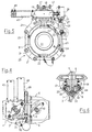
- the pipe fitting shown in the drawings is composed of two fitting parts 1 and 2 destined to be fixed to respective pipes to be coupled.
- Each one of the two fitting parts 1 and 2 comprises an external concave body 3, 4 provided with terminal flange 5, 6 turned outside for the frontal coupling with the flange of the other part of the fitting.
- each concave body 3, 4 a respective ball valve 7, 8 is turningly housed, that is made fixed to a respective driving shaft 9, 10 that is turningly supported by the concave body 3, 4 and extending outside of it.
- Both valves are passed through by a rectilinear duct 11, 12, that depending on the angular position of the respective valve can end up being lined up with the corresponding duct of the other valve and with a terminal mouth 13, 14 of the concave body 3, 4 ( Figure 1) or arranged perpendicular to the aforementioned position in order to close in that case the respective mouth 13, 14 ( Figure 3).
- valve 8 has a perfectly spherical external periphery, while the valve 7 provides a concave peripheral portion 15, in which, with both valves in a closing position, a corresponding peripheral portion of the valve 8 can be inserted. In this way the quantity of fluid which remains between the two closed valves and that is destined to be dispersed in the external environment is reduced to a minimum.
- a lever 16 At the top of the driving shaft 10 of the valve 8 a lever 16 is fixed, which through a pair of tension rods 17 ( Figure 4) is connected in an articulate way with an analogous lever 18 that is fixed to the upper part of a shaft 19, that is axially lined up with the driving shaft 9 of the valve 7 and is activated in the way that will be subsequently described in combination with it.
- a quick release coupling device that is illustrated and indicated as a whole with the numeric reference 20 in Figure 5, provides for the separable connection of the two fitting parts 1 and 2 in the facing and lined up position of Figures 1-3. It consists in a device of the type described in the US patent 4,306,739 (to be considered as incorporated in the present description), which comprises a sequence of tightening pincers 21 articulately connected by bars 22 and arrangeable across of respective circumferencial portions of the terminal flanges 5, 6 of the parts of the connection so as to form a coupling ring that is open on one end.
- a closing bar 23 of said ring that is movable on command from a closing position ( Figure 5) to an opening position of the same ring is provided.
- a series of springs housed inside the cylinder 26 and cooperating with the end of the bar 23 in the way described in the aforementioned US patent normally maintains the pawl 25 inside the cavity 27 in such a way that the axes X of the bar 23 is moved toward the axes of the fitting as regards the axes Y that ideally connects the same pawl with the fulcrum 29 of the forked lever 28.
- the aforementioned springs allow a limited sliding of the bar 23 as regards the cylinder 26 and, as a consequence, the bar 23 rotates, bringing its axes X outside of the axes Y and thus causing the rotation of the forked lever 28 and the exit of the pawl 25 from the cavity 27 of the same lever.
- the coupling ring of the two flanges 5 and 6 therefore opens, thus allowing the immediate separation of the two fitting parts 1 and 2.
- the driving shaft 10 of valve 8 is kinetically connected with a shaft 19 axially lined up with the driving shaft 9 of the valve 7. More precisely, as shown in Figure 7, on the shaft 9 a first lever 40 is keyed in 39, which through a link block 41 connection receives motion from the rod 53 of a first hydraulic cylinder 42 ( Figure 8-11). On the other hand, from the shaft 19 a reversed cup element 43 extends, which is turningly fit on the shaft 9 and is in turn keyed in 44 with a second lever 45 connected through a connecting rod 46 with a rod 47 of a second hydraulic cylinder 48 parallel to the first cylinder 42 ( Figures 4 and 8-11).
- the first lever 40 serves as a blocking element to the rotation of the second lever 45.
- the rod 47 of the second hydraulic cylinder 48 also cooperates with a third lever 50 hinged in 51, that is normally maintained elastically against a fixed support 52 ( Figures 4 and 8-10) but that can be brought far from it under the thrust of the rod 47 ( Figure 11) in order to operate in turn on the cylinder 26 ( Figure 5) and to move it to a position of release of the coupling device 20.
- the rotation of the lever 40 also causes the unlocking of the rotation of the lever 45, that the subsequent operation of the cylinder 48 can therefore set into clockwise rotation (Figure 10), that through the cup element 43, the shaft 19, the articulate parallelogram 18, 17 and 16 and the driving shaft 10 causes in turn the rotation of the valve 8 up to the closing position of Figure 3.
- the travel of the rod 47 of the cylinder 48 continues then until it provokes the operation of the lever 50 ( Figure 11) and the subsequent displacement of the cylinder 26 into the release position of the coupling device 20.
- the two fitting parts 1 and 2 can therefore separate together with the pipes to which they are attached.
Landscapes
- Engineering & Computer Science (AREA)
- General Engineering & Computer Science (AREA)
- Mechanical Engineering (AREA)
- Quick-Acting Or Multi-Walled Pipe Joints (AREA)
- Flanged Joints, Insulating Joints, And Other Joints (AREA)
Claims (3)
- Raccord de tuyaux comprenant deux pièces de raccordement (1, 2) pouvant être connectées à des tuyaux respectifs munis de clapets sphériques respectifs (7, 8), dont un (7) a une concavité, lesdits clapets (7, 8) comportant un arbre rotatif respectif (9, 10), un moyen d'accouplement (20) du type à dégagement rapide pour lesdites pièces de raccordement (1, 2) et des moyens d'interconnexion fonctionnelle (40-53) pour empêcher la fermeture du clapet sans concavité (8) avant la fermeture du clapet à concavité (7) et pour empêcher la libération du dispositif d'accouplement (20) avant la fermeture du clapet sans concavité, caractérisé en ce que lesdits moyens d'interconnexion fonctionnelle (40-53) comprennent un premier levier de commande (40) accouplé de manière mécanique à l'arbre (9) du clapet (7) à concavité pour la rotation de fermeture du clapet à concavité (7), un deuxième levier de commande (45) accouplé de manière mécanique à l'arbre (10) du clapet (8) sans concavité pour la rotation de fermeture du clapet sans concavité (8), qui est articulé sur le même axe que le premier levier (40) et qui a une rotation subordonnée au retrait d'un blocage mécanique causé par ledit premier levier (40) en position d'ouverture, un premier vérin hydraulique (42) pour commander la rotation dudit premier levier (40) vers une position de fermeture du clapet à concavité (7), et un deuxième vérin hydraulique (48) pour commander la rotation dudit deuxième levier (45) vers une position de fermeture du clapet sans concavité (8) après le retrait dudit blocage mécanique, et ensuite pour commander la libération du dispositif d'accouplement (20) des deux pièces de raccordement (1, 2),
ledit blocage mécanique étant déterminé par l'engagement dudit premier levier (40) dans une entaille radiale (49) d'un élément en forme de coupelle (43) qui tourne sur le même axe que le premier levier (40) et connecté de manière rigide audit deuxième levier (45). - Raccord de tuyaux selon la revendication 1, caractérisé en ce que ledit dispositif d'accouplement (20) comprend une séquence articulée de pinces de serrage (21) pouvant être disposées de part et d'autre de parties circonférentielles de brides terminales adjacentes (5, 6) des deux pièces de raccordement (1, 2) afin de former une bague d'accouplement ouverte sur une extrémité, et une barre (23) pour la fermeture de ladite bague qui est mobile lors de la commande d'une position de fermeture à une position d'ouverture de ladite bague.
- Raccord de tuyaux selon la revendication 2, caractérisé en ce que lesdits moyens d'interconnexion fonctionnelle (40-53) comprennent un troisième levier (50) qui peut être activé par ledit deuxième vérin (48) après la rotation dudit deuxième levier (45) et qui actionne ladite barre de fermeture (23) du dispositif d'accouplement (20).
Applications Claiming Priority (2)
| Application Number | Priority Date | Filing Date | Title |
|---|---|---|---|
| IT97MI002023A IT1294719B1 (it) | 1997-09-05 | 1997-09-05 | Raccordo per tubazioni munito di due valvole a sfera,di cui una con concavita',azionate in successione e di mezzi di accoppiamento con |
| ITMI972023 | 1997-09-05 |
Publications (3)
| Publication Number | Publication Date |
|---|---|
| EP0900967A2 EP0900967A2 (fr) | 1999-03-10 |
| EP0900967A3 EP0900967A3 (fr) | 2001-04-04 |
| EP0900967B1 true EP0900967B1 (fr) | 2004-03-24 |
Family
ID=11377829
Family Applications (1)
| Application Number | Title | Priority Date | Filing Date |
|---|---|---|---|
| EP98202911A Expired - Lifetime EP0900967B1 (fr) | 1997-09-05 | 1998-09-01 | Dispositif pour tuyaux avec deux soupapes à bille et comprenant des moyens à décrochage rapide |
Country Status (5)
| Country | Link |
|---|---|
| US (1) | US6056011A (fr) |
| EP (1) | EP0900967B1 (fr) |
| JP (1) | JP3601983B2 (fr) |
| DE (1) | DE69822575T2 (fr) |
| IT (1) | IT1294719B1 (fr) |
Families Citing this family (16)
| Publication number | Priority date | Publication date | Assignee | Title |
|---|---|---|---|---|
| JP4499872B2 (ja) * | 2000-05-17 | 2010-07-07 | アイシン精機株式会社 | 弁装置 |
| US6609532B1 (en) | 2001-03-15 | 2003-08-26 | Dialysis Systems, Inc. | Rotational connecting valve with quick disconnect |
| US20020166989A1 (en) * | 2001-05-08 | 2002-11-14 | Peterson Michael J. | Valve assembly |
| ITMI20022197A1 (it) | 2002-10-16 | 2004-04-17 | Lorenzo Bormioli | Connettore per tubazioni per uso criogenico |
| EP1922506B1 (fr) * | 2005-08-09 | 2013-06-26 | FMC Technologies S.A. | Système de déconnexion d'urgence |
| JP4754340B2 (ja) * | 2005-12-02 | 2011-08-24 | ニイガタ・ローディング・システムズ株式会社 | 流体荷役装置における緊急切り離し装置 |
| JP5216350B2 (ja) * | 2008-02-05 | 2013-06-19 | ニイガタ・ローディング・システムズ株式会社 | 流体荷役装置における緊急切り離し装置 |
| US8132781B2 (en) * | 2009-04-28 | 2012-03-13 | Eaton Corporation | Interlock system for valve coupling |
| JP2011021672A (ja) * | 2009-07-15 | 2011-02-03 | Ihi Corp | ボールバルブ及びボールバルブのリーク検査方法 |
| NO2473769T3 (fr) * | 2009-09-03 | 2018-05-26 | ||
| US8662108B2 (en) | 2011-02-18 | 2014-03-04 | Eaton Corporation | Quick connect fluid coupling |
| US8967177B2 (en) * | 2011-07-01 | 2015-03-03 | Eaton Corporation | Sequenced ball valve coupling |
| US8887762B2 (en) | 2011-07-01 | 2014-11-18 | Eaton Corporation | Quick connect coupling with nested ball valves |
| GB2514996B (en) * | 2013-04-10 | 2016-02-10 | Alpha Process Control | Breakaway coupling |
| PL234666B1 (pl) * | 2018-04-26 | 2020-03-31 | Aquael Janusz Jankiewicz Spolka Z Ograniczona Odpowiedzialnoscia | Filtr wody do akwarium |
| CA3101533C (fr) * | 2018-06-06 | 2023-05-23 | Staubli Hamburg Gmbh | Coupleur hydraulique |
Family Cites Families (11)
| Publication number | Priority date | Publication date | Assignee | Title |
|---|---|---|---|---|
| IT1109855B (it) * | 1979-01-08 | 1985-12-23 | Bormioli Giorgio | Dispositivo di collegamento a sgancio rapido per componenti idraulici flangiati |
| JPS58149406A (ja) * | 1982-02-26 | 1983-09-05 | Niigata Eng Co Ltd | 油圧シリンダの安全装置付チェックバルブ |
| FR2581732A1 (fr) * | 1985-05-10 | 1986-11-14 | Fremy Raoul | Dispositif d'arret pour fluides a double obturateur tournant |
| JPH0414685Y2 (fr) * | 1985-07-25 | 1992-04-02 | ||
| IT1188451B (it) * | 1986-03-17 | 1988-01-14 | Giorgio Bormioli | Sistema combinato di stacco rapido di sicurezza e valvole di controllo per tubazioni |
| JPH0223600Y2 (fr) * | 1986-06-26 | 1990-06-27 | ||
| JPH0712796Y2 (ja) * | 1991-11-15 | 1995-03-29 | 株式会社新潟鉄工所 | 流体荷役装置等における緊急切離し装置 |
| US5332001A (en) * | 1993-08-02 | 1994-07-26 | J. C. Carter Company, Inc. | Sexless ball valve coupling |
| FR2714709B1 (fr) * | 1994-01-05 | 1996-02-02 | Fmc Corp | Accouplement à ouverture d'urgence alimenté par une double vanne à boisseau sphérique à débordement nul. |
| US5402825A (en) * | 1994-06-09 | 1995-04-04 | Aeroquip Corporation | Ball valve coupling |
| US5488972A (en) * | 1995-02-13 | 1996-02-06 | Aeroquip Corporation | Ball valve coupling |
-
1997
- 1997-09-05 IT IT97MI002023A patent/IT1294719B1/it active IP Right Grant
-
1998
- 1998-08-28 US US09/141,559 patent/US6056011A/en not_active Expired - Fee Related
- 1998-09-01 DE DE69822575T patent/DE69822575T2/de not_active Expired - Fee Related
- 1998-09-01 EP EP98202911A patent/EP0900967B1/fr not_active Expired - Lifetime
- 1998-09-04 JP JP25022598A patent/JP3601983B2/ja not_active Expired - Fee Related
Also Published As
| Publication number | Publication date |
|---|---|
| ITMI972023A1 (it) | 1999-03-05 |
| EP0900967A2 (fr) | 1999-03-10 |
| DE69822575T2 (de) | 2005-03-31 |
| DE69822575D1 (de) | 2004-04-29 |
| US6056011A (en) | 2000-05-02 |
| IT1294719B1 (it) | 1999-04-12 |
| JPH11153282A (ja) | 1999-06-08 |
| JP3601983B2 (ja) | 2004-12-15 |
| EP0900967A3 (fr) | 2001-04-04 |
Similar Documents
| Publication | Publication Date | Title |
|---|---|---|
| EP0900967B1 (fr) | Dispositif pour tuyaux avec deux soupapes à bille et comprenant des moyens à décrochage rapide | |
| RU2121102C1 (ru) | Соединение с двумя шаровыми затворами, обеспечивающее экстренное разъединение, исключающее утечку | |
| RU96116132A (ru) | Соединение с двумя шаровыми затворами, обеспечивающее экстренное разъединение, исключающее утечку | |
| KR20100042231A (ko) | 진공밸브 | |
| US3902694A (en) | Swinging spherical gate valve and double seal quick disconnect coupling | |
| US4519411A (en) | Emergency disconnector for fluid loading and unloading lines | |
| US5492148A (en) | Rinsing assembly with swivel actuating valve | |
| GB2064730A (en) | Improvements in pipe line shut-off valves with a leakage safety device | |
| IL165307A (en) | Shut-off fitting | |
| EP1552208B1 (fr) | Connecteur de securite pour tuyauterie a couplage et desserrage rapides | |
| US11906098B2 (en) | Dual control emergency release system | |
| GB2134206A (en) | Closure for pipes or vessels | |
| JP5952286B2 (ja) | 接続器/切断器のバルブを制御するための装置 | |
| JP2787152B2 (ja) | 弁の密封装置 | |
| EP1120596B1 (fr) | Accouplement de secours en response à une forte traction axiale | |
| JPS62220796A (ja) | 配管用急速安全連結解除機構と制御弁の組合わせ装置 | |
| WO1995033158A1 (fr) | Ensemble raccord a soupapes | |
| JPH0646880Y2 (ja) | 流体荷役装置における緊急離脱装置 | |
| AU2003286139A1 (en) | Pipe connector for cryogenic use | |
| GB2098296A (en) | Pipe couplings | |
| JP2026009081A (ja) | クランプカラー | |
| JPS63500733A (ja) | 加圧ガスタンク,特に産業用車輌の空気タンクから凝縮物を排出するための自動制御装置及びその弁装置 | |
| CZ2418U1 (cs) | Dvojčinná průmyslová armatura | |
| HK1122533B (en) | Gripping device for a robot or a gantry loader | |
| HK1122533A1 (en) | Gripping device for a robot or a gantry loader |
Legal Events
| Date | Code | Title | Description |
|---|---|---|---|
| PUAI | Public reference made under article 153(3) epc to a published international application that has entered the european phase |
Free format text: ORIGINAL CODE: 0009012 |
|
| AK | Designated contracting states |
Kind code of ref document: A2 Designated state(s): DE FR GB IT |
|
| AX | Request for extension of the european patent |
Free format text: AL;LT;LV;MK;RO;SI |
|
| PUAL | Search report despatched |
Free format text: ORIGINAL CODE: 0009013 |
|
| AK | Designated contracting states |
Kind code of ref document: A3 Designated state(s): AT BE CH CY DE DK ES FI FR GB GR IE IT LI LU MC NL PT SE |
|
| AX | Request for extension of the european patent |
Free format text: AL;LT;LV;MK;RO;SI |
|
| 17P | Request for examination filed |
Effective date: 20010917 |
|
| AKX | Designation fees paid |
Free format text: DE FR GB IT |
|
| 17Q | First examination report despatched |
Effective date: 20030306 |
|
| GRAP | Despatch of communication of intention to grant a patent |
Free format text: ORIGINAL CODE: EPIDOSNIGR1 |
|
| GRAS | Grant fee paid |
Free format text: ORIGINAL CODE: EPIDOSNIGR3 |
|
| GRAA | (expected) grant |
Free format text: ORIGINAL CODE: 0009210 |
|
| AK | Designated contracting states |
Kind code of ref document: B1 Designated state(s): DE FR GB IT |
|
| REG | Reference to a national code |
Ref country code: GB Ref legal event code: FG4D |
|
| REF | Corresponds to: |
Ref document number: 69822575 Country of ref document: DE Date of ref document: 20040429 Kind code of ref document: P |
|
| ET | Fr: translation filed | ||
| PLBE | No opposition filed within time limit |
Free format text: ORIGINAL CODE: 0009261 |
|
| STAA | Information on the status of an ep patent application or granted ep patent |
Free format text: STATUS: NO OPPOSITION FILED WITHIN TIME LIMIT |
|
| 26N | No opposition filed |
Effective date: 20041228 |
|
| PGFP | Annual fee paid to national office [announced via postgrant information from national office to epo] |
Ref country code: GB Payment date: 20080806 Year of fee payment: 11 |
|
| PGFP | Annual fee paid to national office [announced via postgrant information from national office to epo] |
Ref country code: DE Payment date: 20080930 Year of fee payment: 11 |
|
| GBPC | Gb: european patent ceased through non-payment of renewal fee |
Effective date: 20090901 |
|
| PG25 | Lapsed in a contracting state [announced via postgrant information from national office to epo] |
Ref country code: DE Free format text: LAPSE BECAUSE OF NON-PAYMENT OF DUE FEES Effective date: 20100401 |
|
| PG25 | Lapsed in a contracting state [announced via postgrant information from national office to epo] |
Ref country code: GB Free format text: LAPSE BECAUSE OF NON-PAYMENT OF DUE FEES Effective date: 20090901 |
|
| REG | Reference to a national code |
Ref country code: FR Ref legal event code: PLFP Year of fee payment: 19 |
|
| REG | Reference to a national code |
Ref country code: FR Ref legal event code: PLFP Year of fee payment: 20 |
|
| PGFP | Annual fee paid to national office [announced via postgrant information from national office to epo] |
Ref country code: IT Payment date: 20170920 Year of fee payment: 20 Ref country code: FR Payment date: 20170927 Year of fee payment: 20 |