EP0900979A1 - Beleuchtungssystem - Google Patents
Beleuchtungssystem Download PDFInfo
- Publication number
- EP0900979A1 EP0900979A1 EP98500195A EP98500195A EP0900979A1 EP 0900979 A1 EP0900979 A1 EP 0900979A1 EP 98500195 A EP98500195 A EP 98500195A EP 98500195 A EP98500195 A EP 98500195A EP 0900979 A1 EP0900979 A1 EP 0900979A1
- Authority
- EP
- European Patent Office
- Prior art keywords
- light
- lighted
- lighting system
- cables
- optical fibre
- Prior art date
- Legal status (The legal status is an assumption and is not a legal conclusion. Google has not performed a legal analysis and makes no representation as to the accuracy of the status listed.)
- Ceased
Links
- 239000000463 material Substances 0.000 claims abstract description 12
- 239000013307 optical fiber Substances 0.000 claims abstract description 12
- 230000005540 biological transmission Effects 0.000 claims description 2
- 238000012423 maintenance Methods 0.000 description 5
- 239000007789 gas Substances 0.000 description 4
- 230000000694 effects Effects 0.000 description 2
- 239000007858 starting material Substances 0.000 description 2
- 230000002411 adverse Effects 0.000 description 1
- 230000032683 aging Effects 0.000 description 1
- 239000012141 concentrate Substances 0.000 description 1
- 238000010276 construction Methods 0.000 description 1
- 238000005034 decoration Methods 0.000 description 1
- 230000007423 decrease Effects 0.000 description 1
- 230000018109 developmental process Effects 0.000 description 1
- 238000010586 diagram Methods 0.000 description 1
- 239000011521 glass Substances 0.000 description 1
- 239000011261 inert gas Substances 0.000 description 1
- 238000012986 modification Methods 0.000 description 1
- 230000004048 modification Effects 0.000 description 1
- 229910052754 neon Inorganic materials 0.000 description 1
- GKAOGPIIYCISHV-UHFFFAOYSA-N neon atom Chemical compound [Ne] GKAOGPIIYCISHV-UHFFFAOYSA-N 0.000 description 1
- 230000005855 radiation Effects 0.000 description 1
- 230000035882 stress Effects 0.000 description 1
- 239000002699 waste material Substances 0.000 description 1
Images
Classifications
-
- G—PHYSICS
- G02—OPTICS
- G02B—OPTICAL ELEMENTS, SYSTEMS OR APPARATUS
- G02B6/00—Light guides; Structural details of arrangements comprising light guides and other optical elements, e.g. couplings
- G02B6/0001—Light guides; Structural details of arrangements comprising light guides and other optical elements, e.g. couplings specially adapted for lighting devices or systems
- G02B6/0005—Light guides; Structural details of arrangements comprising light guides and other optical elements, e.g. couplings specially adapted for lighting devices or systems the light guides being of the fibre type
- G02B6/0006—Coupling light into the fibre
Definitions
- the lighting system of the present invention uses an optical fibre cable between the light emitter, of desired power, color and features, and the final lighted element which can be a tube or body of metacrylate or similar material with translucent properties, which will be completely lighted.
- the currently used system consists of glass tubes containing an inert gas such as neon covered with a fluorescent material emitting a light due to ultraviolet radiations produced within the tube when an electrical discharge takes place inside a low pressure gas.
- an inert gas such as neon
- a fluorescent material emitting a light due to ultraviolet radiations produced within the tube when an electrical discharge takes place inside a low pressure gas.
- Elements required for a proper operation are a starter, a power source and specific tube holding means.
- This type of lighting system has some inconveniences such as the useful life of tubes, the gas and its components, which is rather limited specially when affected by adverse weather conditions that shorten the useful life or requiring an additional protection and increasing the cost of equipment.
- Another lighting system consists of electronic transformers 220V/20,000V, producing with this high voltage a continuous voltaic arc, thus producing a light emission to illuminate an area.
- This system presents the problems derived from the use of high voltages with respect to poor connections and splices that produce arcs and sparks causing the aging of materials, faults, etc., as well as high riska of electrical discharges on human or fires.
- this system requires a full protection against dirt and humidity for the efficiency decreases considerably, this system being expensive with respect to transformers and power consumption.
- a known development consists of making the letters, figures and grphics of lighted advertatoriums with optical fiber, based on long lines of this material, configurating a required pattern and being connected to the wires of the lighting source.
- the main disadvantage with such a system is the complicated network of wires, all connected to the power source. Also, the supporting board requires a great plurality of holes to allow the passage of the wires, thus affecting the appearance and construction of the lighting panel. Also, due to the high cost of the optical fiber, the system total cost turns out to be extremely expensive.
- the lighting system of present invention essentially consists of a lighting source connected to a power source, with a corresponding luminaire which helps keeping the light beam in a given alignment and path.
- a translucent body is coupled to said luminaire, said translucent body preferably being made of metacrylate or similar material with low cost and good properties such as light weight, high strength and transparency.
- Said plastic body will have holes, copnnections or the required means for the attachment to it of optical fibre cable.
- Said optical fibre cable will extend on to another body, preferably of metacrylate or similar material with respect to features and properties, which body will illuminate when receiving the light beam by means of the optical fibre cable.
- the lighting source may be of any type or capacity as required by the system requirements.
- the average useful life of said system is considerably longer than that of known lighting systems, for there is no practical wear, no high voltages or gases, tec., making an efficient and economic system with minimum maintenance, with practically no spares.
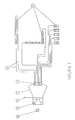
- a light source (1) preferably placed inside a luminaire (2) and a body (3), attached to said luminaire, of an adequate size provided with the necessary means for the connection of the optical fibre cables (4), extended to the connection point of the element (5) to be lighted.
- the lighting source (1) will be as required by the system with respect to power, intensity, etc., like incandescent lamps, low consumption cool bulbs, etc., and will be connected to the power source (6) such as an AC source, batteries, etc.
- the luminaire (2) will be of the enclosed type to avoid light losses and, at the same time, should concentrate the light beam on the output body (3), of adequate dimensions to house all optical fibre cable connections (4) in consonance with the required assembly, this body (3) being the only output for the light produced by the luminaire, said body being made of a light, strong and translucent plastic material. Said system having the possibility to have more than one output (3), depending on the system needs and on the luminaire dimensions (2).
- the optical fibre cable (4) is used as transmission means between the light beam produced by the light source (1) through the output body (3) and the element to be lighted (5), with the advantage that the light losses in these cables are practically nil, and said cables are provided with a protection or cover.
- the lighted elements can adopt the configuration ofhanrails, letters, decoration elements, floor signals, etc., since the plastic material they are made of can support high stresses.
- the mounting and operation of the lighting system of the present invention is rather easy, requiring only one light source (1), with the emission of a white or color light, depending on the desired effect on the lighted elements (5).
- Said light source will preferably be enclosed in a corresponding luminaire (2), which conveys the light beam to the output body (3), to which all optical fibre cables (4) have been connected to, as required to light all lighted elements (5). Therefore, it is recomended to reduce as much as posible the distance from the light source (1) to the lighted elements (5) in order to have minimum cable lengths (4).
- more than one light receiving point (more than one cable) can be arranged in order to obtain a proper light distribution.
- the system makes it possible to introduce between the light source (1) and the output body (3) any means (7) capable of altering the color or shade of the light emitted.
- the lighting system of the present invention is a low cost, almost maintenance free system producing colorful effects.
Landscapes
- Physics & Mathematics (AREA)
- General Physics & Mathematics (AREA)
- Optics & Photonics (AREA)
- Non-Portable Lighting Devices Or Systems Thereof (AREA)
- Light Guides In General And Applications Therefor (AREA)
Applications Claiming Priority (2)
| Application Number | Priority Date | Filing Date | Title |
|---|---|---|---|
| ES9701899 | 1997-09-05 | ||
| ES9701899A ES2127156B1 (es) | 1997-09-05 | 1997-09-05 | Sistema luminoso. |
Publications (1)
| Publication Number | Publication Date |
|---|---|
| EP0900979A1 true EP0900979A1 (de) | 1999-03-10 |
Family
ID=8300549
Family Applications (1)
| Application Number | Title | Priority Date | Filing Date |
|---|---|---|---|
| EP98500195A Ceased EP0900979A1 (de) | 1997-09-05 | 1998-09-03 | Beleuchtungssystem |
Country Status (2)
| Country | Link |
|---|---|
| EP (1) | EP0900979A1 (de) |
| ES (1) | ES2127156B1 (de) |
Citations (5)
| Publication number | Priority date | Publication date | Assignee | Title |
|---|---|---|---|---|
| US3564231A (en) * | 1968-09-26 | 1971-02-16 | Poly Optics | Illumination device |
| EP0058574A2 (de) * | 1981-02-17 | 1982-08-25 | Fuji Photo Optical Co., Ltd. | Verfahren und Vorrichtung zur Wiederherstellung der Lichtübertragungseigenschaften eines bildübertragenden optischen Faserbündels zur Verwendung in einem Faserendoskop |
| JPH01211705A (ja) * | 1988-02-19 | 1989-08-24 | Sakae Riken Kogyo Kk | 光ファイバーによる発光体の光源装置 |
| GB2266970A (en) * | 1992-05-15 | 1993-11-17 | Andrew John Neave | A light distribution unit for use with a light projector which projects light via light guides |
| US5606637A (en) * | 1995-07-21 | 1997-02-25 | Dolby; Timothy S. | Decorative fiber optic light fixture and methods of making same |
Family Cites Families (3)
| Publication number | Priority date | Publication date | Assignee | Title |
|---|---|---|---|---|
| US4226504A (en) * | 1976-03-15 | 1980-10-07 | Akzona Incorporated | Protection of optical fibers |
| US5013109A (en) * | 1989-11-06 | 1991-05-07 | Fiber Tech, Inc. | Modular system for decorative lighting |
| US5381501A (en) * | 1994-01-27 | 1995-01-10 | General Motors Corporation | Fiber optic bundle connector including a hollow cone and a terminal block |
-
1997
- 1997-09-05 ES ES9701899A patent/ES2127156B1/es not_active Expired - Fee Related
-
1998
- 1998-09-03 EP EP98500195A patent/EP0900979A1/de not_active Ceased
Patent Citations (5)
| Publication number | Priority date | Publication date | Assignee | Title |
|---|---|---|---|---|
| US3564231A (en) * | 1968-09-26 | 1971-02-16 | Poly Optics | Illumination device |
| EP0058574A2 (de) * | 1981-02-17 | 1982-08-25 | Fuji Photo Optical Co., Ltd. | Verfahren und Vorrichtung zur Wiederherstellung der Lichtübertragungseigenschaften eines bildübertragenden optischen Faserbündels zur Verwendung in einem Faserendoskop |
| JPH01211705A (ja) * | 1988-02-19 | 1989-08-24 | Sakae Riken Kogyo Kk | 光ファイバーによる発光体の光源装置 |
| GB2266970A (en) * | 1992-05-15 | 1993-11-17 | Andrew John Neave | A light distribution unit for use with a light projector which projects light via light guides |
| US5606637A (en) * | 1995-07-21 | 1997-02-25 | Dolby; Timothy S. | Decorative fiber optic light fixture and methods of making same |
Non-Patent Citations (1)
| Title |
|---|
| PATENT ABSTRACTS OF JAPAN vol. 013, no. 520 (P - 963) 21 November 1989 (1989-11-21) * |
Also Published As
| Publication number | Publication date |
|---|---|
| ES2127156A1 (es) | 1999-04-01 |
| ES2127156B1 (es) | 1999-12-16 |
Similar Documents
| Publication | Publication Date | Title |
|---|---|---|
| US7357528B2 (en) | CCFL illuminated device and method of use | |
| US7114830B2 (en) | LED replacement for fluorescent lighting | |
| CA2285507C (en) | Phosphorous fluorescent light assembly excited by light emitting diodes | |
| US6616310B1 (en) | CCFL illuminated device | |
| FI110636B (fi) | Järjestely valaisimen yhteydessä ja valaisin | |
| US7249865B2 (en) | Combination fluorescent and LED lighting system | |
| US7549782B2 (en) | Semiconductor light source configured as a light tube | |
| US6636686B1 (en) | Braided optical fiber bundles | |
| US20050184667A1 (en) | CCFL illuminated device and method of use | |
| US20090261706A1 (en) | LED Replacement Light Tube for Fluorescent Light Fixture | |
| DE69933374D1 (de) | Operationsleucthtensteuerung | |
| GB2396686A (en) | Christmas tree having fibre optic illumination | |
| CA2089543A1 (en) | Lighting apparatus | |
| EP0495866B1 (de) | Beleuchtungsvorrichtung | |
| MXPA04007185A (es) | Aparato y metodo de fabricacion para iluminacion de orilla. | |
| ES2175037T3 (es) | Lamparas y sistemas de descarga de gas. | |
| EP0900979A1 (de) | Beleuchtungssystem | |
| US20040056576A1 (en) | Protected lamp device | |
| KR200213230Y1 (ko) | 광섬유를 이용한 실외용 조명기구 | |
| JPH08329712A (ja) | 省エネルギ型照明装置 | |
| RU9046U1 (ru) | Сигнальное оптическое устройство | |
| KR200204174Y1 (ko) | 조명수단을구비한진열가구 | |
| KR970037481A (ko) | 방전 전구와 광섬유를 사용하는 리어 콤비네이션 | |
| KR200191428Y1 (ko) | 사찰용 등 | |
| Denton | Bright future |
Legal Events
| Date | Code | Title | Description |
|---|---|---|---|
| PUAI | Public reference made under article 153(3) epc to a published international application that has entered the european phase |
Free format text: ORIGINAL CODE: 0009012 |
|
| AK | Designated contracting states |
Kind code of ref document: A1 Designated state(s): BE DE FR GB IT NL |
|
| AX | Request for extension of the european patent |
Free format text: AL;LT;LV;MK;RO;SI |
|
| AKX | Designation fees paid |
Free format text: BE DE FR GB IT NL |
|
| 17P | Request for examination filed |
Effective date: 19991007 |
|
| 17Q | First examination report despatched |
Effective date: 20031125 |
|
| APBN | Date of receipt of notice of appeal recorded |
Free format text: ORIGINAL CODE: EPIDOSNNOA2E |
|
| APAF | Appeal reference modified |
Free format text: ORIGINAL CODE: EPIDOSCREFNE |
|
| APAF | Appeal reference modified |
Free format text: ORIGINAL CODE: EPIDOSCREFNE |
|
| APBT | Appeal procedure closed |
Free format text: ORIGINAL CODE: EPIDOSNNOA9E |
|
| STAA | Information on the status of an ep patent application or granted ep patent |
Free format text: STATUS: THE APPLICATION HAS BEEN REFUSED |
|
| 18R | Application refused |
Effective date: 20060414 |