EP0901039B1 - Verfahren zum Übergang von einer Emulsions-Charge zur anderen unter Verwendung eines passiven Verflüssigungsapparates - Google Patents
Verfahren zum Übergang von einer Emulsions-Charge zur anderen unter Verwendung eines passiven Verflüssigungsapparates Download PDFInfo
- Publication number
- EP0901039B1 EP0901039B1 EP98202806A EP98202806A EP0901039B1 EP 0901039 B1 EP0901039 B1 EP 0901039B1 EP 98202806 A EP98202806 A EP 98202806A EP 98202806 A EP98202806 A EP 98202806A EP 0901039 B1 EP0901039 B1 EP 0901039B1
- Authority
- EP
- European Patent Office
- Prior art keywords
- batch
- liquefaction apparatus
- rate
- flow
- mpl
- Prior art date
- Legal status (The legal status is an assumption and is not a legal conclusion. Google has not performed a legal analysis and makes no representation as to the accuracy of the status listed.)
- Expired - Lifetime
Links
Images


Classifications
-
- G—PHYSICS
- G03—PHOTOGRAPHY; CINEMATOGRAPHY; ANALOGOUS TECHNIQUES USING WAVES OTHER THAN OPTICAL WAVES; ELECTROGRAPHY; HOLOGRAPHY
- G03C—PHOTOSENSITIVE MATERIALS FOR PHOTOGRAPHIC PURPOSES; PHOTOGRAPHIC PROCESSES, e.g. CINE, X-RAY, COLOUR, STEREO-PHOTOGRAPHIC PROCESSES; AUXILIARY PROCESSES IN PHOTOGRAPHY
- G03C1/00—Photosensitive materials
- G03C1/005—Silver halide emulsions; Preparation thereof; Physical treatment thereof; Incorporation of additives therein
- G03C1/025—Physical treatment of emulsions, e.g. by ultrasounds, refrigeration or pressure
-
- B—PERFORMING OPERATIONS; TRANSPORTING
- B29—WORKING OF PLASTICS; WORKING OF SUBSTANCES IN A PLASTIC STATE IN GENERAL
- B29B—PREPARATION OR PRETREATMENT OF THE MATERIAL TO BE SHAPED; MAKING GRANULES OR PREFORMS; RECOVERY OF PLASTICS OR OTHER CONSTITUENTS OF WASTE MATERIAL CONTAINING PLASTICS
- B29B13/00—Conditioning or physical treatment of the material to be shaped
- B29B13/02—Conditioning or physical treatment of the material to be shaped by heating
- B29B13/022—Melting the material to be shaped
-
- B—PERFORMING OPERATIONS; TRANSPORTING
- B29—WORKING OF PLASTICS; WORKING OF SUBSTANCES IN A PLASTIC STATE IN GENERAL
- B29C—SHAPING OR JOINING OF PLASTICS; SHAPING OF MATERIAL IN A PLASTIC STATE, NOT OTHERWISE PROVIDED FOR; AFTER-TREATMENT OF THE SHAPED PRODUCTS, e.g. REPAIRING
- B29C35/00—Heating, cooling or curing, e.g. crosslinking or vulcanising; Apparatus therefor
- B29C35/02—Heating or curing, e.g. crosslinking or vulcanizing during moulding, e.g. in a mould
- B29C35/04—Heating or curing, e.g. crosslinking or vulcanizing during moulding, e.g. in a mould using liquids, gas or steam
- B29C35/041—Heating or curing, e.g. crosslinking or vulcanizing during moulding, e.g. in a mould using liquids, gas or steam using liquids
Definitions
- the present invention relates generally to batch liquefaction of solid materials used in the preparation of photographic emulsions and, more particularly, to processes for partially mixing sequential batches to smooth the transition from batch to batch and prevent unacceptable variations in the coated product to be produced therewith.
- Typical emulsion coating operations require liquid kettle blending to smooth batch-to-batch variability during long coating events.
- Conventional continuous liquefaction technology requires quick chilling, and/or pelletization, and solid blending equipment to pre-blend the emulsion in solid form. This technology is described in U.S. Patent No. 5,182,190.
- U.S. Patent No. 5,523,537 describes a modified passive liquefaction system.
- a liquefying apparatus having a hopper which includes an upper and lower section is described.
- the upper section is adapted to receive a meltable solid material and has a coiled tube disposed therein.
- solid material supported thereon is melted and allowed to pass therethrough such that the liquefied product is stored in the lower section of the hopper and subsequently drawn off.
- Use of this technology with U.S. Patent 5,182,190 allows one to first blend the solid material, and then passively liquefy the gelled material.
- long coatings require the use of many batches of product to produce a continuous coating.
- Long refers to the length of time required to perform the operation.
- a long coating in a film/paper plant can be a two to three day operation. In dedicated plants a long coating operation may last seven to ten days. It is not uncommon that the sensitometric parameters between batches are variable. If each batch is coated sequentially and in an end-to-end manner, unacceptable variations to the coated product can be produced. The variations in the sensitometric parameters of consecutive batches can result in step changes in the coated product which cannot be compensated for fast enough by a metered dye feedback system.
- Melt drift refers to a drift in the sensitometry of a melt over time. Photographic emulsions tend not to be particularly stable and as a result of liquid hold times of up to seven hours in a melt kettle, emulsion chemistry changes due to the solution temperature which, in turn, yields a change in the sensitometry.
- the modified passive liquid in-line segmented blender described in U.S. Patent No. 5,374,120 is designed to blend one to four batches of product by simultaneously liquefying the batches into a surge pot.
- the solutions are blended within the surge pot by means of a kettle type mixer.
- the process achieves blending by liquefying the emulsion in each of the four quadrants.
- the liquefaction rate of each quadrant is roughly equal. Total liquefaction of all four quadrants is dependent on coating machine demand. Transitions are achieved in four steps of 25% each and independent solution flow rates cannot be regulated.
- the segmented blender requires hand loading a product into each quadrant and is labor intensive.
- an object of the present invention to provide a method for blending sequential batches of melt which eliminates the problem of melt drift associated with melt hold.
- Still another object of the present invention is to provide a method for blending sequential melts which allows for the continuous transition from one melt to the next.
- Yet another object of the present invention is to provide a method for blending sequential batches of melts which allows for the independent liquefaction of two products.
- each modified liquefaction apparatus has a metering pump associated therewith to draw melt therefrom and deliver the melt to a surge pot from which the melt can be pumped to the coating operation.
- Each metering pump is flow controlled and the discharge lines combined to allow for static in-line mixing of the two metering pump discharges.
- a control system allows for regulated flow from each of the metering pumps such that the transition of drawing from the first liquefaction apparatus to the second liquefaction apparatus occurs well in advance of the exhaustion of the melt in the liquefaction apparatus.
- total flow from the first liquefaction apparatus is constantly decreased and total flow from the second liquefaction apparatus is constantly increased with total flow from the two liquefaction apparatus remaining the same.
- This regulation of the transition allows for precise timing and control of the actual transition and controlled solution flow rates independent of melting during the transition itself. This, in turn, allows for waste to be minimized.
- FIG. 1 there is shown a flow schematic of the system which can be used to practice the method of the present invention.
- This system includes a first modified passive liquefaction apparatus 10 and a second modified passive liquefaction apparatus 12 hereinafter referred to as "first MPL 10" and “second MPL 12", respectively.
- Each MPL 10, 12 includes a hopper 14 having a heating coil 16 which is disposed therein and connected to the hopper 14 in a conventional manner.
- the coil 16 supports solid materials such as solid chunks of aqueous gelatin, which are fed into the hopper 14. The solid materials rest on the coil 16 until they are heated by the coil 16 and transformed into a liquid state.
- Heating coil 16 actually consists of two or more lengths of spiral wound tubing which act to transfer heat from the heating water to the solid product and induce liquefaction.
- the upper portion of the hopper 14 includes vertically oriented walls 18 which prevent the solid chunks of aqueous gelatin from adhering to the wall surface.
- a hot water supply (not shown) delivers hot water to heating coil 16 via valve 20 and inlet pipe 22.
- Hot water pumped through heating coil 16 provides the heat needed to melt the gelatin contacting heating coil 16.
- Liquefied gelatin drops through coil 16 into the lower portion of hopper 14. Any solid chunks of gelatin or foreign objects which might pass through coil 16 are captured on screen 24.
- the lower portion of hopper 16 includes a sump 26 where liquefied gelatin is collected. Disposed in the lower section of hopper 14 is a liquid level sensor 28.
- the liquid level sensor 28 is used to indicate when sump 26 is full to a computer based control system 29.
- a high level indication from liquid level sensor 28 serves to close valve 20 to interrupt further melting of the gelatin.
- outlet pipe 32 There is an outlet pipe 32 from the first MPL 10 and there is an outlet pipe 34 from second MPL 12. Each outlet pipe 32, 34 actually connects to the sump portion 26 of the respective MPLs 10, 12.
- Outlet pipe 32 delivers liquefied gelatin via gravity to a first gear pump 36.
- Outlet pipe 34 delivers liquefied gelatin to the second gear pump 38 via gravity.
- the discharge pipe 40 from first gear pump 36 connects to MPL selection valve 42.
- the discharge pipe 44 from second gear pump 38 also connects to MPL selection valve 42.
- MPL selection valve 42 is a multi-port plug valve enabling, through operation of the computer control system 29, discharge from either the first MPL 10 or second MPL 12 to pass therethrough, or to combine such discharges into a single intermixed stream at a particular ratio.
- the outlet 46 from MPL selection valve 42 connects to a filter selection valve 48.
- Filter selection valve 48 allows diversion of liquid flow therethrough to a selected one of two filters 50.
- the outlets from each of the filters 50 connect to a filter divertor valve 52.
- the filter selection valve 48 and the filter divertor valve 52 are used to isolate each of the two filters 50 so that one filter 50 can be purged, cleaned and/or removed without disturbing operation of the overall process.
- Filters 50 are preferably sized to remove particulates ranging in size from about 10 to 20 microns and greater.
- a pipe connects filter divertor valve 52 with a centrifugal vacuum degasser valve which serves to remove any remaining entrained air from the liquefied gelatin.
- the outlet pipe 56 from the centrifugal vacuum degasser valve 54 can deliver the liquefied gelatin to a surge pot 58.
- a gear pump 60 is provided in the outlet pipe 62 from surge pot 58 to pump the liquefied gelatin to the coating operation (not shown).
- a line flush valve 64 is provided in outlet pipe 62.
- Each of the gear pumps 36, 38 are positive displacement pumps. As such, gear pumps 36, 38 are used to regulate and control the flow of solution from their respective MPLs 10, 12.
- the computer 29 is connected to both flow indicator controllers 68, 72. Computer 29, through operation of software, controls the percentage of flow from each of the gear pumps 36, 38 and ensures that the combined flow, that is the total flow from both gear pumps 36, 38 remains the same.
- the system of the present invention also includes a level indicator/controller 76 in surge pot 58 which signals the computer 29.
- flow elements 66, 70 which may be either mass or volumetric type flow elements, are used to measure the solution flow rate and control the solution flow rate in a flow loop with their respective gear pumps 36, 38.
- flow indicator/controller 68, 72 receives a flow signal. The flow signal is based on the level in surge pot 58 and, in general, matches demand for the coating operation downstream.
- the total flow from both gear pumps 36, 38 as controlled by flow indicator/controllers 68, 72 equals the coat flow in the downstream operation.
- the sensitometric variability (particularly emulsion speed) between batches can be assessed prior to coating.
- Batches within the sensitometric acceptance level should not need transitioning but due to the uncertainty of measurement of the sensitometric parameters, batches have to be processed, that is smoothed, as if there is a large difference from batch to batch.
- each MPL 10, 12 continuously melts the solid gelatin using hot water coil set at 54.4°C. As soon as the product liquefies around the heating coil 16, the liquefied product drops away from the heat source to collect in the sump 26.
- the temperature in the sump 26 may vary with flow demand but should be close to about 43.3°C. To maintain this temperature and to correct for variations caused by demand changes, an in-line active heat exchanger 78 is used.
- the MPLs 10, 12 are set on weigh scales (not shown). Each MPL 10, 12 is calibrated to the same weight so that at each stage of operation, the actual contents can be established. Transitioning automatically starts on the weight on the "old" or spent MPL 10, 12. This should include a small contingent weight.
- Initial flow for the "new" MPL 10, 12 is preferably set at 50 cc/min. for three minutes before ramping starts. By “ramping" what is meant is the gradual increase in flow from the new MPL 10, 12 and the gradual decrease in flow from the old MPL 10, 12.
- the flow rate from the "new" MPL 10, 12 will change to 5% of the total coat flow and then start the transition rate. If 5% of the coat flow is less than 50 cc/min., the gear pump 36, 38 for the "new" MPL 10, 12 will run at 50 cc/min. until that point in time is reached on the transition curve where flow demand from the new MPL 10, 12 reaches 50 cc/min. Ramping will then commence.
- a swing between MPLs 10, 12 is made when the contents of both MPLs 10, 12 are from the same batch. No transitioning is needed when the contents of the of both MPLs are from the same batch. Typically one batch will fill multiple MPLs 10, 12. A transition in accordance with the method of the present invention is made when the contents of each of the MPLs 10, 12 are not from the same batch of photographic emulsion.
- ramp rate changes depend on the coating machine conditions but preferably are based on a rate not faster than about 0.56 percent per minute for the transition period.
- Flow from the old MPL 10, 12 preferably ramps down until approximately 12 kg remain. The ramping then stops and flow continues at a constant rate. The remaining solid in the old MPL 10, 12 is liquefied. The flow then continues to ramp down until approximately one (1) liter remains and the transitioning operation stops. As the flow from the old MPL 10, 12 ramps downwardly, flow from the new MPL 10, 12 ramps upwardly such that the combined flow rate from the two MPLs 10, 12 remains generally constant.
- the flows from the MPLs 10, 12 are controlled by the level in the surge pot 58 and will vary with coating apparatus demands as well as with surge pot 58 upsets caused by, for example, by swings between filters 50.
- a form of ratio control is used on the gear pumps 36, 38.
- the ratio of the expiring MPL 10, 12 flow change from 95% to 5% from the start to the finish of the transitioning operation while, in turn, the ratio of the new MPL 10, 12 will change from 5% to 95% during that same period of time.
- the flow rate ratio from one of the MPLs 10, 12 will be 100%.
- a minimum flow rate for either gear pump 36, 38 should be set so that if the demand goes below that minimum flow rate for either gear pump 36, 38, then both gear pumps 36, 38 will be stopped to thereby maintain the ratio between the two gear pumps 36, 38.
- the change in ratio between the two MPLs 10, 12 is calculated as a ramp rate. This ramp rate can be varied and is generally determined by the sensitometric offset between emulsion batches and the ability of downstream operations to correct for the change. In practice, this dictates the minimum time for the changeover or transition period. Normally, the actual period of transition will be longer than this because of coating machine stoppages. Coating machine stoppages change the overall flow demand from the two MPLs 10, 12 which affects the volume of liquefied gelatin used. This, therefore, adjusts the ramp rate down so that the ramp period finishes with minimum waste.
- FIG. 3 An example of a transition operation using a three hour minimum ramp rate is graphically depicted in Figure 3.
- the example depicted in Figure 3 shows a transition operation where flow is being supplied to two coating machines with coating interruptions occurring.
- Curve 90 plots the weight of the contents of the old MPL versus time.
- Curve 92 plots the flow ratio from the old MPL versus time.
- Curve 94 plots the flow ratio from the new MPL versus time. Prior to the zero time reference 100% of flow is supplied from the old MPL. At the zero time reference flow from the new MPL is started at a rate of 50 ml/min and flow from the old MPL is decreased by 50 ml/min. At about the three minute time reference, ramping of both MPLs begins.
- the remaining solid in the old MPL is melted allowing for a determination of the of the volume of material remaining in the old MPL.
- the level set point in the sump 26 is raised so that the liquid volume is increased therein. This procedure is also used at the start-up at each MPL 10, 12 to increase liquid volume and, therefore, thermal stability. Near the end of the transitioning operation, the residual MPL contents are liquefied so that the end point can be more accurately assessed. The end point is preferably assessed by volume because the load cells used for the scales under each MPL 10, 12 may not be accurate enough to determine the remaining amount of material. Therefore, the remaining solid is melted and the liquid level in sump 26 is used to calculate the volume of the remaining material. With the volume of the remaining material and the current rate known, the time required to empty the expiring MPL 10, 12 can be determined. Pumping from the expiring MPL 10, 12 continues until the expiring MPL is substantially empty or exhausted. An MPL 10, 12 is "substantially empty” or “substantially exhausted” when the volume of material remaining therein is not more than about 10 liters.
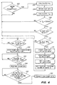
- FIG. 4 there is shown a flow diagram for the process logic used in batch transitioning between MPLs 10, 12.
- This logic diagram describes the start of the transition sequence and the mid-transition adjustment.
- the actual ramp rate will change depending on the actual coating apparatus conditions.
- computer 29 must first be informed whether the next operation between MPLs 10, 12 is a transition as opposed to a swing. This requires operator input in the form of, for example, a switch which the operator can set to swing or transition. If the answer is yes, per function box 102 the computer calculates the transition start weight (W s ). If the answer is no then logic recycles back to decision box 100 and this recycling continues until the answer is yes.
- W s transition start weight
- the weight of the contents of the old MPL 10, 12 is measured per function box 104 and the transition start time (T st ) is calculated per function box 106.
- T st transition start time
- the computer determines if the transition start time is less than 30 minutes. If the answer is no the logic again recycles back to decision box 100. If the answer is yes the computer asks if the new MPL 10, 12 is ready to begin a transition operation as indicated by decision box 110. If the answer is no then preferably an alarm is sounded to notify the operator to prepare the new MPL 10, 12. Per decision box 112, the computer then determines if the weight of the contents of the old MPL 10, 12 is less than the transition start weight (W s ).
- Pumps 36, 38 are then controlled (per function box 120) so that flow from the old MPL 10, 12 ramps down at a rate percent per minute (R) and the flow from the new MPL 10, 12 ramps up at the same rate (R).
- the computer determines when the flow ratio from the old MPL 10, 12 is less than 30% of the total flow as indicated by decision box 122. If the answer is no then logic continues to ask this question until the answer is yes.
- decision box 122 is yes then, per function box 124, ramping of the flow rate from pumps 36, 38 is halted with 100% flow continued at the then current flow rate ratio. The remaining solid within the old MPL 10, 12 are melted at this time.
- the computer determines whether the volume in sump 26 is less than the ramping restart volume (V r ) as indicated by decision box 126. If the answer is no then the flow logic continues to ask this question until the answer is yes. If the answer is yes then ramping of the flow rates from pumps 36, 38 is restarted at the same ramping rate (R) as indicated by function box 128. The computer then determines (per decision box 130) if the flow ratio from the old MPL 10, 12 is less than 5%, or if the volume in sump 26 is less than one liter. If the answer to either of these questions is no then the flow logic continues to ask this question until the answer is yes.
- the transition is completed. Flow from the old MPL 10, 12 is at zero and flow from the new MPL 10, 12 is at 100%.
- the following example shows the calculation of the weight of material in the exhausted MPL 10, 12 when the transition operation from batch to batch should begin. This is the transition start weight (W s ), the example also shows the calculation for the time until the transition operation should begin. This is the transition start time (T st ).
- the example further shows the calculation for the current ramp rate of change (R) and the second critical volume in the sump 26 at which the transition should restart. This second critical volume is referred to as the ramping restart volume (V r ).
- the current flow rate ratio (r) of the old MPL begins at 95% and is adjusted downward by each iterative calculation of the the current ramp rate of change (R).
- the equation given below allows for two coating apparatus (C 1 and C 2 ) to be supplied by the batch blending method of the present invention, the example assumes a single coating apparatus is being supplied. Thus, the values inserted into the equations for the second coating machine are zero.
- the example further assumes an aim flow rate (F aim ) to the coating apparatus of 2.0 l/min., an actual flow rate (F act ) of 0.1 l/min to the coating apparatus, a transition time (T) of 180 min., and a specific gravity (S g ) of the coating liquid of 1.1 kg/l.
- the transition time will be about 180 minutes and the start weight for each MPL is in the range of from about 500 kg to about 600 kg.
- ramp rate of change is described herein as being continuous, it should be appreciated that the ramp rate is a function of the frequency at which computer makes adjustments to the flow ratio. This calculation can be made, for example, once every second, once every 10 seconds, or once every minute. As such "continuous ramping" as used herein is intended to include a series of step changes to the ramp rate.
Landscapes
- Chemical & Material Sciences (AREA)
- Chemical Kinetics & Catalysis (AREA)
- Engineering & Computer Science (AREA)
- Materials Engineering (AREA)
- Physics & Mathematics (AREA)
- General Physics & Mathematics (AREA)
- Application Of Or Painting With Fluid Materials (AREA)
- Pipeline Systems (AREA)
- Feeding, Discharge, Calcimining, Fusing, And Gas-Generation Devices (AREA)
Claims (4)
- Verfahren zum Mischen von Chargen geschmolzener Feststoffe, mit folgenden Schritten:a) Schmelzen einer ersten Charge eines Feststoffs von bekannter Menge über einen Zeitraum, wobei die erste Charge in einer ersten Verflüssigungsvorrichtung enthalten ist;b) Pumpen des geschmolzenen Feststoffs der ersten Charge in einen Auffangbehälter mit vorbestimmter Förderleistung, bis in der ersten Verflüssigungsvorrichtung eine vorbestimmte Restmenge der ersten Charge zurückbleibt;c) Reduzieren der vorbestimmten Förderleistung, mit welcher die erste Charge gepumpt wird, um einen vorbestimmten Betrag;d) Anfangen mit dem Schmelzen einer zweiten Charge des Feststoffs von bekannter Menge, wobei die zweite Charge in einer zweiten Verflüssigungsvorrichtung enthalten ist;e) Pumpen des geschmolzenen Materials der zweiten Charge in den Auffangbehälter mit einer der vorbestimmten Förderleistung entsprechenden Förderleistung, so dass eine kombinierte Förderleistung entsteht, welche der vorbestimmten Förderleistung entspricht;f) Erhöhen der Pumpleistung aus der zweiten Verflüssigungsvorrichtung bei gleichzeitiger Reduzierung der Pumpleistung aus der ersten Verflüssigungsvorrichtung; undg) Aufrechterhalten der kombinierten Förderleistung während des Erhöhungsschritts, damit sie der vorbestimmten Förderleistung entspricht.
- Verfahren nach Anspruch 1, gekennzeichnet durch folgende Schritte:a) Fortführen der Erhöhungsschritte, bis die erste Charge des Feststoffs in der ersten Verflüssigungsvorrichtung im wesentlichen erschöpft ist;b) Einstellen der Tätigkeit, geschmolzenes Material aus der ersten Verflüssigungsvorrichtung zu pumpen;c) Pumpen des geschmolzenen Feststoffs aus der zweiten Verflüssigungsvorrichtung in den Auffangbehälter mit der vorbestimmten Förderleistung.
- Verfahren nach Anspruch 2, gekennzeichnet durch folgende Schritte:a) Aufrechterhalten der Pumpleistung aus der ersten und zweiten Verflüssigungsvorrichtung, sobald ein vorbestimmtes Verhältnis erreicht worden ist;b) Verflüssigen des restlichen Feststoffs der ersten Charge; undc) Fortführen der Erhöhung der Pumpleistung aus der zweiten Verflüssigungsvorrichtung bei gleichzeitigem Fortsetzen der Senkung der Pumpleistung aus der ersten Verflüssigungsvorrichtung, bis die erste Verflüssigungsvorrichtung im wesentlichen leer ist.
- Vorrichtung zum Mischen von Chargen geschmolzener Feststoffe, mit folgenden Komponenten:a) einer ersten Verflüssigungsvorrichtung zum Schmelzen von Feststoffen;b) einer zweiten Verflüssigungsvorrichtung zum Schmelzen von Feststoffen;c) einer ersten Pumpe zum Pumpen von geschmolzenem Material aus der ersten Verflüssigungsvorrichtung mit einer gewünschten Förderleistung in einen Auffangbehälter;d) einer zweiten Pumpe zum Pumpen von geschmolzenem Material aus der zweiten Verflüssigungsvorrichtung in den Auffangbehälter;e) einer Einrichtung zum Senken der Förderleistung der ersten Pumpe in Abhängigkeit vom in der ersten Verflüssigungsvorrichtung verbliebenen, vorbestimmten Rest der ersten Charge;f) einer Einrichtung zum Erhöhen der Förderleistung der zweiten Pumpe in Abhängigkeit vom in der ersten Verflüssigungsvorrichtung verbliebenen, vorbestimmten Rest der ersten Charge;g) einer Einrichtung zum Steuern des Verhältnisses zwischen der Förderleistung der ersten Pumpe und der Förderleistung der zweiten Pumpe; undh) einer Einrichtung zum Aufrechterhalten einer konstanten, kombinierten Förderleistung aus der Förderleistung der ersten Pumpe und der Förderleistung der zweiten Pumpe.
Applications Claiming Priority (2)
| Application Number | Priority Date | Filing Date | Title |
|---|---|---|---|
| US924687 | 1992-07-30 | ||
| US08/924,687 US6056431A (en) | 1997-09-05 | 1997-09-05 | Modified passive liquefier batch transition process |
Publications (3)
| Publication Number | Publication Date |
|---|---|
| EP0901039A2 EP0901039A2 (de) | 1999-03-10 |
| EP0901039A3 EP0901039A3 (de) | 2000-03-29 |
| EP0901039B1 true EP0901039B1 (de) | 2004-06-23 |
Family
ID=25450554
Family Applications (1)
| Application Number | Title | Priority Date | Filing Date |
|---|---|---|---|
| EP98202806A Expired - Lifetime EP0901039B1 (de) | 1997-09-05 | 1998-08-21 | Verfahren zum Übergang von einer Emulsions-Charge zur anderen unter Verwendung eines passiven Verflüssigungsapparates |
Country Status (4)
| Country | Link |
|---|---|
| US (1) | US6056431A (de) |
| EP (1) | EP0901039B1 (de) |
| JP (1) | JPH11151435A (de) |
| DE (1) | DE69824674T2 (de) |
Families Citing this family (3)
| Publication number | Priority date | Publication date | Assignee | Title |
|---|---|---|---|---|
| US6558554B1 (en) | 2001-12-12 | 2003-05-06 | Eastman Kodak Company | Method for switching filters on-line without bubbles and with zero liquid waste |
| US6732017B2 (en) * | 2002-02-15 | 2004-05-04 | Lam Research Corp. | System and method for point of use delivery, control and mixing chemical and slurry for CMP/cleaning system |
| CN112304586B (zh) * | 2020-10-19 | 2023-03-14 | 中国科学院合肥物质科学研究院 | 一种east偏滤器阻力特性测试及吹扫效率试验系统及方法 |
Family Cites Families (36)
| Publication number | Priority date | Publication date | Assignee | Title |
|---|---|---|---|---|
| US328714A (en) * | 1885-10-20 | Apparatus for remelting soap | ||
| US180688A (en) * | 1876-08-01 | Improvement in soap-remelters | ||
| US2253176A (en) * | 1938-08-09 | 1941-08-19 | Du Pont | Method and apparatus for production of structures |
| NL58719C (de) * | 1939-03-28 | |||
| US2683073A (en) * | 1951-08-22 | 1954-07-06 | Du Pont | Process for preventing nylon gel formation |
| US2872296A (en) * | 1957-03-26 | 1959-02-03 | Ralph B Lemon | Continuous dissolver extractor for processing metal |
| US3042481A (en) * | 1960-08-05 | 1962-07-03 | Monsanto Chemicals | Melt-spinning method |
| US3032635A (en) * | 1960-10-03 | 1962-05-01 | August L Kraft | Heater and utilization system for converting small quantities of fusible solids |
| US3178067A (en) * | 1963-03-19 | 1965-04-13 | Anderson Clayton & Co | Apparatus for the conversion of a solid material to a liquid state and metering thereof |
| JPS5031447B1 (de) * | 1971-02-08 | 1975-10-11 | ||
| US3810778A (en) * | 1971-05-03 | 1974-05-14 | Polaroid Corp | Method for production of a photographic film |
| US4018426A (en) * | 1976-03-17 | 1977-04-19 | Petrolite Corporation | System for producing emulsions |
| DE2836545C2 (de) * | 1978-08-21 | 1984-11-08 | Fa. Henning J. Claassen, 2120 Lüneburg | Gerät zum Verflüssigen von Schmelzmassen, insbesondere Schmelzklebestoffen |
| US4307705A (en) * | 1978-12-04 | 1981-12-29 | Marvin Douglas | Direct flame heated gridwork |
| JPS55159928A (en) * | 1979-06-01 | 1980-12-12 | Fuji Photo Film Co Ltd | Melting method and device for gel-like material |
| US4272824A (en) * | 1979-08-17 | 1981-06-09 | Pennant Products, Inc. | Batch product preparation |
| DE3033000A1 (de) * | 1980-09-02 | 1982-04-15 | Agfa-Gevaert Ag, 5090 Leverkusen | Verfahren zur herstellung von dispersionen und fotografische materialien |
| US4427298A (en) * | 1982-09-30 | 1984-01-24 | E. I. Du Pont De Nemours And Company | Method and system for accurately providing fluid blends |
| JPS60161724A (ja) * | 1984-02-01 | 1985-08-23 | Toshiba Corp | 混合制御装置 |
| US4639205A (en) * | 1984-07-31 | 1987-01-27 | E. I. Du Pont De Nemours And Company | Pump shaft stirrer for grid melter |
| US4771920A (en) * | 1985-10-29 | 1988-09-20 | Nordson Corporation | Thermoplastic grid melter |
| DE3640980C1 (de) * | 1986-12-01 | 1988-05-19 | Meinz Hans Willi | Vorrichtung zum Steuern und Messen eines vorwaehlbaren Hydraulikstromes |
| FR2626088B1 (fr) * | 1988-01-18 | 1990-06-01 | Kodak Pathe | Procede d'obtention d'une composition de couchage photographique |
| US4844927A (en) * | 1988-06-20 | 1989-07-04 | National By-Products, Inc. | Storage tank assembly for bulk fat and method for using same |
| US4976546A (en) * | 1989-05-12 | 1990-12-11 | Beattie Lewis J | Two component fluid mixing and dispensing system |
| US5100699A (en) * | 1989-08-24 | 1992-03-31 | Minnesota Mining And Manufacturing Company | Method and apparatus for precision pumping, ratioing, and dispensing of work fluid(s) |
| US5098194A (en) * | 1990-06-27 | 1992-03-24 | Union Carbide Chemicals & Plastics Technology Corporation | Semi-continuous method and apparatus for forming a heated and pressurized mixture of fluids in a predetermined proportion |
| US5171089A (en) * | 1990-06-27 | 1992-12-15 | Union Carbide Chemicals & Plastics Technology Corporation | Semi-continuous method and apparatus for forming a heated and pressurized mixture of fluids in a predetermined proportion |
| US5045445A (en) * | 1990-06-29 | 1991-09-03 | E. I. Du Pont De Nemours And Company | Continuous in-line preparation of photographic gelatin solutions |
| US5156298A (en) * | 1991-04-11 | 1992-10-20 | Eastman Kodak Company | Method and apparatus for detecting a limit of the usable portion of a batch of fluent material flowing in a conduit |
| US5523537A (en) * | 1991-12-31 | 1996-06-04 | Eastman Kodak Company | Passive liquifier |
| US5340210A (en) * | 1992-02-25 | 1994-08-23 | Nalco Chemical Company | Apparatus for blending chemicals with a reversible multi-speed pump |
| US5374120A (en) * | 1993-12-06 | 1994-12-20 | Eastman Kodak Company | Modified passive liquid in-line segmented blender |
| US5415232A (en) * | 1994-01-21 | 1995-05-16 | Baker Hughes Incorporated | Method and apparatus for ramping of stimulation chemical concentrations for treatment of subterranean formations |
| US5814790A (en) * | 1995-10-04 | 1998-09-29 | Nordson Corporation | Apparatus and method for liquifying thermoplastic material |
| DE19625208A1 (de) * | 1996-06-25 | 1998-01-02 | Micafil Vakuumtechnik Ag | Vorrichtung zum Mischen und Entgasen einer fließfähigen Masse |
-
1997
- 1997-09-05 US US08/924,687 patent/US6056431A/en not_active Expired - Lifetime
-
1998
- 1998-08-21 EP EP98202806A patent/EP0901039B1/de not_active Expired - Lifetime
- 1998-08-21 DE DE69824674T patent/DE69824674T2/de not_active Expired - Lifetime
- 1998-09-07 JP JP10252371A patent/JPH11151435A/ja active Pending
Also Published As
| Publication number | Publication date |
|---|---|
| DE69824674T2 (de) | 2005-07-21 |
| EP0901039A2 (de) | 1999-03-10 |
| JPH11151435A (ja) | 1999-06-08 |
| EP0901039A3 (de) | 2000-03-29 |
| DE69824674D1 (de) | 2004-07-29 |
| US6056431A (en) | 2000-05-02 |
Similar Documents
| Publication | Publication Date | Title |
|---|---|---|
| KR100446157B1 (ko) | 압력 탱크로부터 유체를 배분하기 위한 방법 및 장치 | |
| EP0494453B1 (de) | Verfahren und Vorrichtung zur Messung des Materialflusses in einer Zweikomponenten-Abgabevorrichtung | |
| US8172545B2 (en) | Method for controlling ground meat flow rates | |
| JPS63171567A (ja) | 血液成分分離装置 | |
| US6056431A (en) | Modified passive liquefier batch transition process | |
| US3810778A (en) | Method for production of a photographic film | |
| SE467647B (sv) | Anlaeggning foer framstaellning av vaetskeformiga limkompositioner | |
| AU649576B2 (en) | Passive liquifier | |
| US4218145A (en) | Liquid asphalt weigh out system | |
| US4958934A (en) | Method and apparatus for continuous melting of gelled substance | |
| US4026668A (en) | Control apparatus for silver halide emulsion making | |
| CN112551866A (zh) | Tft-lcd铂金通道流量控制方法、装置及存储介质 | |
| JPS5950967B2 (ja) | 写真材料の製造方法 | |
| JPS60261570A (ja) | 吐出される熱溶融形熱可塑性接着剤フオームのガス含有量を制御する方法及びその装置 | |
| US6416582B2 (en) | Liquid usage detector for a coating apparatus | |
| JP3403649B2 (ja) | 含気生地の製造方法および装置 | |
| CN119345981A (zh) | 一种非均相物混合控制方法及系统 | |
| US6640996B2 (en) | Method and apparatus for online switching between supply vessels | |
| JPH11164645A (ja) | 含気生地の製造方法および装置 | |
| JP3040313B2 (ja) | 低濃度調整装置 | |
| CN117244459A (zh) | 一种基于反馈调节的发泡剂溶液在线配制添加方法 | |
| JPH1183604A (ja) | 粘性流体の供給方法及びその装置 | |
| JP2002302263A (ja) | ホッパ内の石炭量制御方法 | |
| JPH07124460A (ja) | 原液連続流量制御装置 | |
| JPH05285436A (ja) | ダイコーティング用塗料供給装置 |
Legal Events
| Date | Code | Title | Description |
|---|---|---|---|
| PUAI | Public reference made under article 153(3) epc to a published international application that has entered the european phase |
Free format text: ORIGINAL CODE: 0009012 |
|
| AK | Designated contracting states |
Kind code of ref document: A2 Designated state(s): DE FR GB |
|
| AX | Request for extension of the european patent |
Free format text: AL;LT;LV;MK;RO;SI |
|
| PUAL | Search report despatched |
Free format text: ORIGINAL CODE: 0009013 |
|
| AK | Designated contracting states |
Kind code of ref document: A3 Designated state(s): AT BE CH CY DE DK ES FI FR GB GR IE IT LI LU MC NL PT SE |
|
| AX | Request for extension of the european patent |
Free format text: AL;LT;LV;MK;RO;SI |
|
| RIC1 | Information provided on ipc code assigned before grant |
Free format text: 7G 03C 1/025 A, 7B 29B 13/02 B, 7B 01F 15/04 B |
|
| 17P | Request for examination filed |
Effective date: 20000904 |
|
| AKX | Designation fees paid |
Free format text: DE FR GB |
|
| 17Q | First examination report despatched |
Effective date: 20010116 |
|
| GRAP | Despatch of communication of intention to grant a patent |
Free format text: ORIGINAL CODE: EPIDOSNIGR1 |
|
| GRAS | Grant fee paid |
Free format text: ORIGINAL CODE: EPIDOSNIGR3 |
|
| GRAA | (expected) grant |
Free format text: ORIGINAL CODE: 0009210 |
|
| AK | Designated contracting states |
Kind code of ref document: B1 Designated state(s): DE FR GB |
|
| REG | Reference to a national code |
Ref country code: GB Ref legal event code: FG4D |
|
| PGFP | Annual fee paid to national office [announced via postgrant information from national office to epo] |
Ref country code: GB Payment date: 20040707 Year of fee payment: 7 |
|
| REF | Corresponds to: |
Ref document number: 69824674 Country of ref document: DE Date of ref document: 20040729 Kind code of ref document: P |
|
| PGFP | Annual fee paid to national office [announced via postgrant information from national office to epo] |
Ref country code: FR Payment date: 20040804 Year of fee payment: 7 |
|
| ET | Fr: translation filed | ||
| PLBE | No opposition filed within time limit |
Free format text: ORIGINAL CODE: 0009261 |
|
| STAA | Information on the status of an ep patent application or granted ep patent |
Free format text: STATUS: NO OPPOSITION FILED WITHIN TIME LIMIT |
|
| 26N | No opposition filed |
Effective date: 20050324 |
|
| PG25 | Lapsed in a contracting state [announced via postgrant information from national office to epo] |
Ref country code: GB Free format text: LAPSE BECAUSE OF NON-PAYMENT OF DUE FEES Effective date: 20050821 |
|
| PGFP | Annual fee paid to national office [announced via postgrant information from national office to epo] |
Ref country code: DE Payment date: 20050831 Year of fee payment: 8 |
|
| PG25 | Lapsed in a contracting state [announced via postgrant information from national office to epo] |
Ref country code: DE Free format text: LAPSE BECAUSE OF THE APPLICANT RENOUNCES Effective date: 20060221 |
|
| GBPC | Gb: european patent ceased through non-payment of renewal fee |
Effective date: 20050821 |
|
| PG25 | Lapsed in a contracting state [announced via postgrant information from national office to epo] |
Ref country code: FR Free format text: LAPSE BECAUSE OF NON-PAYMENT OF DUE FEES Effective date: 20060428 |
|
| REG | Reference to a national code |
Ref country code: FR Ref legal event code: ST Effective date: 20060428 |