EP0901047B1 - Bilderzeugungsgerät - Google Patents
Bilderzeugungsgerät Download PDFInfo
- Publication number
- EP0901047B1 EP0901047B1 EP98116865A EP98116865A EP0901047B1 EP 0901047 B1 EP0901047 B1 EP 0901047B1 EP 98116865 A EP98116865 A EP 98116865A EP 98116865 A EP98116865 A EP 98116865A EP 0901047 B1 EP0901047 B1 EP 0901047B1
- Authority
- EP
- European Patent Office
- Prior art keywords
- charging
- toner
- image
- bearing member
- image bearing
- Prior art date
- Legal status (The legal status is an assumption and is not a legal conclusion. Google has not performed a legal analysis and makes no representation as to the accuracy of the status listed.)
- Expired - Lifetime
Links
- 238000012546 transfer Methods 0.000 claims description 41
- 239000006249 magnetic particle Substances 0.000 claims description 33
- 230000005291 magnetic effect Effects 0.000 claims description 22
- 239000000463 material Substances 0.000 claims description 22
- 239000010410 layer Substances 0.000 claims description 21
- 238000002347 injection Methods 0.000 claims description 12
- 239000007924 injection Substances 0.000 claims description 12
- 230000000694 effects Effects 0.000 claims description 7
- 238000011144 upstream manufacturing Methods 0.000 claims description 7
- 238000004140 cleaning Methods 0.000 claims description 5
- 230000007423 decrease Effects 0.000 claims description 5
- 230000007420 reactivation Effects 0.000 claims description 3
- 239000000835 fiber Substances 0.000 claims description 2
- 239000002344 surface layer Substances 0.000 claims 2
- 230000015572 biosynthetic process Effects 0.000 description 8
- 238000000151 deposition Methods 0.000 description 6
- 238000011161 development Methods 0.000 description 6
- 238000004519 manufacturing process Methods 0.000 description 6
- 238000000034 method Methods 0.000 description 6
- 239000002245 particle Substances 0.000 description 6
- 230000002093 peripheral effect Effects 0.000 description 6
- 230000008021 deposition Effects 0.000 description 5
- 230000006870 function Effects 0.000 description 5
- XAGFODPZIPBFFR-UHFFFAOYSA-N aluminium Chemical compound [Al] XAGFODPZIPBFFR-UHFFFAOYSA-N 0.000 description 4
- 229910052782 aluminium Inorganic materials 0.000 description 4
- 239000011347 resin Substances 0.000 description 4
- 229920005989 resin Polymers 0.000 description 4
- 230000008859 change Effects 0.000 description 3
- 238000007599 discharging Methods 0.000 description 3
- 230000005684 electric field Effects 0.000 description 3
- 230000008569 process Effects 0.000 description 3
- 230000001105 regulatory effect Effects 0.000 description 3
- 230000000630 rising effect Effects 0.000 description 3
- CBENFWSGALASAD-UHFFFAOYSA-N Ozone Chemical compound [O-][O+]=O CBENFWSGALASAD-UHFFFAOYSA-N 0.000 description 2
- 230000008901 benefit Effects 0.000 description 2
- 239000003990 capacitor Substances 0.000 description 2
- 230000005294 ferromagnetic effect Effects 0.000 description 2
- 230000006872 improvement Effects 0.000 description 2
- 230000007774 longterm Effects 0.000 description 2
- 238000005259 measurement Methods 0.000 description 2
- 239000004065 semiconductor Substances 0.000 description 2
- 229910001220 stainless steel Inorganic materials 0.000 description 2
- 239000010935 stainless steel Substances 0.000 description 2
- 239000004925 Acrylic resin Substances 0.000 description 1
- 229920000178 Acrylic resin Polymers 0.000 description 1
- OKTJSMMVPCPJKN-UHFFFAOYSA-N Carbon Chemical compound [C] OKTJSMMVPCPJKN-UHFFFAOYSA-N 0.000 description 1
- 239000004677 Nylon Substances 0.000 description 1
- 230000004913 activation Effects 0.000 description 1
- 229910052787 antimony Inorganic materials 0.000 description 1
- WATWJIUSRGPENY-UHFFFAOYSA-N antimony atom Chemical compound [Sb] WATWJIUSRGPENY-UHFFFAOYSA-N 0.000 description 1
- 238000013459 approach Methods 0.000 description 1
- 230000002238 attenuated effect Effects 0.000 description 1
- 239000011230 binding agent Substances 0.000 description 1
- 229910052799 carbon Inorganic materials 0.000 description 1
- 238000006243 chemical reaction Methods 0.000 description 1
- 239000011248 coating agent Substances 0.000 description 1
- 239000011247 coating layer Substances 0.000 description 1
- 238000000576 coating method Methods 0.000 description 1
- 239000003086 colorant Substances 0.000 description 1
- 238000011109 contamination Methods 0.000 description 1
- 230000001276 controlling effect Effects 0.000 description 1
- 230000009849 deactivation Effects 0.000 description 1
- 230000003247 decreasing effect Effects 0.000 description 1
- 230000007547 defect Effects 0.000 description 1
- 230000001419 dependent effect Effects 0.000 description 1
- 230000006866 deterioration Effects 0.000 description 1
- 125000000664 diazo group Chemical group [N-]=[N+]=[*] 0.000 description 1
- 238000009826 distribution Methods 0.000 description 1
- 238000002474 experimental method Methods 0.000 description 1
- 230000035553 feeding performance Effects 0.000 description 1
- 239000000945 filler Substances 0.000 description 1
- 150000007857 hydrazones Chemical class 0.000 description 1
- 238000004898 kneading Methods 0.000 description 1
- 239000000696 magnetic material Substances 0.000 description 1
- 125000004184 methoxymethyl group Chemical group [H]C([H])([H])OC([H])([H])* 0.000 description 1
- 239000000203 mixture Substances 0.000 description 1
- 238000012986 modification Methods 0.000 description 1
- 230000004048 modification Effects 0.000 description 1
- 229920001778 nylon Polymers 0.000 description 1
- 239000000049 pigment Substances 0.000 description 1
- 239000000088 plastic resin Substances 0.000 description 1
- 229920006122 polyamide resin Polymers 0.000 description 1
- 239000004431 polycarbonate resin Substances 0.000 description 1
- 229920005668 polycarbonate resin Polymers 0.000 description 1
- 238000006116 polymerization reaction Methods 0.000 description 1
- 239000000843 powder Substances 0.000 description 1
- 230000002265 prevention Effects 0.000 description 1
- 230000004044 response Effects 0.000 description 1
- 238000004381 surface treatment Methods 0.000 description 1
- 239000004094 surface-active agent Substances 0.000 description 1
- XOLBLPGZBRYERU-UHFFFAOYSA-N tin dioxide Chemical compound O=[Sn]=O XOLBLPGZBRYERU-UHFFFAOYSA-N 0.000 description 1
- 229910001887 tin oxide Inorganic materials 0.000 description 1
- 239000011882 ultra-fine particle Substances 0.000 description 1
- XLYOFNOQVPJJNP-UHFFFAOYSA-N water Substances O XLYOFNOQVPJJNP-UHFFFAOYSA-N 0.000 description 1
- 229910000859 α-Fe Inorganic materials 0.000 description 1
Images

Classifications
-
- G—PHYSICS
- G03—PHOTOGRAPHY; CINEMATOGRAPHY; ANALOGOUS TECHNIQUES USING WAVES OTHER THAN OPTICAL WAVES; ELECTROGRAPHY; HOLOGRAPHY
- G03G—ELECTROGRAPHY; ELECTROPHOTOGRAPHY; MAGNETOGRAPHY
- G03G15/00—Apparatus for electrographic processes using a charge pattern
- G03G15/02—Apparatus for electrographic processes using a charge pattern for laying down a uniform charge, e.g. for sensitising; Corona discharge devices
- G03G15/0208—Apparatus for electrographic processes using a charge pattern for laying down a uniform charge, e.g. for sensitising; Corona discharge devices by contact, friction or induction, e.g. liquid charging apparatus
- G03G15/0241—Apparatus for electrographic processes using a charge pattern for laying down a uniform charge, e.g. for sensitising; Corona discharge devices by contact, friction or induction, e.g. liquid charging apparatus by bringing charging powder particles into contact with the member to be charged, e.g. by means of a magnetic brush
-
- G—PHYSICS
- G03—PHOTOGRAPHY; CINEMATOGRAPHY; ANALOGOUS TECHNIQUES USING WAVES OTHER THAN OPTICAL WAVES; ELECTROGRAPHY; HOLOGRAPHY
- G03G—ELECTROGRAPHY; ELECTROPHOTOGRAPHY; MAGNETOGRAPHY
- G03G2215/00—Apparatus for electrophotographic processes
- G03G2215/02—Arrangements for laying down a uniform charge
- G03G2215/021—Arrangements for laying down a uniform charge by contact, friction or induction
- G03G2215/022—Arrangements for laying down a uniform charge by contact, friction or induction using a magnetic brush
Definitions
- the present invention relates to an image forming apparatus comprising a charging member contactable to an image bearing member to charge the image bearing member such as a photosensitive member or a dielectric member.
- a corona charger is widely used as a charging means for the image bearing member such as an electrophotographic photosensitive member or an electrostatic recording dielectric member.
- a contact charging device wherein a charging member applied with a voltage is contacted to a member to be charged to charge it, has been put into practice, and it has advantages of low ozone production, low electric power or the like.
- a roller type charging device using a dielectric roller is preferred because of its charging stability.
- the charging is effected by the discharge from the charging member to the member to be charged, and therefore, the surface potential of the photosensitive member varies depending on the change of the ambience and the variation of the electric resistances of-the charging roller and the change.
- the contact charging member having an electroconductivity As regards the contact charging member having an electroconductivity, charging furbrush, charging magnetic brush or the like is usable. But, when the elasticity of the charging furbrush is deteriorated due to the long term use or long term non-use, the charging property is worsened. The charging magnetic brush does not involve such a problem so that stabilized charging continues..
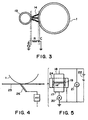
- the injection charging using the charging magnetic brush is understood as being equivalent to the series circuit of the resistance R and the capacitor C as shown in Figure 3.
- the capacitor C is being charged for the time period in which a certain point of the photosensitive member surface is in contact to the magnetic brush(charging nip multiplied by a peripheral speed of the photosensitive member), so that surface potential of the photosensitive member becomes substantially equal to the applied voltage.
- the toner is collected by a developing device without using a cleaner after the transfer and before the charging(cleanerless type)
- the toner is mixed in the magnetic brush, and the electric resistance thereof gradually increases.
- the charge does not sufficiently move during passing through the charging nip, and the surface potential of the photosensitive member after the passing of the charging nip is lower than the applied voltage(the potential difference between the surface potential of the photosensitive member and the applied voltage is &LD&V).
- the decrease of the photosensitive member potential results in a toner deposition on the non-image portion in the development(so-called fog) without means for detecting the surface potential and for controlling the developing bias.
- &LD&V is large, the magnetic particle of the magnetic brush is deposited on the photosensitive member surface, and it is discharged from the charger with the result of improper charging.
- the introduced toner is ejected to the photosensitive member surface from the magnetic brush by the electric field generated by the potential difference &LD&V between the applied voltage and the surface potential of the photosensitive member.
- the difference &LD&V increases with the increase of the electric resistance of the magnetic brush i.e. Amount of introduced toner in the magnetic brush), and toner amount ejected increases with the increase of &LD&V, and therefore, if the amount of the untransferred toner does not varies significantly, the amount of introduced toner in the magnetic brush is substantially constant so that charged potential is stabilized.
- &LD&V is dependent on the bias for the charging and that it is larger in a bias using DC only than in a bias including an AC component.
- EP-A-766146 discloses use of such nature by which AC biased voltage is used during the image formation, and the bias of DC only is used when the toner is ejected, so that toner content in the charger is maintained low.
- the toner collected by the injection charging device is not limited to the untransferred toner described above.
- the untransferred toner image occurring at the resetting operation after an enforced stop of the apparatus due to sheet jam or power failure or the like, has to be collected by the injection charging device when a non-contact type transfer charger or contact type transfer roller is used.
- a transfer belt 25 is contacted to a photosensitive member 1 by an electroconductive brush or an electroconductive blade 26 to transfer the toner onto the transfer material carried on a belt 25, the electroconductive brush and/or the electroconductive blade 26 has to be separated until the same peripheral speeds are reached to prevent the damage of the photosensitive member 1 due to a peripheral speed difference upon the start of the rotations of the photosensitive member 1 and the transfer belt 25, and therefore, it is difficult to remove the toner by transferring the untransferred toner onto the transfer belt 25 upon the start and then removing the toner by belt cleaner.
- the movement of the photosensitive member immediately stops in response to deactivation of the main switch, and therefore, a large amount of the toner remains on the photosensitive member.
- the toner content in the magnetic brush abruptly increases, with the result of abrupt increase of &LD&V, and the abrupt lowering of the charged potential. Therefore, even if the toner is ejected from the charger using the toner discharging DC bias(DC only), the developing device cannot collect all of the ejected toner, and in addition, the fog is produced, and the fog toner is introduced again in the injection charging device. Then, the toner content in the magnetic brush is further increased. As a result, the &LD&V is further increased, and the fog toner amount increases.
- the resistance of the magnetic brush increases to such an extent with the result of deposition of the magnetic particles onto the photosensitive member.
- Figure 1 is a schematic illustration of an image forming apparatus according to an embodiment of the present invention.
- the image forming apparatus shown in Figure 1 is provided with a photosensitive drum 1 rotatable in a direction indicated by the arrow, and around the photosensitive drum 1 there are provided a charger 2, a transfer charger 3, a developing device 6 and a pre-exposure lamp 10, and above the photosensitive drum 1, a laser beam scanner(unshown) is distributed.
- the original reading apparatus including a photoelectric conversion element such as CCD outputs an image signal corresponding to monochromatic image information of an original, and a semiconductor laser contained in a laser beam scanner is controlled corresponding to an image signal to ejection a laser beam 5.
- An output signal from a computer can be printed.
- the photosensitive drum 1 is first uniformly charged to a negative polarity by a charger 2.
- the photosensitive drum 1 is rotated at a process speed(peripheral speed) of 110mm/sec in a direction indicated by the arrow(clockwise direction).
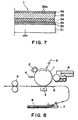
- the photosensitive drum 1 used in this embodiment is an OPC photosensitive member which is chargeable to the negative polarity, and as shown in Figure in Figure 7, it comprises an aluminum drum base member 31 having a diameter of 108mm, and first - fifth layers (function layers) thereon in this order.
- First layer is a primer layer 32, provided to uniform the defects of the aluminum drum base member(aluminum base) and to prevent production of moire due to reflection of the laser exposure. It is an electroconductive layer having a thickness of approx. 20 ⁇ m.
- the second layer is a positive-charge injection preventing layer 33 which functions to prevent cancellation of the negative charge of the surface of the photosensitive drum 1 by positive-charge injected from the aluminum base, and which is an intermediate resistance layer having a thickness of approx. 1 ⁇ m having a resistance adjusted to approx. 10 6 ⁇ cm by AMILAN (tradename of polyamide resin material, available from Toray Kabushiki Kaisha, Japan) resin material and methoxymethyl nylon.
- AMILAN tradename of polyamide resin material, available from Toray Kabushiki Kaisha, Japan
- the third layer is a charge generating layer 34 which is a layer having a thickness of approx.0.3 ⁇ m and comprising a resin material and disazo pigment dispersed therein and which generates couples of positive and negative charges upon reception of laser exposure.
- Fourth layer is a charge transfer layer 35 which is a P-type semiconductor comprising polycarbonate resin material and hydrazone dispersed therein. Therefore, the negative charge deposited on the surface of the photosensitive drum 1 is unable to pass through the fourth layer, and only the positive-charge generated in the charge generating layer can be moved to the surface of the photosensitive drum 1.
- the fifth layer is a charge injection layer 36 in the form of a coating layer which comprises light curing acrylic resin material(binder), antimony which is light transmissive electroconductive filler(electroconductive particle) 36a doped to decrease the resistance (electroconductivity), and 70 percent by weight, on the basis of the resin material, of ultra-fine particle of tin oxide having a particle size of 0.03 ⁇ m, dispersed therein, the layer having a thickness of approx. 3 ⁇ m.
- the charge injection layer preferably has such an electric resistance as has sufficient charging property and as does not form image flow, more particularly, 1x 10 10 -1x 10 14 ⁇ cm.
- the photosensitive drum 1 has a surface resistance of 1x 10 12 ⁇ cm.
- the collection property of the toner ejected from the injection charging device is improved by the use of two-component contact type developing system with a developer which is a mixture of high parting property spherical non-magnetic toner which is produced by polymerization method and with which the amount of untransferred toner is small and magnetic carrier.
- the development property in this embodiment is such that fog is produced if the difference between the charged potential and the DC component value of the developing bias is not less than 200V, and the developer carrier is deposited on the photosensitive drum 1 if it is not less than 350V, and therefore, the DC component value of the developing bias is -400V.
- a transfer material 8 is picked out from a sheet feeding cassette 7, and is fed to a transfer portion between the photosensitive drum 1 and a transfer charger(corona charger) 3 by a sheet feeding roller along a sheet feeding guide, and the toner image formed on the photosensitive drum 1 is transferred onto the transfer material 8 by operation of the transfer charger 3.
- the transfer charger shown in Figure 4 may be replaced with a combination of a charging roller or a transfer belt and an electroconductive brush, an electroconductive blade, an electroconductive roller press-contacted to a back side thereof (contact type transfer charger).
- the toner remaining on the surface of the photosensitive drum 1 without being transferred, is temporarily collected into the charger 2.
- the surface potential of the photosensitive drum 1 is discharged to approx. 0V immediately before the charging operation by a pre-exposure lamp 10 disposed between the transfer charger 3 and the charger 2.
- the photosensitive member, the charger, the developing device and the exposure device may be provided for yellow, magenta, cyan and black colors, and the toner image of the photosensitive members are sequentially transferred onto a transfer material carried on a transfer material holding member in the form of a belt or a drum, so that full-color image can be provided.
- the transfer material having the transferred toner image 8 is fed by a conveyer belt to a fixing device(heat roller fixing device) 9 where the toner image is fixed.
- the residual toner on the photosensitive member after image transfer is collected into the charger 2.
- the auxiliary member By the auxiliary member, the polarity of the residual toner is all made uniform to the positive charging, so that it becomes easy for the residual toner to be collected to the charger 2 supplied with a negative voltage.
- the toner once collected to the charger 2 is charged to the negative polarity by triboelectric charge with the magnetic particles of the charger 2, and is ejected to the photosensitive member 1 for the charger 2 by the potential difference &LD&V between the surface potential of the photosensitive member 1 charged by the charger 2 and the DC voltage applied to the charger 2.
- the developing device effects the developing operation and the cleaning operation simultaneously.
- the developing device 6 has a developer carrying member in the form of a sleeve.
- the developing sleeve is applied with a developing bias voltage between the dark portion potential and the light portion potential of the electrostatic latent image, and simultaneously with formation of an electric field for depositing the toner to the light portion of the photosensitive member from the developing sleeve, an electric field for collecting the toner to the developing sleeve from the dark portion of the photosensitive member, is formed.
- the developing device 6 effects the simultaneous developing operation and cleaning operation for cleaning the photosensitive member by removing the residual toner. If the residual toner amount on the photosensitive member is too large during the development, the toner is not sufficiently collected by the developing device with the result of fog toner remaining on the photosensitive member.
- FIG 2 is a sectional view of the charger 2.
- the container 11 comprises a sleeve 13 of non-magnetic material, a fixed magnet 12 therein, magnetic particles 14 for injecting the charge by contact to the photosensitive drum 1, a regulating blade 15 for coating the surface of the sleeve 13 with the magnetic particles 14 into a uniform thickness.
- the sleeve 12 of non-magnetic stainless steel is rotated at a peripheral speed of 165mm/sec in the same direction (clockwise direction) as the photosensitive drum 1. More particularly, the peripheral movement of the sleeve 12 and that of the drum 1 are opposite at the charging nip.
- the regulating blade 15 of non-magnetic stainless steel is disposed with a gap of 900pm from the surface of the sleeve 13.
- the stationary magnet in the sleeve 13 has a magnetic pole(main pole) of approx. 9 ⁇ 10 -2 T (900G) at a position of 10° from the closest position between the photosensitive drum 1 and the sleeve 13 toward an upstream side of the rotational direction of the photosensitive drum.
- the main pole is preferably disposed in the range between 20° upstream from the closest position and 10° downstream therefrom ( ⁇ in the Figure) with respect to the rotational direction of the photosensitive drum, and further preferably 15°- 0° upstream therefrom).
- the magnetic particles 14 are attracted to the main pole position, so that magnetic particles 14 tend to stagnate downstream of the charging nip with respect to the rotational direction of the photosensitive drum, and if it is more upstream, the feeding performance of the magnetic particles 14 after the charging nip is worsened, so that stagnation tends to occur.
- the magnetic pole is not provided in the charging nip, the confining force acting on the magnetic particles 14 toward the sleeve 13 is weak with the result of the tendency of the magnetic particles 14 being deposited onto the photosensitive drum 1.
- the charging nip is the region where the magnetic particle 14 is contacted to the photosensitive drum 1 during the charging.
- the charging bias in the form of an AC biased DC voltage is applied to the sleeve 13 and to the regulating blade 15.
- the DC voltage is the same as the required surface potential of the photosensitive drum 1 (-700V in this embodiment).
- the peak-to-peak voltage of the AC component (Vpp) is preferably 100V ⁇ Vpp ⁇ 2000V, and further preferably, 300V ⁇ Vpp ⁇ 1200V. If Vpp is lower than that, advantageous effects in the uniform charging property and the rising of the potential, is not so high, and if it is larger than that, the stagnation of the magnetic particles 14 and the deposition thereof on the photosensitive drum 1 are worsened.
- the frequency is preferably not less than 100Hz and not more than 5000Hz, more preferably not less than 500Hz and not more than 2000Hz. If it is lower than that, the deposition of the magnetic particles 14 on the photosensitive drum 1 is worsened, and the advantageous improvement of the rising of the potential and the uniform charging property is not so high. If it is larger than that, the advantageous improvement of the rising of the potential and the uniform charging property is not so high, either.
- the waveform of the AC component may be a rectangular wave, a triangular wave, a sin wave or the like.
- the magnetic particles 14 are produced by deoxidization process of sintered ferromagnetic member(ferrite), but this is not limiting, and they may be produced by kneading the ferromagnetic powder and another resin material and forming it to particles, or by mixing electroconductive carbon in them or by surface treatment of them to adjust the resistance
- the magnetic particle 14 has a function of injecting properly the charge to the trap level of the surface of the photosensitive drum 1 and a function of preventing the power supply failure to the charging member and the photosensitive drum 1 which may occur due to concentration of the charging current as a result of drawback such as a pin hole in the photosensitive drum 1.
- the resistance value of the charging member is preferably 1x 10 4 ⁇ -1x 10 9 ⁇ and further preferably 1x 10 4 ⁇ -1x 10 7 ⁇ . If the resistance value of the charging member is less than 1x 10 4 ⁇ , the pin hole leakage tends to occur, and if it exceeds 1x 10 9 ⁇ , charge is not good.
- the volume resistivity of the magnetic particle 14 is preferably 1x 10 4 ⁇ cm-1x 10 9 ⁇ cm, and further preferably 1x 10 4 ⁇ cm-1x 10 7 ⁇ cm.
- the volume resistivity of the magnetic particles 14 was measured using a cell A shown in Figure 5.
- the magnetic particles 14 are filled in the cell A, and electrodes 17 and 18 are contacted to the magnetic particles 14.
- a voltage is applied between the electrodes 17, 18, and the current is measured, and then the volume resistivity of the magnetic particles 14 are calculated.
- designated by 17 is a main electrode; 18 is an upper electrode; 19 is an insulative material; 20 is an ammeter; 21 is a voltmeter; 22 is a constant voltage means; and 24 is a guide ring.
- the average particle size and the peak of the magnetic particles 14 determined by the particle size distribution measurement are preferably in the range of 5-100 ⁇ m from the standpoint of prevention of deterioration of charging due to the contamination of the surfaces of the particles.
- the resistance value of the charging member used in this embodiment is 1x 10 6 ⁇ cm, and by the application of -700V as the DC component of the charging bias, the surface potential of the photosensitive drum 1 is charged to -700V.
- the experiments have been carried out as follows. Different amounts of the toner are mixed beforehand in the magnetic particles 14 of the charger. The amount of introduced toner in the magnetic particles 14 are measured when the toner is ejected to the drum from the charger for the case of the voltage having a DC component only applied to the sleeve 13 and for the case of the voltage having the AC and DC components applied thereto.
- Ct(g) of the magnetic particles is placed in a plastic resin material container having a weight Cp(g), and a magnet is contacted to the bottom side of the container to confine the magnetic particle to the bottom, and in this state, only the toner is washed out with water containing a surfactant.
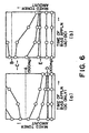
- Figure 6 (a) shows the results when the bias voltage having a DC component only is applied to the sleeve 13, wherein the amount of introduced toner and &LD&V hardly changes when the amount of introduced toner is not more than 100mg.
- the discharge toner amount limit D is understood as being 100mg.
- the initial amount of introduced toner is not less than 500mg, the amount of introduced toner increases with elapse of time.
- Figure 6, (b) shows the result when the sleeve 13 is supplied with a voltage in the form of an AC biased DC.
- the charging property is good, and the potential difference &LD&V between the surface potential of the photosensitive drum and the applied bias is small, so that ejection toner amount limit E and the toner content limit amount(in the Figure B) are larger than in the case of the DC bias voltage. Therefore, in Figure 6, when the amount of introduced toner is between A and B, the fog can be prevented, and the ejected toner can be collected by ejecting the toner by the AC plus DC voltage and then ejecting the toner by the DC voltage (without AC).
- the mixing limit amount of the toner which can be discharged can be reduced and the limit amount of the toner which can be discharged are reduced, by first applying to the sleeve the AC plus DC voltage and then DC bias(without thereafter AC) voltage.
- the maximum value of the untransferred toner amount on the photosensitive drum surface at the time of the sheet jam or power failure is approx. 120mg (the sheet jam between the registration roller and the transfer charger or the power failure when the sheet is therebetween).
- 500mg of the toner has been mixed in the charging magnetic particle beforehand, and the fog toner has been checked while changing the application period of the AC+DC bias voltage.
- Table 1 shows the results, wherein it will be understood that fog does not occur if the AC+DC bias voltage is applied for not less than 15sec, and thereafter, DC bias voltage (without AC) is applied.
- the charging sleeve 13 when the image forming apparatus is stopped due to the jam or power failure while the image formation is being carried out, the charging sleeve 13, after the main switch is activated again and before the stand-by state wherein the image forming operation is startable is established, is first supplied with an AC plus DC bias voltage to decrease the &LD&V, and then the DC without AC is applied to increase the &LD&V.
- the voltage source is shut off, and the operator opens the front door to clear the jam. Then, the operator close the door, and then the apparatus is restarted.
- the charging sleeve 13 is supplied with the AC plus DC voltage and then with DC (without AC) voltage between the activation of the power source and the stand-by state.
- the toner ejection can be carried out efficiently without occurrence of toner fog in the development and without sticking of the magnetic particles from the charger to the drum.
- the bias is switched from AC plus DC to DC only, but in this embodiment, the Vpp of the AC component of the applied bias voltage is gradually decreased to accomplish the toner discharge without fog.
- the peak-to-peak voltage of the AC component of the AC plus DC voltage applied to the charging sleeve 13 is attenuated gradually between the reactivation of the power source and the establishment of the stand-by state.
- Table 2 shows the relation between the attenuation speed of the peak-to-peak voltage Vpp (V/sec) and the fog production by the development.
- the attenuation speed of the Vpp of the AC component was changed to 20, 30, 40, 50, 60, 70V/sec.
- the latitude of the developing bias is larger in 20-50V/sec, and therefore, ejection does not produce the fog, but when it is higher than that, the latitude of the developing bias is smaller when the fog resulting from the ejected toner is prevented.
- an auxiliary member in the form of a fixed brush 4 is contacted to the photosensitive drum surface in place of the pre-exposure device between the transfer position and the charging position in Embodiment 1, and a voltage of the opposite polarity from the charge polarity of the charger is applied, by which the potential of the photosensitive drum is discharged to approx. 0V.
- a corona charger or the like is usable to discharge the photosensitive drum to approx. 0V, and the similar effects can be provided.
- the fixed brush 4 may be additionally supplied with an AC voltage in addition to the voltage, and it may be applied with a photosensitive drum voltage without DC voltage.
- the exposure device disposed between the transfer position and the charging position in Embodiment 1 is omitted, and the potential of the photosensitive drum is discharged to approx. 0V by the transfer charger supplied with the positive voltage during the toner discharging operation from the charger to the drum.
- the drum potential 0V By making the drum potential 0V, the toner discharge effect is improved as compared with the case of the negative drum potential.
- the apparatus when the apparatus stops without completion of the image formation, it is desirable to provide an adjusting apparatus for changing the time duration in which the superimposed voltage of the AC voltage and the DC voltage is applied to the charger after the reactivation of the electric power and before the establishment of the stand-by state, in accordance with the state of the stop of the apparatus. More particularly, the time duration of the superimposed voltage application is preferably longer if the amount of the untransferred toner on the image bearing member at the time of the stop of the apparatus is larger.
- the apparatus when the jam occurs at the position of the fixing device, the apparatus is preferably stopped immediately, so that amount of the untransferred toner is large.
- the toner image preferably is transferred onto the transfer material which is at the transfer position, and then the transfer material is discharged out, by which the amount of the untransferred toner can be reduced. Therefore, the time duration of the application of the superimposed voltage is changed in accordance with the jam occurrence position.
- time duration of the superimposed voltage application is made longer when the image ratio at the time of the stop of the apparatus without completion of the image formation, is larger, since then the cleaning efficiency is improved.
- the image ratio can be determined on the basis of the image signal(video signal).
Landscapes
- Physics & Mathematics (AREA)
- Engineering & Computer Science (AREA)
- Plasma & Fusion (AREA)
- General Physics & Mathematics (AREA)
- Electrostatic Charge, Transfer And Separation In Electrography (AREA)
Claims (10)
- Bilderzeugungsvorrichtung, umfassend:wobei die Ladeeinrichtung zum Sammeln und Zurückführen von auf dem das Bild tragenden Element verbleibendem Toner nach der Bildübertragung dient;ein ein Bild tragendes Element (1)eine Ladeeinrichtung (2) zum Aufladen und Kontaktieren des das Bild tragenden Elements;eine Steuereinrichtung zum Steuern einer an die Ladeeinrichtung angelegten Spannung;eine Bilderzeugungseinrichtung (5) zum Erzeugen eines elektrostatischen Bilds auf dem das Bild tragenden Element, das durch die Ladeeinrichtung aufgeladen wurde;eine Entwicklungseinrichtung (6) zum Entwickeln des elektrostatischen Bilds mittels Toner, wobei die Entwicklungseinrichtung in der Lage ist, das das Bild tragende Element zu reinigen, um Resttoner zu entfernen;eine Übertragungseinrichtung (3) zum Übertragen des Tonerbilds auf ein Übertragungsmaterial (8);
dadurch gekennzeichnet, daß
in dem Fall, in dem ein Bilderzeugungsvorgang der Bilderzeugungsvorrichtung ohne Beendigung des Bilderzeugungsvorgangs angehalten wird, die Steuereinrichtung dazu ausgelegt ist, daß bei einer Reaktivierung der Bilderzeugungsvorrichtung für eine Zeitdauer größer als 0 eine eine Wechselspannungskomponente und eine Gleichspannungskomponente umfassende Spannung angelegt wird, um den Toner mittels der Ladeeinrichtung zu sammeln, und nach der Zeitdauer die Steuereinrichtung die Wechselspannungskomponente beendet oder verringert, um den Toner von der Ladeeinrichtung zu dem das Bild tragenden Element zurückzuführen. - Vorrichtung nach Anspruch 1, bei der ein Bereich des das Bild tragenden Elements, welcher zu einem Bildbereich werden wird, an einer Ladeposition liegt, an der das das Bild tragende Element durch das Ladeelement geladen wird, wobei das Ladeelement mit der die Wechselspannungskomponente und die Gleichspannungskomponente umfassenden Spannung versorgt wird.
- Vorrichtung nach Anspruch 1, ferner umfassend ein Hilfselement (10; 4) zum Laden des Resttoners auf eine Polarität, die einer Ladepolarität des Ladeelements entgegengesetzt ist, wobei das Hilfselement in Bezug auf eine Bewegungsrichtung einer Oberfläche des das Bild tragenden Elements unterhalb einer Übertragungsposition, an der das Tonerbild auf ein Übertragungsmaterial übertragen wird, und oberhalb einer Position, an der das das Bild tragende Element durch das Ladelement geladen wird, angeordnet ist.
- Vorrichtung nach Anspruch 1, ferner umfassend eine Faserbürste (4), an die eine Spannung mit einer Polarität entgegengesetzt zu einer Ladepolarität des Ladeelements angelegt wird, wobei das Hilfselement in Bezug auf eine Bewegungsrichtung einer Oberfläche des das Bild tragenden Elements unterhalb einer Übertragungsposition, an der das Tonerbild auf ein Übertragungsmaterial übertragen wird, und oberhalb einer Position, an der das das Bild tragende Element durch das Ladeelement geladen wird, angeordnet ist.
- Vorrichtung nach Anspruch 1, bei der eine Zeitdauer, in welcher die die Wechselspannungskomponente und die Gleichspannungskomponente umfassende Spannung an das Ladeelement angelegt wird, in Übereinstimmung mit einer Stauauftrittsposition eines Übertragungsmaterials geändert wird, wenn die Vorrichtung den Betrieb anhält.
- Vorrichtung nach Anspruch 1, bei der eine Zeitdauer, in welcher die die Wechselspannungskomponente und die Gleichspannungskomponente umfassende Spannung an das Ladeelement angelegt wird, in Übereinstimmung mit einem Bildverhältnis geändert wird, wenn die Vorrichtung den Betrieb anhält.
- Vorrichtung nach Anspruch 1, bei der das Ladeelement mit einer magnetischen Bürste aus magnetischen Teilchen (14) versehen ist, die mit dem das Bild tragenden Element in Kontakt bringbar ist.
- Vorrichtung nach einem der Ansprüche 1 bis 7, bei der das Ladeelement eine Injektionsladung des das Bild tragenden Elements an einem Kontaktabschnitt zwischen dem Ladeelement und dem das Bild tragenden Element bewirkt.
- Vorrichtung nach einem der Ansprüche 1 bis 7, bei der das das Bild tragende Element mit einer Oberflächenschicht (36) mit einem Volumenwiderstand von 1x10¹⁰ bis 1x10¹⁴ Ωcm versehen ist.
- Vorrichtung nach Anspruch 9, bei der das das Bild tragende Element eine elektrophotograhisch photoempfindliche Schicht innerhalb der Oberflächenschicht aufweist.
Applications Claiming Priority (3)
| Application Number | Priority Date | Filing Date | Title |
|---|---|---|---|
| JP24133897 | 1997-09-05 | ||
| JP241338/97 | 1997-09-05 | ||
| JP24133897 | 1997-09-05 |
Publications (3)
| Publication Number | Publication Date |
|---|---|
| EP0901047A2 EP0901047A2 (de) | 1999-03-10 |
| EP0901047A3 EP0901047A3 (de) | 2001-03-14 |
| EP0901047B1 true EP0901047B1 (de) | 2004-05-12 |
Family
ID=17072824
Family Applications (1)
| Application Number | Title | Priority Date | Filing Date |
|---|---|---|---|
| EP98116865A Expired - Lifetime EP0901047B1 (de) | 1997-09-05 | 1998-09-07 | Bilderzeugungsgerät |
Country Status (3)
| Country | Link |
|---|---|
| US (1) | US6088548A (de) |
| EP (1) | EP0901047B1 (de) |
| DE (1) | DE69823758T2 (de) |
Families Citing this family (10)
| Publication number | Priority date | Publication date | Assignee | Title |
|---|---|---|---|---|
| US7698160B2 (en) * | 1999-05-07 | 2010-04-13 | Virtualagility, Inc | System for performing collaborative tasks |
| JP2001235929A (ja) * | 2000-02-24 | 2001-08-31 | Canon Inc | 画像形成装置 |
| JP3768800B2 (ja) | 2000-10-31 | 2006-04-19 | キヤノン株式会社 | 画像形成装置 |
| KR100396550B1 (ko) * | 2001-01-26 | 2003-09-03 | 삼성전자주식회사 | 전자사진 인쇄방법 |
| US20030145122A1 (en) * | 2002-01-30 | 2003-07-31 | International Business Machines Corporation | Apparatus and method of allowing multiple partitions of a partitioned computer system to use a single network adapter |
| JP2003228237A (ja) * | 2002-02-01 | 2003-08-15 | Canon Inc | 画像形成装置 |
| JP4143372B2 (ja) * | 2002-09-27 | 2008-09-03 | キヤノン株式会社 | 画像形成装置 |
| JP4898478B2 (ja) | 2007-02-06 | 2012-03-14 | キヤノン株式会社 | 画像形成装置 |
| JP5517862B2 (ja) * | 2009-10-05 | 2014-06-11 | キヤノン株式会社 | 画像形成装置 |
| JP2012189801A (ja) | 2011-03-10 | 2012-10-04 | Canon Inc | 画像形成装置 |
Family Cites Families (12)
| Publication number | Priority date | Publication date | Assignee | Title |
|---|---|---|---|---|
| US5371578A (en) * | 1991-06-21 | 1994-12-06 | Minolta Camera Kabushiki Kaisha | Image forming apparatus including means for removing counter charged toner from the charging means |
| JP3402727B2 (ja) * | 1993-03-01 | 2003-05-06 | キヤノン株式会社 | 帯電装置、プロセスカートリッジ及び画像形成装置 |
| JP3416820B2 (ja) * | 1993-03-25 | 2003-06-16 | コニカ株式会社 | 画像形成装置 |
| JPH06314016A (ja) * | 1993-04-28 | 1994-11-08 | Konica Corp | 帯電装置 |
| JPH07306569A (ja) * | 1994-05-11 | 1995-11-21 | Canon Inc | 帯電部材、帯電装置、画像形成装置、及びプロセス カートリッジ |
| JPH08137204A (ja) * | 1994-11-09 | 1996-05-31 | Minolta Co Ltd | 画像形成装置 |
| JPH0954480A (ja) * | 1995-03-06 | 1997-02-25 | Minolta Co Ltd | 帯電装置 |
| US5842081A (en) * | 1995-05-31 | 1998-11-24 | Fuji Xerox Co., Ltd. | Method and apparatus for charging an electrographic photoreceptor |
| JP3542424B2 (ja) * | 1995-09-28 | 2004-07-14 | キヤノン株式会社 | 画像形成装置 |
| DE69638350D1 (de) * | 1995-09-28 | 2011-05-19 | Canon Kk | Bilderzeugungsgerät |
| JP3517508B2 (ja) * | 1996-01-29 | 2004-04-12 | キヤノン株式会社 | 画像形成装置 |
| KR0174698B1 (ko) * | 1996-03-18 | 1999-04-01 | 김광호 | 전자사진 현상방식을 이용하는 장치의 대전전압 제어방법 |
-
1998
- 1998-09-07 EP EP98116865A patent/EP0901047B1/de not_active Expired - Lifetime
- 1998-09-07 DE DE69823758T patent/DE69823758T2/de not_active Expired - Lifetime
- 1998-09-08 US US09/149,058 patent/US6088548A/en not_active Expired - Lifetime
Also Published As
| Publication number | Publication date |
|---|---|
| US6088548A (en) | 2000-07-11 |
| EP0901047A2 (de) | 1999-03-10 |
| DE69823758T2 (de) | 2005-05-12 |
| DE69823758D1 (de) | 2004-06-17 |
| EP0901047A3 (de) | 2001-03-14 |
Similar Documents
| Publication | Publication Date | Title |
|---|---|---|
| EP0615177B1 (de) | Aufladungsvorrichtung, Arbeitseinheit und Bilderzeugungsgerät | |
| US6449448B2 (en) | Image forming apparatus with a returned toner transfer feature after a nonimage formation operation | |
| JP3220670B2 (ja) | 画像形成装置 | |
| US20030228172A1 (en) | Charging apparatus | |
| EP0901047B1 (de) | Bilderzeugungsgerät | |
| US6226469B1 (en) | System for reducing toner scattering | |
| EP0794473B1 (de) | Bilderzeugungsgerät | |
| EP0905583B1 (de) | Reinigerlose Bilderzeugungsmethode | |
| EP0735435B1 (de) | Aufladungsvorrichtung | |
| JP3450724B2 (ja) | 画像形成装置 | |
| EP0689102B1 (de) | Magnetische Teilchen für Aufladungselemente, und elektrophotographisches Gerät, Verfahrenseinheit und Bildherstellungsverfahren wobei sie eingesetzt werden | |
| US6157800A (en) | Charging device using a magnetic brush contactable to a member to be charged and image forming apparatus using same | |
| US6144824A (en) | Image forming method for preventing an uneven potential of an image bearing member having a charge injecting layer | |
| US7764917B2 (en) | Image forming apparatus including a photosensitive member, a cleaning blade, and a cleaning brush | |
| EP0822463B1 (de) | Aufladevorrichtung und Bilderzeugungsgerät | |
| JP3392060B2 (ja) | 画像形成装置 | |
| JPH04142566A (ja) | 帯電及びクリーニング装置 | |
| JP4261741B2 (ja) | 画像形成装置 | |
| JP4323688B2 (ja) | 画像形成装置 | |
| JP2005165114A (ja) | 画像形成装置 | |
| JP2004252180A (ja) | 画像形成装置 | |
| HK1008899B (en) | Charging apparatus and image forming apparatus | |
| JP2005181941A (ja) | 画像形成装置 | |
| JPH08129284A (ja) | 帯電装置 | |
| JPH08123138A (ja) | 像担持体及び帯電システム |
Legal Events
| Date | Code | Title | Description |
|---|---|---|---|
| PUAI | Public reference made under article 153(3) epc to a published international application that has entered the european phase |
Free format text: ORIGINAL CODE: 0009012 |
|
| 17P | Request for examination filed |
Effective date: 19980907 |
|
| AK | Designated contracting states |
Kind code of ref document: A2 Designated state(s): DE FR GB IT |
|
| AX | Request for extension of the european patent |
Free format text: AL;LT;LV;MK;RO;SI |
|
| PUAL | Search report despatched |
Free format text: ORIGINAL CODE: 0009013 |
|
| AK | Designated contracting states |
Kind code of ref document: A3 Designated state(s): AT BE CH CY DE DK ES FI FR GB GR IE IT LI LU MC NL PT SE |
|
| AX | Request for extension of the european patent |
Free format text: AL;LT;LV;MK;RO;SI |
|
| AKX | Designation fees paid |
Free format text: DE FR GB IT |
|
| 17Q | First examination report despatched |
Effective date: 20020815 |
|
| GRAP | Despatch of communication of intention to grant a patent |
Free format text: ORIGINAL CODE: EPIDOSNIGR1 |
|
| GRAS | Grant fee paid |
Free format text: ORIGINAL CODE: EPIDOSNIGR3 |
|
| GRAA | (expected) grant |
Free format text: ORIGINAL CODE: 0009210 |
|
| AK | Designated contracting states |
Kind code of ref document: B1 Designated state(s): DE FR GB IT |
|
| REG | Reference to a national code |
Ref country code: GB Ref legal event code: FG4D |
|
| REF | Corresponds to: |
Ref document number: 69823758 Country of ref document: DE Date of ref document: 20040617 Kind code of ref document: P |
|
| ET | Fr: translation filed | ||
| PLBE | No opposition filed within time limit |
Free format text: ORIGINAL CODE: 0009261 |
|
| STAA | Information on the status of an ep patent application or granted ep patent |
Free format text: STATUS: NO OPPOSITION FILED WITHIN TIME LIMIT |
|
| 26N | No opposition filed |
Effective date: 20050215 |
|
| PGFP | Annual fee paid to national office [announced via postgrant information from national office to epo] |
Ref country code: IT Payment date: 20090915 Year of fee payment: 12 |
|
| PG25 | Lapsed in a contracting state [announced via postgrant information from national office to epo] |
Ref country code: IT Free format text: LAPSE BECAUSE OF NON-PAYMENT OF DUE FEES Effective date: 20100907 |
|
| REG | Reference to a national code |
Ref country code: FR Ref legal event code: ST Effective date: 20110531 |
|
| PG25 | Lapsed in a contracting state [announced via postgrant information from national office to epo] |
Ref country code: FR Free format text: LAPSE BECAUSE OF NON-PAYMENT OF DUE FEES Effective date: 20100930 |
|
| PGFP | Annual fee paid to national office [announced via postgrant information from national office to epo] |
Ref country code: FR Payment date: 20091006 Year of fee payment: 12 |
|
| PGFP | Annual fee paid to national office [announced via postgrant information from national office to epo] |
Ref country code: GB Payment date: 20150922 Year of fee payment: 18 Ref country code: DE Payment date: 20150930 Year of fee payment: 18 |
|
| REG | Reference to a national code |
Ref country code: DE Ref legal event code: R119 Ref document number: 69823758 Country of ref document: DE |
|
| GBPC | Gb: european patent ceased through non-payment of renewal fee |
Effective date: 20160907 |
|
| PG25 | Lapsed in a contracting state [announced via postgrant information from national office to epo] |
Ref country code: DE Free format text: LAPSE BECAUSE OF NON-PAYMENT OF DUE FEES Effective date: 20170401 Ref country code: GB Free format text: LAPSE BECAUSE OF NON-PAYMENT OF DUE FEES Effective date: 20160907 |