EP0901065A2 - Appareil d'affichage d'information - Google Patents
Appareil d'affichage d'information Download PDFInfo
- Publication number
- EP0901065A2 EP0901065A2 EP98301604A EP98301604A EP0901065A2 EP 0901065 A2 EP0901065 A2 EP 0901065A2 EP 98301604 A EP98301604 A EP 98301604A EP 98301604 A EP98301604 A EP 98301604A EP 0901065 A2 EP0901065 A2 EP 0901065A2
- Authority
- EP
- European Patent Office
- Prior art keywords
- indicator
- light
- display screen
- size
- display
- Prior art date
- Legal status (The legal status is an assumption and is not a legal conclusion. Google has not performed a legal analysis and makes no representation as to the accuracy of the status listed.)
- Withdrawn
Links
Images




Classifications
-
- G—PHYSICS
- G06—COMPUTING OR CALCULATING; COUNTING
- G06F—ELECTRIC DIGITAL DATA PROCESSING
- G06F3/00—Input arrangements for transferring data to be processed into a form capable of being handled by the computer; Output arrangements for transferring data from processing unit to output unit, e.g. interface arrangements
- G06F3/01—Input arrangements or combined input and output arrangements for interaction between user and computer
- G06F3/048—Interaction techniques based on graphical user interfaces [GUI]
- G06F3/0487—Interaction techniques based on graphical user interfaces [GUI] using specific features provided by the input device, e.g. functions controlled by the rotation of a mouse with dual sensing arrangements, or of the nature of the input device, e.g. tap gestures based on pressure sensed by a digitiser
- G06F3/0488—Interaction techniques based on graphical user interfaces [GUI] using specific features provided by the input device, e.g. functions controlled by the rotation of a mouse with dual sensing arrangements, or of the nature of the input device, e.g. tap gestures based on pressure sensed by a digitiser using a touch-screen or digitiser, e.g. input of commands through traced gestures
-
- G—PHYSICS
- G06—COMPUTING OR CALCULATING; COUNTING
- G06F—ELECTRIC DIGITAL DATA PROCESSING
- G06F3/00—Input arrangements for transferring data to be processed into a form capable of being handled by the computer; Output arrangements for transferring data from processing unit to output unit, e.g. interface arrangements
- G06F3/01—Input arrangements or combined input and output arrangements for interaction between user and computer
- G06F3/03—Arrangements for converting the position or the displacement of a member into a coded form
- G06F3/041—Digitisers, e.g. for touch screens or touch pads, characterised by the transducing means
- G06F3/042—Digitisers, e.g. for touch screens or touch pads, characterised by the transducing means by opto-electronic means
- G06F3/0421—Digitisers, e.g. for touch screens or touch pads, characterised by the transducing means by opto-electronic means by interrupting or reflecting a light beam, e.g. optical touch-screen
- G06F3/0423—Digitisers, e.g. for touch screens or touch pads, characterised by the transducing means by opto-electronic means by interrupting or reflecting a light beam, e.g. optical touch-screen using sweeping light beams, e.g. using rotating or vibrating mirror
Definitions
- the present invention relates to an information displaying apparatus for detecting an indicated position and/or size of an indicator on a display screen of a display unit on which information is displayed by a computer system, etc., and directly displaying the detected result on the display screen of the display unit, or for displaying the detected result on a display screen which is superimposed on the display screen of the display unit.
- a device which inputs new information and gives various instructions to a computer system by indicating on a display screen of a display unit where information is displayed by the computer system using a human finger or a specified indicator, is being utilized.
- a high SN ratio is obtained, so it is possible to expand an application to a large-size display unit, but since resolution of detection is in proportion to an interval between the light emitting elements and light receiving elements, it is necessary to narrow the interval therebetween to improve the resolution of detection. Therefore, also in the case where a large-size screen is touched by a thin indicator such as a pen point, when the touched position is detected accurately, there arises a problem such that a number of the light emitting elements and light receiving elements to be positioned becomes larger, and the arrangement becomes larger, and the signal processing becomes complicated.
- Still another optical position detecting method is suggested in Japanese Patent Application Laid-Open No. 62-5428 (1987).
- a light recursive reflector is disposed at both frames of the display screen, return light beams from the light recursive reflectors of the light beam which has been scanned angularly are detected, an existence angle of the finger or pen is obtained from the timing that the light beam is blocked by the finger or pen so that a coordinate of a position is detected from the obtained angle according to the principle of triangulation.
- an embodiment of the present invention may provide an information displaying apparatus which is capable of drawing various images on a display screen according to sizes of indicators detected by the indicator detector, and of drawing various images on the display screen also according to a moving velocity, moving direction, etc. of the indicators.
- a first aspect of an information displaying apparatus of the invention is characterized by comprising: a display unit for displaying information on a display screen; an indicator detector for detecting a position and a size of an indicator when the indicator indicates within a predetermined area on the display screen; and display controlling means for displaying an image on the screen of the display unit according to the detected result of the indicator detector, wherein the display controlling means displays images on the display screen in different manners according to the position and/or size of the indicator detected by the indicator detector.
- a second aspect of the information displaying apparatus of the invention is characterized in that the indicator detector in the first aspect includes: light recursive reflecting means provided to the outside of the predetermined area; at least two pairs of light transmitting and receiving means having light scanning means for angularly scanning a light in a surface which is substantially parallel with the predetermined area, and light receiving means for receiving a reflected light from a portion which is irradiated by the light, by the light recursive reflecting means; measuring means for measuring an range of the predetermined area formed by the indicator in which the scanning light is intercepted based on the scanning angle in the light scanning means and the receiving result of the light in the light receiving means; and calculating means for calculating a position and size of the indicator based on the measured result by the measuring means.
- a third aspect of the information displaying apparatus of the invention is characterized in that the display controlling means in the first or second aspect displays points with different sizes and/or lines with different thicknesses on the display screen of the display unit according to the size of the indicator detected by the indicator detector.
- a fourth aspect of the information displaying apparatus characterized in that the display controlling means in the first or second aspect displays images on the display screen of the display unit so that one of color, shading and brightness of the images is different according to the size of the indicator detected by the indicator detector.
- a fifth aspect of the information displaying apparatus is characterized in that the display controlling means in the first or second aspect displays images on the display screen of the display unit by a first drawing method when the size of the indicator detected by the indicator detector is smaller than a predetermined value, and by a second drawing method when the size of the indicator exceeds the predetermined value.
- a sixth aspect of the information displaying apparatus is characterized in that, in the second drawing method in the fifth aspect, an image is drawn using the same color as a background color of the display screen of the display unit.
- a seventh aspect of the information displaying apparatus is characterized in that, after the second drawing method in the sixth aspect is executed, the display controlling means continues the second drawing method until the indicator is not detected by the indicator detector.
- An eighth aspect of the information displaying apparatus is characterized in that, in the first or second aspect, the indicator detector includes means for calculating a moving direction and moving velocity from the position of the indicator detected in time series; and the display controlling means displays images on the display screen of the display unit in different manners according to the position, size, moving direction and moving velocity of the indicator calculated by the indicator detector.
- a ninth aspect of the information displaying apparatus is characterized in that, in the first and second aspect, the indicator is an object whose size is changeable on the surface which is parallel with the display screen according to a pressing force on the display screen; and the display controlling means displays an image, whose point and line respectively have a size and thickness according to the size of the indicator calculated by the indicator detector in time series, in a position of the display screen of the display unit according to the position of the indicator calculated by the indicator detector in time series.
- FIG. 1 is a schematic diagram showing an arrangement having an optical indicator detector as one example of an embodiment of the information displaying apparatus of the present invention.
- the reference numeral 10 is a display screen such as a CRT or flat display panel (PDP, LCD, EL, etc.) in an electronic apparatus such as a personal computer, and such as a projecting-type image display unit, and in the present embodiment, this display screen is arranged as a PDP (Plasma Display) screen which is 51.8cm long and 92.0cm wide and 105.6cm diagonal.
- PDP Plasma Display
- the outside of both corners of one short side (right side in the present embodiment) of the rectangular display screen 10 to be the first coordinate surface are respectively provided with light transmitting and receiving units 1a and 1b having an optical system including a light emitting element, light receiving element, polygon mirror, etc. therein.
- the outside of three sides other than the right side of the display screen 10, namely, upper and lower sides and left side are provided with a recursive reflecting sheet 7.
- a reference symbol S represents a cross section of a human finger as an intercepter (indicator).
- the light transmitting and receiving units 1a and 1b are mainly composed of light emitting elements 11a and 11b composed of a laser diode for emitting infrared laser beams, light receiving elements 13a and 13b for receiving reflected light from the recursive reflecting sheet 7, square (in the present embodiment) polygon mirrors 16a and 16b, for angularly scanning the laser beams from the light emitting elements 11a and 11b, etc.
- the light receiving elements 13a and 13b function as light receiving means
- the light emitting elements 11a and 11b and the polygon mirrors 16a and 16b function as light scanning means.
- Two pairs of light transmitting and receiving units 1a and 1b, their signal processing systems, recursive reflecting sheet 7, etc. function as measuring means.
- the laser beams emitted from the light emitting elements 11a and 11b are scanned angularly in a surface which is practically parallel with the display screen 10 by rotation of the polygon mirrors 16a and 16b to be projected on the recursive reflecting sheet 7. Then, the reflected beams from the recursive reflecting sheet 7 are reflected by the polygon mirrors 16a and 16b to be incident on the light receiving elements 13a and 13b.
- the reference numeral 5 is an MPU for measuring and calculating a position and size of the intercepter (indicator) S such as a finger and pen and for controlling a whole operation of the apparatus.
- the MPU is composed of a calculating unit 51 for calculating a position and size of the indicator S according to the measured results by the measuring means.
- the image control unit 52 for controlling information to be displayed on the display unit 6 based on the calculated results by the calculating unit 51.
- an indicator detector is composed of the calculating unit 51 and the measuring means which is provided with the light transmitting and receiving units 1a and ib, the recursive reflecting sheet 7, and the like.
- the display unit 6 is shown independently in FIG. 1, but actually it also serves as the display screen 10.
- the projected light from the light transmitting and receiving unit 1b is scanned in a counterclockwise direction in FIG. 1, and the scanning starting position is a position (Ps) where the light is reflected by an end portion of the recursive reflecting sheet 7.
- the projected light is reflected by the recursive reflecting sheet 7 until the scanning position comes to a position (P1) of one end of the intercepter S, but the light is blocked by the intercepter S until the scanning position comes to a position (P2) of the other end of the intercepter S.
- the light is reflected by the recursive reflecting sheet 7 until the scanning position comes to a scanning end position (Pe).
- the light transmitting and receiving unit 1a the light is scanned in the clockwise direction in FIG. 1.
- the description will be given as to the reasons that the scanning of the light is started from the lower side of the display screen 10 in the clockwise direction in FIG. 1 by the light transmitting and receiving unit la and that the scanning of the light is started from the upper side of the display screen 10 in the counterclockwise direction in FIG. 1 by the light transmitting and receiving unit 1b.
- the upper side or left side of the display screen 10 may be a scanning starting direction, but when viewed from the light transmitting and receiving unit 1b, since the upper side of the display screen 10 is closer than the lower side, a reflected light amount therein is larger, and since the reflecting surface of the recursive reflecting sheet 7 is substantially right-angled on the upper side of the display screen 10, a reflected light amount thereon is larger. Therefore, the upper side of the display screen 10 is set as the scanning start direction. In other words, in the case of the light transmitting and receiving unit 1b, when the lower side of the display screen 10 is set as the scanning start direction, the upper side of the display screen 10 is closer than the lower side.
- the recursive reflecting sheet 7 has an opening on the side where the light transmitting and receiving units la and 1b are provided, and it is positioned in "U" shape so as to surround the display screen 10. Further, as represented by the reference numerals 7a and 7b, in portions where a light projecting angle from the light transmitting and receiving units la and 1b onto the recursive reflecting sheet 7 becomes smaller, more specifically, in portions of two sides (upper side and lower side in FIG. 1) intersecting perpendicularly to the side where the light transmitting and receiving units la and 1b are provided, these portions far from the light transmitting and receiving units la and 1b, the recursive reflecting sheet has a sawtooth shape.
- the following describes a position detecting operation on a coordinate surface by an information displaying apparatus of the present invention with reference to the schematic diagram of FIG. 2 showing its principle.
- components other than the light transmitting and receiving units la and 1b, recursive reflecting sheet 7 and display screen 10 are not shown.
- the light transmitting and receiving unit 1b is set as a channel 1 (Ch1)
- the light transmitting and receiving unit la is set as a channel 2 (Ch2).
- the MPU 5 rotates the polygon mirrors 16a and 16b in the light transmitting and receiving units 1a and 1b by controlling a polygon control circuit 4, and the MPU 5 scans the laser beams from the light emitting elements lla and llb angularly. As a result, the reflected light from the recursive reflecting sheet 7 reaches the light receiving elements 13a and 13b.
- a receiving amount of the lights incident on the light receiving elements 13a and 13b in such a manner is obtained as a light receiving signal which is an output of a signal processing circuit (not shown).
- a change in the level of the light receiving signal is detected as a scanning angle in both light scanning means 12a and 12b, and the process is performed according to the following method.
- information given to the calculating unit 51 of the MPU 5 are mainly the following four kinds of information shown in FIG. 2.
- ⁇ 1-1 angle between starting of scanning of Ch1 (light transmitting and receiving unit 1b) and detection of the indicator S
- ⁇ 1-2 angle of a detection width of indicator S by the Chl (light transmitting and receiving unit 1b)
- ⁇ 2-1 angle between starting of scanning of Ch2 (light transmitting and receiving unit 1a) and detection
- a coordinate P (center of the indicator S) to be obtained and a radius r of the indicator S are calculated according to following equations (1) through (6).
- equations (1) through (6) are used.
- FIG. 3 is a graph showing a relationship between a size of the indicator S calculated by the calculating unit 51 in the information displaying apparatus with an optical position detector of the present invention and a size of a point or thickness of a locus (line) to be drawn on the display screen 10 by the image control unit 52 accordingly.
- a thickness of the indicator S is in proportion to a size and thickness of the images (point and line) displayed on the display screen 10 according to the thickness of the indicator S. This processing procedure is shown in a flow chart in FIG. 4.
- the calculating unit 51 obtains data of one measured result ⁇ 1-1, ⁇ 1-2, ⁇ 2-1 and ⁇ 2-2 from the measuring means (S11), and a position of the indicator S is detected (S12), and a size of the indicator S is detected (S13) based on the data.
- the image control unit 52 determines a thickness of a pen according to the size of the indicator S (S14).
- a locus of the indicator S is drawn (S15) in such a manner that this image is drawn by using the pen with the thickness. This process is repeated every time data are given from the measuring means to the calculating unit 51 and image control unit 52.
- an application such that a stick-like object which is writing instruments such as marker ink is used as the indicator S, and the indicator S is moved on the display screen 10 to draw a curved locus is considered.
- the image control unit 52 draws a locus with a thickness being in proportion to the detected size of the indicator S, when the indicator S with small thickness is used, a thin line is drawn, and when the indicator S with large thickness is used, a thick line is drawn.
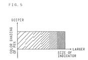
- FIG. 5 is a graph showing a relationship between the size of the indicator S calculated by the calculating unit 51 and shading of a color of the pen to be used for drawing an image such as a locus on the display screen 10.
- an object such as a writing brush whose thickness is changed continuously according to its pressing force and pressing direction
- its locus becomes thicker.
- the writing brush is actually used, when the strength of the brushstroke is increased, a deep line is drawn.
- the present embodiment can be realized by determining drawing depth at S14 according to a size of the indicator S calculated by the calculating unit 51 at S13 in the flow chart of FIG. 4.
- FIG. 6 is a graph showing a change with time in a size of the indicator S calculated by the calculating unit 51 and a method of drawing an image on the display screen 10 accordingly.
- a size of the indicator S calculated by the calculating unit 51 is not more than a certain threshold value TH between the time t1 and t2
- general drawing with a pen is selected, and a line, which has a color previously selected (or color of default) by an operator and thickness or depth according to a size of the indicator S calculated by the calculating unit 51, is drawn on the display screen 10.
- a size of the indicator S detected by the calculating unit 51 becomes not less than a certain threshold value TH between the time t2 and t3, a line with the same color as a background color is drawn on the display screen 10.
- a size of the locus at this time should be a thickness according to the threshold value TH.
- the erasing function In the state that the erasing function is operated, when the indicator S is removed from the display screen 10, more specifically it is removed from the detecting range of the indicator detector, in the case where an object such as an aforementioned writing brush whose thickness is continuously changed according to its pressing force or pressing direction is used as the indicator S, timing such that the result of calculating a size of the indicator S by the calculating unit 51 becomes smaller than the threshold value TH shown in FIG. 6 surely occurs. Therefore, at this timing, the erasing function is canceled, and the normal function for drawing with pen is returned.
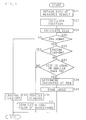
- FIG. 7 is a flow chart showing the processing procedure in the present embodiment.
- the calculating unit 51 obtains the data of one measured result ⁇ 1-1, ⁇ 1-2, ⁇ 2-1 and ⁇ 2-2 from the measuring means (S21), and it calculates a position of the indicator S (S22) and calculates a size of the indicator S (S23) based on the data.
- the calculating unit 51 judges as to whether or not a pen-down state is obtained (S25).
- the pen-down state is such a state that the indicator S is pressed down on the display screen 10 and a size of the indicator S can be normally calculated by the calculating unit 51.
- the calculating unit 51 judges "NO", namely, that the pen-down state is not obtained at S25, the calculating unit 51 turns the erasing flag to "OFF" and cancels the erasing function (S32). In this case, the image control unit 52 does not perform the drawing operation on the display screen 10.
- the calculating unit 51 judges "YES", namely, that the pen-down state is obtained at S25, the calculating unit 51 judges as to whether or not the erasing flag is "ON” (S26).
- the image control unit 52 keeps the erasing flag "ON” to perform the drawing operation using the same color as the background color (S30 and S31).
- the calculating unit 51 judges as to whether or not a calculated value of a size of the indicator S is not more than the threshold value TH (S27).
- a thickness of the pen namely, a thickness of a locus to be drawn on the display screen 10 is determined (S28), and the actual drawing operation is performed (S29).
- the calculating unit 51 turns the erasing flag to "ON" at S30 and makes the erasing function effective, and the drawing operation is performed using the same color as the background color at S31.
- the above processing is repeated every time data are given from the measuring means to the calculating unit 51 and image control unit 52.
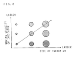
- FIG. 8 is a graph showing a relationship between a size and moving velocity of the indicator S calculated by the calculating unit 51 and a thickness of the pen (or shading) used for drawing on the display screen 10.
- the information displaying apparatus of the present invention can detect the position and size of the indicator S in time series. Moreover, the moving velocity and moving direction of the indicator S can be also calculated from the change with time in the position of the indicator S. Therefore, in the present embodiment, by drawing a locus whose thickness is in proportion to the size of the indicator S or whose depth is in inverse proportion to the moving velocity of the indicator S on the display screen 10, a state such that a character is written by a writing brush is reproduced.
- a thick line can be drawn by increasing the strength of a brushstroke to crush the point of the writing brush.
- a blurred or thin line can be drawn by increasing the velocity of the point of the writing brush.
- the present embodiment can show the effects of the thickness and shading of a color obtained in such a manner a line is drawn by actually using a writing brush.
- FIG. 9 is a flow chart showing the processing procedure in the present embodiment.
- the calculating unit 51 obtains data of one measured result ⁇ 1-1, ⁇ 1-2, ⁇ 2-1 and ⁇ 2-2 from the measuring means (S41), and a position of the indicator S is calculated (S42) and a size of the indicator S is calculated (S43) based on the data. Further, a moving velocity of the indicator S is calculated (S44). When the moving velocity of the indicator S is calculated, the image control unit 52 determines a thickness of the pen according to the size of the indicator (S45) and determines shading of the pen according to the moving velocity of the indicator S (S46).
- the optical indicator detector for detecting the position and size of the indicator is used. It is not to say, however, other optical detector such as abovementioned Carol method, and the like, further, methods besides optical method such as an ultrasonic surface acoustic wave method, or a pressure sensitive method using electric resistance or capacity change, and the like may be used.
- a thickness of one line can be changed and can be changed in steps during the drawing.
- the so-called erasing function for erasing a portion which has been once drawn can be also started without special operation. Further, subtle blur obtained by drawing an image with a writing brush dripped (dipped) in the ink can be expressed.
Landscapes
- Engineering & Computer Science (AREA)
- General Engineering & Computer Science (AREA)
- Theoretical Computer Science (AREA)
- Human Computer Interaction (AREA)
- Physics & Mathematics (AREA)
- General Physics & Mathematics (AREA)
- Position Input By Displaying (AREA)
- User Interface Of Digital Computer (AREA)
Applications Claiming Priority (2)
| Application Number | Priority Date | Filing Date | Title |
|---|---|---|---|
| JP23754197A JPH1185377A (ja) | 1997-09-02 | 1997-09-02 | 光学式位置検出装置付き情報表示装置 |
| JP237541/97 | 1997-09-02 |
Publications (2)
| Publication Number | Publication Date |
|---|---|
| EP0901065A2 true EP0901065A2 (fr) | 1999-03-10 |
| EP0901065A3 EP0901065A3 (fr) | 2006-04-19 |
Family
ID=17016868
Family Applications (1)
| Application Number | Title | Priority Date | Filing Date |
|---|---|---|---|
| EP98301604A Withdrawn EP0901065A3 (fr) | 1997-09-02 | 1998-03-04 | Appareil d'affichage d'information |
Country Status (4)
| Country | Link |
|---|---|
| US (1) | US6268868B1 (fr) |
| EP (1) | EP0901065A3 (fr) |
| JP (1) | JPH1185377A (fr) |
| CN (1) | CN1139869C (fr) |
Cited By (4)
| Publication number | Priority date | Publication date | Assignee | Title |
|---|---|---|---|---|
| WO2006004983A3 (fr) * | 2004-06-30 | 2006-04-06 | Nat Semiconductor Corp | Appareil et procede permettant d'effectuer la saisie de donnees au moyen d'ecrans d'affichage a touches lumineuses |
| US7551814B1 (en) | 2006-02-21 | 2009-06-23 | National Semiconductor Corporation | Optical detection of user interaction based on external light source |
| JP2012073857A (ja) * | 2010-09-29 | 2012-04-12 | Copcom Co Ltd | 画像処理プログラム、及び画像処理装置 |
| EP3660641A1 (fr) * | 2018-11-27 | 2020-06-03 | Samsung Electronics Co., Ltd. | Appareil d'affichage et son procédé de commande |
Families Citing this family (15)
| Publication number | Priority date | Publication date | Assignee | Title |
|---|---|---|---|---|
| JP3830121B2 (ja) | 1999-06-10 | 2006-10-04 | 株式会社 ニューコム | 物体検出用光学ユニット及びそれを用いた位置座標入力装置 |
| WO2001057635A1 (fr) * | 2000-02-02 | 2001-08-09 | Fujitsu Limited | Detecteur de position optique |
| JP4393030B2 (ja) * | 2000-04-14 | 2010-01-06 | 富士通株式会社 | 光学式位置検出装置及び記録媒体 |
| US7158136B2 (en) * | 2002-11-04 | 2007-01-02 | Honeywell International, Inc. | Methods and apparatus for displaying multiple data categories |
| US7292245B2 (en) * | 2004-01-20 | 2007-11-06 | Sensitron, Inc. | Method and apparatus for time series graph display |
| US20060262105A1 (en) * | 2005-05-18 | 2006-11-23 | Microsoft Corporation | Pen-centric polyline drawing tool |
| JP5224973B2 (ja) * | 2008-08-26 | 2013-07-03 | 株式会社ジャパンディスプレイウェスト | 情報入出力装置および情報入出力方法 |
| US20100207909A1 (en) * | 2009-02-13 | 2010-08-19 | Ming-Cho Wu | Detection module and an optical detection device comprising the same |
| TWI452488B (zh) * | 2009-05-18 | 2014-09-11 | Pixart Imaging Inc | 應用於感測系統的控制方法 |
| WO2012121277A1 (fr) * | 2011-03-09 | 2012-09-13 | コクヨ株式会社 | Système de présentation |
| TWI511003B (zh) * | 2011-12-05 | 2015-12-01 | Wistron Corp | 光學觸控裝置及其邊框 |
| JP2015088147A (ja) * | 2013-11-03 | 2015-05-07 | 西日本旅客鉄道株式会社 | タッチパネル入力装置及び入力処理プログラム |
| WO2017013957A1 (fr) * | 2015-07-17 | 2017-01-26 | 富士電機株式会社 | Panneau tactile optique, structure anti-reflet pour surface intérieure de couvercle, et machine de vente |
| CN106886304A (zh) * | 2017-02-20 | 2017-06-23 | 联想(北京)有限公司 | 数据处理方法、触控笔应用客户端以及电子设备 |
| CN109109634A (zh) * | 2018-07-16 | 2019-01-01 | 常州星宇车灯股份有限公司 | 一种具有可伸缩柔性显示屏的汽车天窗 |
Family Cites Families (16)
| Publication number | Priority date | Publication date | Assignee | Title |
|---|---|---|---|---|
| US3727069A (en) * | 1971-07-21 | 1973-04-10 | Litton Systems Inc | Target measurement system for precise projectile location |
| US4267443A (en) | 1978-04-24 | 1981-05-12 | Carroll Manufacturing Corporation | Photoelectric input apparatus |
| US4420261A (en) * | 1980-09-02 | 1983-12-13 | Lowbar, Inc. | Optical position location apparatus |
| US4507557A (en) * | 1983-04-01 | 1985-03-26 | Siemens Corporate Research & Support, Inc. | Non-contact X,Y digitizer using two dynamic ram imagers |
| SE8602233L (sv) * | 1985-06-05 | 1986-12-06 | Illinois Tool Works | Optisk legesbestemningsanordning |
| US4811004A (en) * | 1987-05-11 | 1989-03-07 | Dale Electronics, Inc. | Touch panel system and method for using same |
| JPH01112321A (ja) * | 1987-10-27 | 1989-05-01 | Canon Inc | 画像検知装置 |
| JP2814490B2 (ja) * | 1988-04-19 | 1998-10-22 | ソニー株式会社 | 座標入力装置 |
| EP0563477A1 (fr) * | 1992-03-25 | 1993-10-06 | Visage Inc. | Appareil capteur pour un écran tactile |
| JP3289072B2 (ja) * | 1993-12-22 | 2002-06-04 | 株式会社セガ | ベクトル入力装置 |
| JPH07200133A (ja) * | 1993-12-28 | 1995-08-04 | Casio Comput Co Ltd | ペン入力装置 |
| JPH07325658A (ja) * | 1994-06-01 | 1995-12-12 | Mitsubishi Electric Corp | 筆圧検出装置及びペン入力データ処理装置 |
| JPH0887372A (ja) * | 1994-09-16 | 1996-04-02 | Toshiba Corp | 画像入力装置 |
| JPH08335134A (ja) * | 1995-06-07 | 1996-12-17 | Canon Inc | 情報処理装置 |
| US5635724A (en) * | 1995-06-07 | 1997-06-03 | Intecolor | Method and apparatus for detecting the location of an object on a surface |
| JP3522399B2 (ja) * | 1995-08-11 | 2004-04-26 | シャープ株式会社 | 情報処理装置 |
-
1997
- 1997-09-02 JP JP23754197A patent/JPH1185377A/ja active Pending
-
1998
- 1998-02-26 US US09/031,190 patent/US6268868B1/en not_active Expired - Lifetime
- 1998-03-04 EP EP98301604A patent/EP0901065A3/fr not_active Withdrawn
- 1998-03-12 CN CNB981055486A patent/CN1139869C/zh not_active Expired - Fee Related
Cited By (4)
| Publication number | Priority date | Publication date | Assignee | Title |
|---|---|---|---|---|
| WO2006004983A3 (fr) * | 2004-06-30 | 2006-04-06 | Nat Semiconductor Corp | Appareil et procede permettant d'effectuer la saisie de donnees au moyen d'ecrans d'affichage a touches lumineuses |
| US7551814B1 (en) | 2006-02-21 | 2009-06-23 | National Semiconductor Corporation | Optical detection of user interaction based on external light source |
| JP2012073857A (ja) * | 2010-09-29 | 2012-04-12 | Copcom Co Ltd | 画像処理プログラム、及び画像処理装置 |
| EP3660641A1 (fr) * | 2018-11-27 | 2020-06-03 | Samsung Electronics Co., Ltd. | Appareil d'affichage et son procédé de commande |
Also Published As
| Publication number | Publication date |
|---|---|
| CN1139869C (zh) | 2004-02-25 |
| JPH1185377A (ja) | 1999-03-30 |
| US6268868B1 (en) | 2001-07-31 |
| EP0901065A3 (fr) | 2006-04-19 |
| CN1210303A (zh) | 1999-03-10 |
Similar Documents
| Publication | Publication Date | Title |
|---|---|---|
| US6268868B1 (en) | Information displaying apparatus | |
| US8847924B2 (en) | Reflecting light | |
| EP1132852B1 (fr) | Dispositif optique pour l'entrée/détection de coordonnées avec une fonction de correction d'erreur de positionnement de l'unité optique | |
| EP2280335A2 (fr) | Appareil de détection de la position optique et appareil d'affichage doté de la fonction de détection de la position | |
| US7432914B2 (en) | Coordinate input apparatus, its control method, and program | |
| JP4083941B2 (ja) | 座標入力装置 | |
| US20020145595A1 (en) | Information input/output apparatus, information input/output control method, and computer product | |
| JP4442877B2 (ja) | 座標入力装置およびその制御方法 | |
| EP1083514A1 (fr) | Appareil pour l'entrée/détection de coordonnées, méthode et produit de logiciel informatique | |
| KR20030004083A (ko) | 영상의 실시간 보정 방법 및 시스템 | |
| JP2001282445A (ja) | 座標入力/検出装置および情報表示入力装置 | |
| US20080291179A1 (en) | Light Pen Input System and Method, Particularly for Use with Large Area Non-Crt Displays | |
| EP2280336A2 (fr) | Appareil de détection de la position optique et appareil d'affichage doté de la fonction de détection de la position | |
| JP2002268810A (ja) | 座標入力装置 | |
| JP2003280802A (ja) | 座標入力装置 | |
| CN102132239B (zh) | 交互式显示屏 | |
| JP4560224B2 (ja) | 情報入力装置、情報入出力システム、プログラム及び記憶媒体 | |
| JP2003276399A (ja) | 位置検出方法および装置ならびに電子黒板装置 | |
| JP2002342015A (ja) | 情報入力装置及び情報入出力システム | |
| JP4011260B2 (ja) | 座標検出装置、電子黒板システム、座標位置検出方法及び記憶媒体 | |
| JP2003330612A (ja) | 情報入出力システム、プログラムおよび記憶媒体 | |
| JP4603183B2 (ja) | 情報入出力システム、表示制御方法、記憶媒体およびプログラム | |
| JPH11184618A (ja) | 光走査型タッチパネル | |
| JP4080136B2 (ja) | 座標入力/検出装置及び記憶媒体 | |
| JP2008217819A (ja) | 情報入力装置、情報入力方法、情報入力プログラム及び記憶媒体 |
Legal Events
| Date | Code | Title | Description |
|---|---|---|---|
| PUAI | Public reference made under article 153(3) epc to a published international application that has entered the european phase |
Free format text: ORIGINAL CODE: 0009012 |
|
| AK | Designated contracting states |
Kind code of ref document: A2 Designated state(s): AT BE CH DE DK ES FI FR GB GR IE IT LI LU MC NL PT SE |
|
| AX | Request for extension of the european patent |
Free format text: AL;LT;LV;MK;RO;SI |
|
| PUAL | Search report despatched |
Free format text: ORIGINAL CODE: 0009013 |
|
| AK | Designated contracting states |
Kind code of ref document: A3 Designated state(s): AT BE CH DE DK ES FI FR GB GR IE IT LI LU MC NL PT SE |
|
| AX | Request for extension of the european patent |
Extension state: AL LT LV MK RO SI |
|
| AKX | Designation fees paid | ||
| REG | Reference to a national code |
Ref country code: DE Ref legal event code: 8566 |
|
| STAA | Information on the status of an ep patent application or granted ep patent |
Free format text: STATUS: THE APPLICATION IS DEEMED TO BE WITHDRAWN |
|
| 18D | Application deemed to be withdrawn |
Effective date: 20061020 |