EP0901139A2 - Unterbrechungsvorrichtung - Google Patents
Unterbrechungsvorrichtung Download PDFInfo
- Publication number
- EP0901139A2 EP0901139A2 EP98116666A EP98116666A EP0901139A2 EP 0901139 A2 EP0901139 A2 EP 0901139A2 EP 98116666 A EP98116666 A EP 98116666A EP 98116666 A EP98116666 A EP 98116666A EP 0901139 A2 EP0901139 A2 EP 0901139A2
- Authority
- EP
- European Patent Office
- Prior art keywords
- lever
- moving electrode
- spring member
- breaker device
- electrode
- Prior art date
- Legal status (The legal status is an assumption and is not a legal conclusion. Google has not performed a legal analysis and makes no representation as to the accuracy of the status listed.)
- Granted
Links
Images


Classifications
-
- H—ELECTRICITY
- H01—ELECTRIC ELEMENTS
- H01H—ELECTRIC SWITCHES; RELAYS; SELECTORS; EMERGENCY PROTECTIVE DEVICES
- H01H21/00—Switches operated by an operating part in the form of a pivotable member acted upon directly by a solid body, e.g. by a hand
- H01H21/02—Details
- H01H21/18—Movable parts; Contacts mounted thereon
- H01H21/36—Driving mechanisms
- H01H21/40—Driving mechanisms having snap action
- H01H21/42—Driving mechanisms having snap action produced by compression or extension of coil spring
-
- H—ELECTRICITY
- H01—ELECTRIC ELEMENTS
- H01H—ELECTRIC SWITCHES; RELAYS; SELECTORS; EMERGENCY PROTECTIVE DEVICES
- H01H19/00—Switches operated by an operating part which is rotatable about a longitudinal axis thereof and which is acted upon directly by a solid body external to the switch, e.g. by a hand
- H01H19/54—Switches operated by an operating part which is rotatable about a longitudinal axis thereof and which is acted upon directly by a solid body external to the switch, e.g. by a hand the operating part having at least five or an unspecified number of operative positions
- H01H19/60—Angularly-movable actuating part carrying no contacts
- H01H19/635—Contacts actuated by rectilinearly-movable member linked to operating part, e.g. by pin and slot
Definitions
- This torsion coil spring 6 is resiliently deformed or bent in such a manner that the angle between the two arms 6A and 6B is reduced, and the lever 5 is urged in the disconnecting direction by a resilient restoring force thereof.
- a tilting pivot of the lever is displaceable in the same directions as the directions of connection and disconnection of the electrodes.
- the tilting pivot of the lever is displaced in the directions of connection and disconnection of the electrodes, and therefore as compared with a construction in which a lever is tilted about a fixed pivot, the lever is tilted at a larger angle in the connected position and the disconnected position. Therefore, the size of the device in the direction of its height can be reduced.
- the moving electrode is kept urged in the connected direction even when the moving electrode is connected to the fixed electrode, and therefore even if a small external force is applied in the disconnecting direction, the moving electrode is held in the connected condition, and the connection is reliability high.
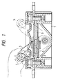
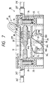
- the casing 10 comprises a casing body 11 of a rectangular parallelepiped shape with an open top, and a panel 12 attached to the casing body 11 to close this open top.
- the casing 10 is fixedly mounted in a vehicle body of the electric car through leg portions 13 (see Fig. 5) provided respectively at four corner portions of the casing body 11.
- the interior of the casing body 11 is divided into three chambers by two partition walls (see Fig. 5).
- the intermediate chamber serves as an electrode receiving space 14 for receiving the electrode unit 20.
- the front and rear chambers serve as lever support spaces 15 for supporting the lever 35.
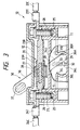
- a hook 34L, formed at a lower end of a tension coil spring 33 (i.e., spring member that is a constituent element of the present invention) is retained on this fixed spring retaining portion 32.
- a hook 34U at the upper end of the tension coil spring 33 is retained on the arm 36 of the lever 35 (to be described later).
- the lever 35 is made of a synthetic resin, and has a handle portion 37 extending between the pair of arms 36, so that the lever 35 has a gate-like configuration as a whole.
- the lever 35 is provided astride the electrode unit 20, and the lower end portions of the two arms 36 are received respectively in the lever support spaces 15 (see Fig. 5).
- a slot 38 is formed through that portion of each am 36 disposed generally centrally of the length thereof, and the connecting shaft 28 of the moving electrode 21M is fitted in the slot 38 so as to be displaced relative thereto.
- a movable spring retaining portion 39 is formed on that portion of the arm 36 disposed below the slot 38, and the hook 34U at the upper end of the tension coil spring 33 is engaged with this spring retaining portion 39.
- each of the two arms 36 serves as a pivot 36A about which the lever 35 can be tilted.
- This arcuate lower end can smoothly slide over the guide surface 29 in the right-left direction intersecting the direction of extension and contraction of the tension coil spring 33.
- the urging direction of the tension coil spring 33 is the connecting direction or the disconnecting direction is determined by the position of the tilting pivot 36A of the lever 35 relative to the fixed spring retaining portion 32 and by the angle of the arm 36 relative to the guide surface 29. Namely, when the tilting pivot 36A is disposed on the right side of the fixed spring retaining portion 32, and also the arm 36 is tilted left from a plane perpendicular to the guide surface 29 as shown in Fig. 3, the urging direction is the direction for tilting the lever 35 leftward.
- the lever 35 can be urged in either of the connecting direction and the disconnecting direction by the tension coil springs 33. Therefore, the two fixed electrodes 21L and 21R are prevented from being held in an incompletely-connected condition, and can be held in either of the completely-connected condition and the completely-disconnected condition.
- rollers may be provided at the lower end of the lever 35, in which case the rollers roll respectively over the guide surfaces 29 in accordance with the tilting movement of the lever.
- a breaker device of this embodiment is provided for opening and closing a main power circuit connecting a battery (not shown) to various electronic equipment in an electric car.
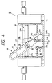
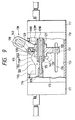
- An electrode unit 120 which is received in a casing 110 of a synthetic resin, is brought into a fitted condition and a disengaged condition by pivotally moving a lever 138.
- the casing 110 has a box-shape, and is fixedly mounted in a vehicle body of the electric car through mounting portions 111 (see Fig. 10) provided respectively at four corner portions of the casing 110.
- the interior of the casing 110 is divided into three chambers by two partition walls 112 (see Fig. 10).
- the intermediate chamber serves as an electrode receiving space 113 for receiving the electrode unit 120, and the front and rear chambers serve as lever support spaces 114 for receiving the lever 138.
- each of the two partition walls 112 is formed into a guide 115.
- the guide 115 When viewed from the top, the guide 115 is parallel to a path of movement of a moving electrode (described later) from a connected position to a disconnected position (see Fig. 10).
- the guide 115 When viewed from the front side, on the other hand, the guide 115 has a mountain-like shape having a peak at a position 115P disposed midway along the direction of the path of movement of the moving electrode 121M (see Figs. 11 and 12).
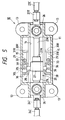
- the electrode unit 120 includes a pair of left and right fixed electrodes 121L and 121R one of which is longer than the other, and the moving electrode 121M slidably fitted on the outer peripheries of these fixed electrodes.
- the two fixed electrodes 121L and 21R are each in the form of a round rod, and their distal ends are opposed to each other.
- the two fixed electrodes 121L and 121R are interconnected by a connecting rod 122 made of a non-electrically-conductive synthetic resin, and therefore are integrally connected together, and are insulatingly spaced a predetermined distance from each other on a common axis extending in a right-left direction.
- Upper hooks 137A of tension coil springs 135 i.e., spring members that are constituent elements of the present invention are retainingly engaged respectively with those portions of the movable pin 130 disposed outwardly respectively of the lever 138.
- a pin support portion 131 is formed on, and projects downwardly from the connecting member 127, and the pair of front and rear fixed pins 132 are formed on this pin support portion 131.
- the fixed pins 132 extend respectively through the slits 116 as described above, and lower hooks 137B of the tension coil springs 135 are retainingly engaged respectively with the projected ends of the fixed pins 132.
- each of the spring members comprises the tension coil spring 135, and therefore the spring members will not be buckled in contrast with the case where the spring member comprise a compression coil spring. Namely, the function of urging the moving electrode 121M is highly reliable.
Landscapes
- Driving Mechanisms And Operating Circuits Of Arc-Extinguishing High-Tension Switches (AREA)
- Mechanisms For Operating Contacts (AREA)
Applications Claiming Priority (6)
| Application Number | Priority Date | Filing Date | Title |
|---|---|---|---|
| JP23995297 | 1997-09-04 | ||
| JP239952/97 | 1997-09-04 | ||
| JP23995297A JPH1186687A (ja) | 1997-09-04 | 1997-09-04 | ブレーカ装置 |
| JP9285499A JPH11120886A (ja) | 1997-10-17 | 1997-10-17 | ブレーカ装置 |
| JP28549997 | 1997-10-17 | ||
| JP285499/97 | 1997-10-17 |
Publications (3)
| Publication Number | Publication Date |
|---|---|
| EP0901139A2 true EP0901139A2 (de) | 1999-03-10 |
| EP0901139A3 EP0901139A3 (de) | 1999-07-07 |
| EP0901139B1 EP0901139B1 (de) | 2002-05-29 |
Family
ID=26534513
Family Applications (1)
| Application Number | Title | Priority Date | Filing Date |
|---|---|---|---|
| EP98116666A Expired - Lifetime EP0901139B1 (de) | 1997-09-04 | 1998-09-03 | Unterbrechungsvorrichtung |
Country Status (3)
| Country | Link |
|---|---|
| US (1) | US6140597A (de) |
| EP (1) | EP0901139B1 (de) |
| DE (1) | DE69805581T2 (de) |
Cited By (2)
| Publication number | Priority date | Publication date | Assignee | Title |
|---|---|---|---|---|
| EP1003090A3 (de) * | 1998-11-19 | 2002-12-18 | Kabushiki Kaisha Tokai Rika Denki Seisakusho | Hebelschaltervorrichtung |
| CN102054630A (zh) * | 2010-12-01 | 2011-05-11 | 沈阳斯沃电器有限公司 | 大容量低压断路器用操作机构 |
Families Citing this family (1)
| Publication number | Priority date | Publication date | Assignee | Title |
|---|---|---|---|---|
| CN104992872B8 (zh) * | 2015-08-07 | 2017-07-14 | 国网浙江三门县供电公司 | 安全电力闸刀 |
Family Cites Families (9)
| Publication number | Priority date | Publication date | Assignee | Title |
|---|---|---|---|---|
| US1465412A (en) * | 1917-08-17 | 1923-08-21 | Crouse Hinds Co | Quick-break switch |
| US1781710A (en) * | 1929-07-25 | 1930-11-18 | Cutler Hammer Inc | Electric switch |
| US2028314A (en) * | 1934-03-06 | 1936-01-21 | Raylite Trading Company Inc | Switch-type plug attachment device |
| GB530622A (en) * | 1939-06-14 | 1940-12-17 | Crabtree & Co Ltd J A | Improvements in, and connected with, electric tumbler switches |
| US2467797A (en) * | 1943-07-24 | 1949-04-19 | Westinghouse Electric Corp | Circuit breaker |
| US2473263A (en) * | 1947-11-12 | 1949-06-14 | Gen Electric | Electric switch |
| US3483490A (en) * | 1968-08-19 | 1969-12-09 | Gen Electric | Electric circuit breaker with break-away coupling |
| US5911318A (en) * | 1996-12-16 | 1999-06-15 | Sumitomo Wiring Systems, Ltd. | Breaker device |
| JP3487104B2 (ja) * | 1996-12-16 | 2004-01-13 | 住友電装株式会社 | ブレーカ装置 |
-
1998
- 1998-08-28 US US09/143,512 patent/US6140597A/en not_active Expired - Fee Related
- 1998-09-03 DE DE69805581T patent/DE69805581T2/de not_active Expired - Fee Related
- 1998-09-03 EP EP98116666A patent/EP0901139B1/de not_active Expired - Lifetime
Cited By (2)
| Publication number | Priority date | Publication date | Assignee | Title |
|---|---|---|---|---|
| EP1003090A3 (de) * | 1998-11-19 | 2002-12-18 | Kabushiki Kaisha Tokai Rika Denki Seisakusho | Hebelschaltervorrichtung |
| CN102054630A (zh) * | 2010-12-01 | 2011-05-11 | 沈阳斯沃电器有限公司 | 大容量低压断路器用操作机构 |
Also Published As
| Publication number | Publication date |
|---|---|
| DE69805581D1 (de) | 2002-07-04 |
| EP0901139B1 (de) | 2002-05-29 |
| EP0901139A3 (de) | 1999-07-07 |
| DE69805581T2 (de) | 2003-01-16 |
| US6140597A (en) | 2000-10-31 |
Similar Documents
| Publication | Publication Date | Title |
|---|---|---|
| US11749926B2 (en) | Electrical connection device for vehicle | |
| US5435748A (en) | Connector with fitting detection function | |
| JP4272037B2 (ja) | レバー嵌合式電源回路遮断装置 | |
| JP3301522B2 (ja) | コネクタ | |
| JP4191725B2 (ja) | コネクタ装置 | |
| KR100216000B1 (ko) | 스위치를갖는전기커넥터조립체 | |
| CN115939860B (zh) | 连接器装置 | |
| EP0774803B1 (de) | Verbinder mit Verriegelungsarm | |
| KR102749301B1 (ko) | 커넥터 장치 | |
| EP0823757B1 (de) | Hebelartiger Steckverbinder | |
| US5385870A (en) | Detachable electrical plug connection | |
| US5980297A (en) | Lock arm deformation prevention construction | |
| US10340632B1 (en) | Electrical connector assembly with staged release | |
| EP1077456A2 (de) | Unterbrechungsvorrichtung | |
| US5702265A (en) | Connector structure | |
| US4516819A (en) | Make and break electrical connector | |
| US6140597A (en) | Breaker device having an incomplete-connection prevention function | |
| IE55122B1 (en) | Bipartite electrical connector housing | |
| EP1020884B1 (de) | Hebelschalter | |
| JP3678600B2 (ja) | ブレーカ装置 | |
| JPH10321292A (ja) | コネクタ | |
| CN116368591A (zh) | 微动开关 | |
| CN223245905U (zh) | 用于电路的触发结构、电子锁以及插座组件 | |
| JPH1186687A (ja) | ブレーカ装置 | |
| KR102576079B1 (ko) | 적층형 조인트 커넥터 |
Legal Events
| Date | Code | Title | Description |
|---|---|---|---|
| PUAI | Public reference made under article 153(3) epc to a published international application that has entered the european phase |
Free format text: ORIGINAL CODE: 0009012 |
|
| AK | Designated contracting states |
Kind code of ref document: A2 Designated state(s): DE FR GB |
|
| AX | Request for extension of the european patent |
Free format text: AL;LT;LV;MK;RO;SI |
|
| PUAL | Search report despatched |
Free format text: ORIGINAL CODE: 0009013 |
|
| AK | Designated contracting states |
Kind code of ref document: A3 Designated state(s): AT BE CH CY DE DK ES FI FR GB GR IE IT LI LU MC NL PT SE |
|
| AX | Request for extension of the european patent |
Free format text: AL;LT;LV;MK;RO;SI |
|
| 17P | Request for examination filed |
Effective date: 19990928 |
|
| AKX | Designation fees paid |
Free format text: DE FR GB |
|
| RTI1 | Title (correction) |
Free format text: BREAKER DEVICE HAVING AN INCOMPLETE CONNECTION PREVENTION FUNCTION |
|
| 17Q | First examination report despatched |
Effective date: 20010313 |
|
| GRAG | Despatch of communication of intention to grant |
Free format text: ORIGINAL CODE: EPIDOS AGRA |
|
| GRAG | Despatch of communication of intention to grant |
Free format text: ORIGINAL CODE: EPIDOS AGRA |
|
| GRAH | Despatch of communication of intention to grant a patent |
Free format text: ORIGINAL CODE: EPIDOS IGRA |
|
| GRAH | Despatch of communication of intention to grant a patent |
Free format text: ORIGINAL CODE: EPIDOS IGRA |
|
| GRAA | (expected) grant |
Free format text: ORIGINAL CODE: 0009210 |
|
| AK | Designated contracting states |
Kind code of ref document: B1 Designated state(s): DE FR GB |
|
| REG | Reference to a national code |
Ref country code: GB Ref legal event code: FG4D |
|
| REF | Corresponds to: |
Ref document number: 69805581 Country of ref document: DE Date of ref document: 20020704 |
|
| ET | Fr: translation filed | ||
| RAP2 | Party data changed (patent owner data changed or rights of a patent transferred) |
Owner name: SUMITOMO ELECTRIC INDUSTRIES, LTD. Owner name: SUMITOMO WIRING SYSTEMS, LTD. Owner name: AUTONETWORKS TECHNOLOGIES, LTD. |
|
| PLBE | No opposition filed within time limit |
Free format text: ORIGINAL CODE: 0009261 |
|
| STAA | Information on the status of an ep patent application or granted ep patent |
Free format text: STATUS: NO OPPOSITION FILED WITHIN TIME LIMIT |
|
| 26N | No opposition filed |
Effective date: 20030303 |
|
| PGFP | Annual fee paid to national office [announced via postgrant information from national office to epo] |
Ref country code: GB Payment date: 20030903 Year of fee payment: 6 |
|
| PGFP | Annual fee paid to national office [announced via postgrant information from national office to epo] |
Ref country code: FR Payment date: 20030909 Year of fee payment: 6 |
|
| PGFP | Annual fee paid to national office [announced via postgrant information from national office to epo] |
Ref country code: DE Payment date: 20030911 Year of fee payment: 6 |
|
| PG25 | Lapsed in a contracting state [announced via postgrant information from national office to epo] |
Ref country code: GB Free format text: LAPSE BECAUSE OF NON-PAYMENT OF DUE FEES Effective date: 20040903 |
|
| PG25 | Lapsed in a contracting state [announced via postgrant information from national office to epo] |
Ref country code: DE Free format text: LAPSE BECAUSE OF NON-PAYMENT OF DUE FEES Effective date: 20050401 |
|
| GBPC | Gb: european patent ceased through non-payment of renewal fee |
Effective date: 20040903 |
|
| PG25 | Lapsed in a contracting state [announced via postgrant information from national office to epo] |
Ref country code: FR Free format text: LAPSE BECAUSE OF NON-PAYMENT OF DUE FEES Effective date: 20050531 |
|
| REG | Reference to a national code |
Ref country code: FR Ref legal event code: ST |