EP0901210B1 - Elektrischer Scheibenhebeschalter und Hinderniserkennung/schutz mit vorrangiger Betätigung - Google Patents
Elektrischer Scheibenhebeschalter und Hinderniserkennung/schutz mit vorrangiger Betätigung Download PDFInfo
- Publication number
- EP0901210B1 EP0901210B1 EP98116578A EP98116578A EP0901210B1 EP 0901210 B1 EP0901210 B1 EP 0901210B1 EP 98116578 A EP98116578 A EP 98116578A EP 98116578 A EP98116578 A EP 98116578A EP 0901210 B1 EP0901210 B1 EP 0901210B1
- Authority
- EP
- European Patent Office
- Prior art keywords
- trap
- switch
- mode
- auto
- detent
- Prior art date
- Legal status (The legal status is an assumption and is not a legal conclusion. Google has not performed a legal analysis and makes no representation as to the accuracy of the status listed.)
- Expired - Lifetime
Links
- 238000000034 method Methods 0.000 claims description 9
- 230000033001 locomotion Effects 0.000 description 5
- 230000008901 benefit Effects 0.000 description 4
- 238000010586 diagram Methods 0.000 description 4
- 238000010276 construction Methods 0.000 description 3
- 238000012360 testing method Methods 0.000 description 3
- 239000004020 conductor Substances 0.000 description 2
- 238000013461 design Methods 0.000 description 2
- 238000010079 rubber tapping Methods 0.000 description 2
- 230000011664 signaling Effects 0.000 description 2
- 230000001960 triggered effect Effects 0.000 description 2
- 230000004075 alteration Effects 0.000 description 1
- 230000008859 change Effects 0.000 description 1
- 238000004891 communication Methods 0.000 description 1
- 230000003247 decreasing effect Effects 0.000 description 1
- 230000001419 dependent effect Effects 0.000 description 1
- 230000000694 effects Effects 0.000 description 1
- 238000009432 framing Methods 0.000 description 1
- 238000010438 heat treatment Methods 0.000 description 1
- 230000000977 initiatory effect Effects 0.000 description 1
- 230000010354 integration Effects 0.000 description 1
- 230000003340 mental effect Effects 0.000 description 1
- 238000012986 modification Methods 0.000 description 1
- 230000004048 modification Effects 0.000 description 1
- 230000002093 peripheral effect Effects 0.000 description 1
- 230000008569 process Effects 0.000 description 1
- 238000012545 processing Methods 0.000 description 1
- 230000000630 rising effect Effects 0.000 description 1
- 230000035945 sensitivity Effects 0.000 description 1
Images




Classifications
-
- E—FIXED CONSTRUCTIONS
- E05—LOCKS; KEYS; WINDOW OR DOOR FITTINGS; SAFES
- E05F—DEVICES FOR MOVING WINGS INTO OPEN OR CLOSED POSITION; CHECKS FOR WINGS; WING FITTINGS NOT OTHERWISE PROVIDED FOR, CONCERNED WITH THE FUNCTIONING OF THE WING
- E05F15/00—Power-operated mechanisms for wings
- E05F15/40—Safety devices, e.g. detection of obstructions or end positions
- E05F15/41—Detection by monitoring transmitted force or torque; Safety couplings with activation dependent upon torque or force, e.g. slip couplings
-
- E—FIXED CONSTRUCTIONS
- E05—LOCKS; KEYS; WINDOW OR DOOR FITTINGS; SAFES
- E05F—DEVICES FOR MOVING WINGS INTO OPEN OR CLOSED POSITION; CHECKS FOR WINGS; WING FITTINGS NOT OTHERWISE PROVIDED FOR, CONCERNED WITH THE FUNCTIONING OF THE WING
- E05F15/00—Power-operated mechanisms for wings
-
- E—FIXED CONSTRUCTIONS
- E05—LOCKS; KEYS; WINDOW OR DOOR FITTINGS; SAFES
- E05F—DEVICES FOR MOVING WINGS INTO OPEN OR CLOSED POSITION; CHECKS FOR WINGS; WING FITTINGS NOT OTHERWISE PROVIDED FOR, CONCERNED WITH THE FUNCTIONING OF THE WING
- E05F15/00—Power-operated mechanisms for wings
- E05F15/40—Safety devices, e.g. detection of obstructions or end positions
- E05F15/42—Detection using safety edges
-
- E—FIXED CONSTRUCTIONS
- E05—LOCKS; KEYS; WINDOW OR DOOR FITTINGS; SAFES
- E05Y—INDEXING SCHEME ASSOCIATED WITH SUBCLASSES E05D AND E05F, RELATING TO CONSTRUCTION ELEMENTS, ELECTRIC CONTROL, POWER SUPPLY, POWER SIGNAL OR TRANSMISSION, USER INTERFACES, MOUNTING OR COUPLING, DETAILS, ACCESSORIES, AUXILIARY OPERATIONS NOT OTHERWISE PROVIDED FOR, APPLICATION THEREOF
- E05Y2201/00—Constructional elements; Accessories therefor
- E05Y2201/40—Motors; Magnets; Springs; Weights; Accessories therefor
- E05Y2201/404—Function thereof
- E05Y2201/41—Function thereof for closing
-
- E—FIXED CONSTRUCTIONS
- E05—LOCKS; KEYS; WINDOW OR DOOR FITTINGS; SAFES
- E05Y—INDEXING SCHEME ASSOCIATED WITH SUBCLASSES E05D AND E05F, RELATING TO CONSTRUCTION ELEMENTS, ELECTRIC CONTROL, POWER SUPPLY, POWER SIGNAL OR TRANSMISSION, USER INTERFACES, MOUNTING OR COUPLING, DETAILS, ACCESSORIES, AUXILIARY OPERATIONS NOT OTHERWISE PROVIDED FOR, APPLICATION THEREOF
- E05Y2201/00—Constructional elements; Accessories therefor
- E05Y2201/40—Motors; Magnets; Springs; Weights; Accessories therefor
- E05Y2201/43—Motors
-
- E—FIXED CONSTRUCTIONS
- E05—LOCKS; KEYS; WINDOW OR DOOR FITTINGS; SAFES
- E05Y—INDEXING SCHEME ASSOCIATED WITH SUBCLASSES E05D AND E05F, RELATING TO CONSTRUCTION ELEMENTS, ELECTRIC CONTROL, POWER SUPPLY, POWER SIGNAL OR TRANSMISSION, USER INTERFACES, MOUNTING OR COUPLING, DETAILS, ACCESSORIES, AUXILIARY OPERATIONS NOT OTHERWISE PROVIDED FOR, APPLICATION THEREOF
- E05Y2400/00—Electronic control; Electrical power; Power supply; Power or signal transmission; User interfaces
- E05Y2400/10—Electronic control
- E05Y2400/52—Safety arrangements associated with the wing motor
- E05Y2400/525—Car-jacking prevention
-
- E—FIXED CONSTRUCTIONS
- E05—LOCKS; KEYS; WINDOW OR DOOR FITTINGS; SAFES
- E05Y—INDEXING SCHEME ASSOCIATED WITH SUBCLASSES E05D AND E05F, RELATING TO CONSTRUCTION ELEMENTS, ELECTRIC CONTROL, POWER SUPPLY, POWER SIGNAL OR TRANSMISSION, USER INTERFACES, MOUNTING OR COUPLING, DETAILS, ACCESSORIES, AUXILIARY OPERATIONS NOT OTHERWISE PROVIDED FOR, APPLICATION THEREOF
- E05Y2400/00—Electronic control; Electrical power; Power supply; Power or signal transmission; User interfaces
- E05Y2400/10—Electronic control
- E05Y2400/52—Safety arrangements associated with the wing motor
- E05Y2400/53—Wing impact prevention or reduction
- E05Y2400/54—Obstruction or resistance detection
- E05Y2400/57—Disabling thereof
-
- E—FIXED CONSTRUCTIONS
- E05—LOCKS; KEYS; WINDOW OR DOOR FITTINGS; SAFES
- E05Y—INDEXING SCHEME ASSOCIATED WITH SUBCLASSES E05D AND E05F, RELATING TO CONSTRUCTION ELEMENTS, ELECTRIC CONTROL, POWER SUPPLY, POWER SIGNAL OR TRANSMISSION, USER INTERFACES, MOUNTING OR COUPLING, DETAILS, ACCESSORIES, AUXILIARY OPERATIONS NOT OTHERWISE PROVIDED FOR, APPLICATION THEREOF
- E05Y2400/00—Electronic control; Electrical power; Power supply; Power or signal transmission; User interfaces
- E05Y2400/80—User interfaces
- E05Y2400/85—User input means
- E05Y2400/856—Actuation thereof
- E05Y2400/858—Actuation thereof by body parts, e.g. by feet
- E05Y2400/86—Actuation thereof by body parts, e.g. by feet by hand
-
- E—FIXED CONSTRUCTIONS
- E05—LOCKS; KEYS; WINDOW OR DOOR FITTINGS; SAFES
- E05Y—INDEXING SCHEME ASSOCIATED WITH SUBCLASSES E05D AND E05F, RELATING TO CONSTRUCTION ELEMENTS, ELECTRIC CONTROL, POWER SUPPLY, POWER SIGNAL OR TRANSMISSION, USER INTERFACES, MOUNTING OR COUPLING, DETAILS, ACCESSORIES, AUXILIARY OPERATIONS NOT OTHERWISE PROVIDED FOR, APPLICATION THEREOF
- E05Y2800/00—Details, accessories and auxiliary operations not otherwise provided for
- E05Y2800/25—Emergency conditions
- E05Y2800/252—Emergency conditions the elements functioning only in case of emergency
-
- E—FIXED CONSTRUCTIONS
- E05—LOCKS; KEYS; WINDOW OR DOOR FITTINGS; SAFES
- E05Y—INDEXING SCHEME ASSOCIATED WITH SUBCLASSES E05D AND E05F, RELATING TO CONSTRUCTION ELEMENTS, ELECTRIC CONTROL, POWER SUPPLY, POWER SIGNAL OR TRANSMISSION, USER INTERFACES, MOUNTING OR COUPLING, DETAILS, ACCESSORIES, AUXILIARY OPERATIONS NOT OTHERWISE PROVIDED FOR, APPLICATION THEREOF
- E05Y2900/00—Application of doors, windows, wings or fittings thereof
- E05Y2900/50—Application of doors, windows, wings or fittings thereof for vehicles
- E05Y2900/53—Type of wing
- E05Y2900/55—Windows
-
- H—ELECTRICITY
- H01—ELECTRIC ELEMENTS
- H01H—ELECTRIC SWITCHES; RELAYS; SELECTORS; EMERGENCY PROTECTIVE DEVICES
- H01H23/00—Tumbler or rocker switches, i.e. switches characterised by being operated by rocking an operating member in the form of a rocker button
- H01H23/003—Tumbler or rocker switches, i.e. switches characterised by being operated by rocking an operating member in the form of a rocker button with more than one electrically distinguishable condition in one or both positions
-
- H—ELECTRICITY
- H02—GENERATION; CONVERSION OR DISTRIBUTION OF ELECTRIC POWER
- H02H—EMERGENCY PROTECTIVE CIRCUIT ARRANGEMENTS
- H02H7/00—Emergency protective circuit arrangements specially adapted for specific types of electric machines or apparatus or for sectionalised protection of cable or line systems, and effecting automatic switching in the event of an undesired change from normal working conditions
- H02H7/08—Emergency protective circuit arrangements specially adapted for specific types of electric machines or apparatus or for sectionalised protection of cable or line systems, and effecting automatic switching in the event of an undesired change from normal working conditions for dynamo-electric motors
- H02H7/085—Emergency protective circuit arrangements specially adapted for specific types of electric machines or apparatus or for sectionalised protection of cable or line systems, and effecting automatic switching in the event of an undesired change from normal working conditions for dynamo-electric motors against excessive load
- H02H7/0851—Emergency protective circuit arrangements specially adapted for specific types of electric machines or apparatus or for sectionalised protection of cable or line systems, and effecting automatic switching in the event of an undesired change from normal working conditions for dynamo-electric motors against excessive load for motors actuating a movable member between two end positions, e.g. detecting an end position or obstruction by overload signal
Definitions
- the subject invention pertains to the art of control systems, particularly automotive control systems, and is specifically directed to switch systems for power opening and closing the window of an automobile.
- the invention is applicable to a simple and convenient switch system which accommodates anti-trap protection in the closing of an automobile window, yet includes override of the anti-trap protection to allow for a deliberate closing of the window even when an obstruction is present.
- the invention could be readily adapted for use in other environments, as for example, where similar anti-trap systems are employed to protect against potentially dangerous accidental closings where such anti-trap protection needs to be disabled in certain circumstances.
- Conventional automobile power windows comprise a switch control wherein raising the window for closure requires a "manual" operation wherein the up switch must be manually held in an activated state to power the window motor. When this switch is released by an operator, window movement ceases.
- the switch is disposed on an arm rest or side panel of the door framing the window, but it is also well known to dispose switch controls for non-driver windows at the driver location.
- the problem with such manual switch systems is that they require a portion of the operator's physical and mental attention during their operation and so present somewhat of a safety concern. Ease of use and convenience are also design goals.
- Automatic modes of window operation have been limited to an automatic down (“AUTO DOWN") wherein special operation of the control switch will allow the operator to manually release the switch while signaling that the window should continue with the opening operation.
- the AUTO DOWN mode permits the vehicle operator to fully open the window with minimal manual and physical attention.
- Known modes initiating such AUTO DOWN functions are a second detent in the switch assembly, or a time based switching including a short tap or an extended tap.
- AUTO UP also involves a serious safety concern when the window proceeds to closure for a portion of the time without direct operator supervision. It is reasonably foreseeable that a passenger or an object could be accidentally pinched between the window and its peripheral seal. Where the most likely candidate for such a pinching result is the hand or fingers of a child, thus has an unacceptable risk as a commercially feasible design feature.
- BMW "Betriebsan Extrem", BMW AG, München, 1993, XP002103268, pages 54-55, discloses a control system for power windows and was used as a basis for the preamble of claims 1 and 6.
- the present invention solves this problem by providing a control system as set forth in claims 1 or 6 and a method as set forth in claim 9. Preferred embodiments of the invention may be gathered from the dependent claims.
- the present invention contemplates a new and improved switch control system that can provide an AUTO UP mode for window operation, with both an anti-trap system for detecting and protecting an obstruction during window closure in MANUAL UP or AUTO UP modes and also an override of the anti-trap system to provide for manual closure even when an intended obstruction is present.
- a benefit of the present invention is a control system which allows an operator to readily distinguish, with mere tactile sensitivity, a switch being in the state where anti-trap is enabled from the state where the anti-trap is disabled.
- FIGURE 1 shows a control circuit 10 for controlling operation of a motor 12 for power opening and closing of a window in an automobile. Since power windows are well-known in autos, the specific operation of the motor including the details of the power switches 14 used for direct application of current thereto are not discussed in detail herein.
- the invention comprises novel control inputs and their processing to effect an improved window control system which allows an AUTO UP window operation with anti-trap protection, or with the anti-trap protection overridden. More particularly, operator inputs to the control system are effected by up/down switches 16, 18 and an anti-trap override switch 20 . An additional input comes from the obstacle detect sensor 22, which can sense when an object is obstructing closing of the window, such as in an accidental placement of a finger between the window and the seal.
- FIGURES 2A and 2B illustrate a window construction and the actual structure of the sensor 22 .
- Window 26 is normally received in a door frame seal 28 without contacting the sensor switch 22, but when an obstruction is interposed between the top of the window and the seal 28 , the sensor switch 22 is deformed to effectively cause the closing of the sensor switch which is recognizable by the control system as an anti-trap signal.
- sensor switch 22 comprises a flexible conduit 30 encasing spaced and opposed flexible wires 32 and 34 included in a casing of a conductive material 36, 38, respectively, and spaced by an air gap 40.
- a logic circuit 50 preferably comprising an ASIC (application specific integration circuit) or a processor, which can process the various input signals and control the motor 12 in a manner as will be detailed below.
- ASIC application specific integration circuit
- the last input to the logic circuit 50 comprises a current sensor 15 which allows the logic circuit to determine when to disconnect power to the motor when a window reaches its end of travel so that it is fully opened or fully closed in an AUTO DOWN or AUTO UP operating mode (i.e., "stall").
- a change in current to the motor is sensed and the logic circuit can disconnect the applied power.
- the switches 16, 18 and 20 are physically embodied in a switch construction such as shown therein.
- a switch construction such as shown therein.
- the switches 16, 18 and 20 are physically embodied in a switch construction such as shown therein.
- the toggle 54 when toggle 54 is tilted towards down contacts 56 so that the contacts are in electrical connection, down switch 18 is closed.
- the toggle 54 is levered towards the up contacts 58 so that they contact, the up switch 16 is closed.
- the toggle is pressed harder after either the up or down contacts are closed, then the opposing contact switch is also closed to obtain a second detent.
- the higher force required to actuate the second detent is easily recognizable by an operator and provides a safety feature.
- a third detent can be added in a similar fashion.
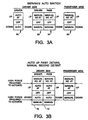
- FIGURES 3A-3C shown various switch arrangements for the subject invention as it could be implemented in an actual vehicle.
- FIGURE 3A shows a first embodiment comprised of toggles 60, 62, 64, 66.
- the driver's side switches 60, 62, 64 comprise a conventional control switch panel as is well known in that the driver can control both the driver window and the passenger window via toggling the switches to either UP or DOWN Switches 62, 64 and convey no AUTO UP or AUTO DOWN operation, nor have any anti-trap protection.
- the passenger side switch 66 is identical to switches 62, 64 .
- FIGURE 3A also illustrates a separately disposed auto switch 60 on the driver's side, wherein the driver can further implement an AUTO UP or AUTO DOWN operation mode for the window.
- the AUTO UP mode also includes anti-trap protection. Separating the AUTO switches from the MANUAL switches 62, 64 allows the driver to safely and conveniently implement AUTO UP and AUTO DOWN, without confusing them with the manual operation switches.
- the physical configuration of the switches of this embodiment need not comprise the switch configuration of FIGURE 2C, since only UP, DOWN and OFF are necessary to be signaled by any one switch.
- FIGURE 3B shows an alternative embodiment wherein the driver's side switches for the driver window and passenger window comprise a double detent system for signal communication and would implement a switch of the structure of the switch shown in FIGURE 2C.
- switch 70 can toggle from OFF to either first detent positions corresponding to either UP or DOWN modes, respectively, and will operate the motor to implement an AUTO UP or AUTO DOWN of the window.
- the AUTO UP includes anti-trap protection, i.e., logic circuit 50 will monitor the sensor switch 22 during up power to the motor 12 . The motor will operate until the window is sensed to be either fully open or fully closed or until the operator signals a stop, such as by the tapping of the switch to close contacts at a first detent position to correspond with either AUTO UP or AUTO DOWN.
- FIGURE 3B has the novelty of operating with an AUTO UP first detent position and a MANUAL UP second detent position which requires an operator to impose a higher force to actuate the switch to the second detent.
- the first detent corresponds to a toggling of the sensor switch 22 to a position where either the up or down contacts are closed, while movement to the second detent comprises a pushing down of the switch to close both sets of contacts in a particular sequence.
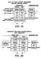
- FIGURE 3C discloses a control panel for implementing a mode described as AUTO UP first detent maintained, manual second detent.
- the switches shown in FIGURE 2C will not accomplish this operation scheme unless the switch is designed to maintain its first toggle position.
- switch 74 will maintain its position at either the AUTO UP with anti trap or AUTO DOWN positions until the driver physically returns the switch to the center OFF position.
- the second detent position discloses a MANUAL UP or MANUAL DOWN and the FIGURE emphasizes that the MANUAL UP position has no anti-trap protection.
- the MANUAL UP and MANUAL DOWN positions comprise second detent positions requiring a higher force to actuate than the AUTO positions.
- FIGURE 3D shows a system where the driver's side toggles are arranged to have a center OFF position, first detents signaling MANUAL DOWN and MANUAL UP, and second detents indicating AUTO DOWN and AUTO UP. Again, the second detents require a higher force to operate than the first detent position.
- a separate anti-trap disable/override switch 84 corresponding to the anti-trap override switch 20 of FIGURE 1 is disposed to conveniently allow the operator to turn ON or OFF the anti-trap protection of MANUAL UP. AUTO UP is disabled when anti-trap is disabled.
- switch 84 could be backlit when the override is on as an easily perceptible indicator to the operator.
- a driver side control panel including an MANUAL UP in a third detent position for anti-trap override is shown. More particularly, toggles 90, 92 are configured to have a center OFF position, an MANUAL DOWN position and a AUTO DOWN position.
- the UP positions comprise MANUAL UP with anti-trap protection, AUTO UP with anti-trap protection and MANUAL UP with no anti-trap protection.
- a "tap" based AUTO UP switch with second detent for anti-trap override is shown.
- the AUTO UP with anti-trap protection can be triggered using the toggle switch of FIGURE 2C by employing a timer so that when the switch 54 is toggled for closing the up contacts for a certain period of time, it can be released by the operator and the window will continue to close with AUTO UP with anti-trap protection.
- the MANUAL UP with anti-trap enabled 96 can be converted to AUTO UP with anti-trap enabled by a tap of the switch 54 for a preselected time interval.
- the toggle 54 To override the anti-trap protection, the toggle 54 must be compressed with a relatively higher force and a longer stroke so that both the up contacts and the down contacts are closed. The logic circuit will thus realize that the driver is indicating that the window should be closed while overriding the anti-trap protection.
- FIGURES 4A-4C a state diagram illustrating the method for implementing the panel switch system of FIGURE 3E is shown therein.
- FIGURE 4A relates to system operation during a window moving down
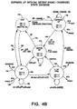
- FIGURE 4B relates to a window moving up
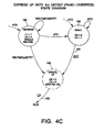
- FIGURE 4C relates to anti-trap or override conditions.
- Idle state 100 will occur after ignition ON and remain until either the up or down toggle contacts are closed by the operator.
- the coil In the idle state, the coil is neither energized for down or up movement ("CD": coil down; "CU”: coil up; "REVTMR”: reverse direction timer). It also will remain idle, as further shown by returning loop 102, when the up contacts are closed if either an anti-trap test, i.e., operability test ("ATT”) has failed or the anti-trap sensor ("ATS”) detects an obstacle.
- ATT operability test
- ATS anti-trap sensor
- EXPRESS DOWN AUTO DOWN
- the system will move to an EXPRESS DOWN TRIGGERED STATE 114 and will return to the EXPRESS DOWN state 120 unless a cancel signal is received.
- the cancel signal is detected by the current sensor due to either a short or stall or a time-out period being sensed or executed by the logic circuit 50. Usually, the window closing will indicate a stall condition being recognized by the current sensor. From the EXPRESS DOWN state 120, the operator can cancel by tapping the up toggle 124 or the down toggle 122 or when a positive cancel signal is sensed 124.
- FIGURE 4B similarly comprises a state diagram illustrating the method of operating for the system when an up signal is received.
- the window can be moved UP at state 130 manually when the operator indicates an up signal 132 and the system senses no obstacle.
- the system will remain in MANUAL UP as per loop 132 until the operator releases the up toggle 134 or until an obstruction is sensed 136 or a panic state is indicated overriding the anti-trap sensor 138 .
- EXPRESS UP TRIGGER is sensed 140
- the system will move into the EXPRESS UP (AUTO UP) state 142 and will remain there until either a cancel 144 or an operator stop signal 146 is sensed.
- the system in either the MANUAL UP state 130, the EXPRESS UP TRIGGER STATE 140 , or the AUTO UP state 142 , the system is in an anti-trap condition so that when an obstacle is sensed by the anti-trap sensor, the window will cease receiving the coil up signal, which will be more fully disclosed with reference to FIGURE 4C. From a CANCEL state 148 , usually being when the window is closed, the system will return to IDLE state 100.
- ATO anti-trap override
Landscapes
- Power-Operated Mechanisms For Wings (AREA)
- Window Of Vehicle (AREA)
Claims (10)
- Ein Steuersystem für ein Automobilfenster einschließlich eines Anti-Einfangschutzes in einer UP bzw. AUF-Betriebsart, wobei folgendes vorgesehen ist:eine motorisierte Antriebsanordnung (12) zum Antreiben des Fensters zwischen einem offenen und einem geschlossenen Zustand;ein Sensor (22) angeordnet zum Detektieren wann ein Objekt zwischen dem Fenster und dem Rahmen vorhanden ist, um ein eine Repräsentation dafür vorsehendes Anti-Einfangsignal zu übertragen;eine Schaltanordnung (16, 18) zur Übertragung von Schaltsignalen die repräsentativ sind für Benutzerbefehle durch Disposition in ausgewählten unterschiedlichen Betriebsarten, Positionen oder Zeitintervalle aufweisend; undeine Logikschaltung (50) angeordnet zum Empfang der Schaltsignale und des Einfangsignals und Steuerung der Antriebsanordnung ansprechend darauf, wobei die Schaltanordnung einen Schalter aufweist, der in die erwähnten unterschiedlichen Betriebsarten bewegbar ist, die folgendes aufweisen: eine OFF- bzw. AUS-Betriebsart, eine Manuell-Abwärts- bzw. MANUAL DOWN Betriebsart, eine AUTO DOWN bzw. Automatisch-Abwärts-Betriebsart, eine AUTO UP- bzw. Automatisch-Aufwärts-Betriebsart mit Anti-Einfangschutz eingeschaltet und gekennzeichnet durch eine einzige MANUAL UP bzw. Von-Hand-AUF-Betriebsart mit abgeschaltetem anti-trap Schutz.
- Steuersystem nach Anspruch 1, wobei die Schaltanordnung erste und zweite körperlich voneinander beabstandete Schalter aufweist, wobei der erste Schalter (60) die AUTO DOWN- bzw. Automatisch-Abwärts-Betriebsart, die OFF- bzw. AUS-Betriebsart und die AUTO-UP bzw. Automatisch-AUF-Betriebsart mit Anti-Einfangschutz eingeschaltet und der zweite Schalter (62) die MANUAL DOWN- bzw. Von-Hand-Abwärts-Betriebsart, die OFF- bzw. AUS-Betriebsart und die MANUAL UP bzw. Von-Hand-Aufwärts-Betriebsart mit Anti-Einfang-Schutz eingeschaltet umfasst.
- Steuersystem nach Anspruch 1, wobei der Schalter Rastpositionen aufweist, die den erwähnten unterschiedlichen Betriebsarten entsprechen, und wobei die AUTO-UP bzw. Automatisch-Auf-Rastung für die AUTO UP- bzw. Automatisch-Auf-Betriebsart mit Anti-Einfangschutz eingeschaltet angeordnet ist zwischen der OFF- bzw. AUS-Rastung für die OFF- bzw. AUS-Position und einer MANUAL UP- bzw. Von-Hand-Auf-Rastung für die MANUAL UP- bzw. Von-Hand-Auf-Position mit Anti-Einfangschutz ausgeschaltet.
- Steuersystem nach Anspruch 3, wobei die MANUAL-UP bzw. Von-Hand-Aufwärts-Rastung eine höhere Benutzerkraft benutzt, um die Betätigung zu erreichen, als die AUTO-UP bzw. Automatisch-Aufwärts-Rast-Position.
- Steuersystem nach Anspruch 4, wobei der Schalter Mittel aufweist, um den Schalter in den AUTO bzw. automatischen Positionen zu halten, bis durch den Benutzer die Rückkehr zu der mittigen OFF- bzw. AUS-Position erfolgt.
- Ein Steuersystem für ein Automobilfenster einschließlich eines Anti-Einfangschutzes in einer UP- bzw. AUF-Betriebsart, wobei folgendes vorgesehen ist:eine motorisierte Antriebsanordnung (12) zum Antreiben des Fensters zwischen offen und geschlossen;einen Sensor (22) angeordnet um ein Objekt zu detektieren das zwischen dem Fenster und dem Rahmen vorhanden ist um sodann ein dafür repräsentatives Anti-Einfangsignal zu übertragen;eine Schalteranordnung (16, 18) zur Verbindung von Schaltersignalen repräsentativ für Benutzerbefehle durch Disposition in ausgewählten unterschiedlichen Betriebsarten die Positionen oder Zeitintervalle aufweisen; undeine Logikschaltung (50) angeordnet zum Empfang der Schaltsignale und des Einfangsignals und zur Steuerung der Antriebsanordnung ansprechend darauf, wobei die Schalteranordnung einen Schalter aufweist, der in die erwähnten unterschiedlichen Betriebsarten schaltbar ist, wobei die unterschiedlichen Betriebsarten folgendes aufweisen:eine OFF- bzw. AUS-Betriebsart, eine MANUAL DOWN- bzw. Von-Hand-Abwärts-Betriebsart, eine AUTO-DOWN bzw. Automatisch-Abwärts-Betriebsart, eine AUTO-UP- bzw. Automatisch-Aufwärtsbetriebsart mit Anti-Einfang eingeschaltet, eine MANUAL-UP- bzw. Von-Hand-AUF-Betriebsart mit Anti-Einfang eingeschaltet, und eine MANUAL-UP bzw. Von-Hand-Aufwärts-Betriebsart mit Anti-Einfangschutz abgeschaltet, dadurch gekennzeichnet, dass der Schalter eine Rastposition für die MANUAL UP- bzw. Von-Hand-Aufwärtsbetriebsart mit Anti-Einfang eingeschaltet und eine Rastposition für AUTO-UP- bzw. Automatisch-Aufwärtsbetriebsart mit Anti-Einfang eingeschaltet aufweist, wobei die erwähnte Schalteranordnung derart strukturiert ist, dass eine Benutzerkraft zur Bewegung des erwähnten Schalters zu der erwähnten Rastung entsprechend der MANUAL UP- bzw. Von-Hand-Aufwärtsbetriebsart mit Anti-Einfang eingeschaltet eine höhere Benutzerbetätigungskraft aufweist, als die Bewegung des Schalters in die erwähnte Rastung entsprechend der AUTO-UP bzw. Automatisch-Aufwärtsbetriebsart mit Anti-Einfang eingeschaltet.
- Steuersystem nach Anspruch 6, wobei die Schaltanordnung beweglich ist aus der MANUAL UP- bzw. Manuell-Aufwärtsbetriebsart, mit Anti-Einfang eingeschaltet in die AUTO-UP bzw. Automatisch-Aufwärtsbetriebsart mit Anti-Einfang eingeschaltet, und zwar durch eine Benutzerbetätigung der Schalteranordnung für ein vorgewähltes Zeitintervall.
- Steuersystem nach Anspruch 6, wobei der Schalter Rastpositionen aufweist entsprechend den unterschiedlichen Betriebsarten, wobei die Rastpositionen eine OFF- bzw. Aus-Rastung, eine erste MANUAL-UP- bzw. Von-Hand-Aufwärtsrastung mit Anti-Einfang eingeschaltet, eine zweite AUTO-UP bzw. Automatisch-Aufwärtsrastung mit Anti-Einfang eingeschaltet und eine dritte MANUAL UP- bzw. Von-Hand-Aufwärtsrastung mit Anti-Einfang eingeschaltet aufweisen.
- Verfahren zum Betrieb einer Schalteranordnung (16, 18) für ein Automobilfenster zur Realisierung einer Übersteuerung eines Anti-Einfangsystems beim Schließen des Fensters, wobei das Verfahren die folgenden Schritte aufweist:Anordnen einer Schalteranordnung (16, 18) mit einer Vielzahl von unterschiedlichen Positionen repräsentativ für einen Benutzer unterschiedlicher Fensteroperationen, wobei folgendes vorgesehen ist:eine OFF- bzw. AUS-Betriebsart, eine erste UP- bzw. Aufwärtsbetriebsart mit Anti-Einfang eingeschaltet und eine zweite "UP" bzw. AUF-Betriebsart mit Anti-Einfang ausgeschaltet,erstes Bewegen des Schalters aus der OFF- bzw. AUS-Position in eine erste UP- bzw. AUF-Rastposition um das Schließen des Fensters einzuleiten, undzweites Bewegen des Schalters aus der ersten UP- bzw. AUF-Rastposition in eine zweite UP- bzw. AUF-Rastposition um das Schließen des Fensters vorzusehen, wobei das Anti-Einfangsystem eingeschaltet ist.
- Verfahren nach Anspruch 9, wobei das zweite Bewegen eine höhere Benutzerbetätigungskraft erfordert als das erste Bewegen.
Applications Claiming Priority (2)
| Application Number | Priority Date | Filing Date | Title |
|---|---|---|---|
| US922586 | 1997-09-03 | ||
| US08/922,586 US5949207A (en) | 1997-09-03 | 1997-09-03 | Auto window switch and obstacle detect/protect with override |
Publications (3)
| Publication Number | Publication Date |
|---|---|
| EP0901210A2 EP0901210A2 (de) | 1999-03-10 |
| EP0901210A3 EP0901210A3 (de) | 1999-09-22 |
| EP0901210B1 true EP0901210B1 (de) | 2002-12-04 |
Family
ID=25447268
Family Applications (1)
| Application Number | Title | Priority Date | Filing Date |
|---|---|---|---|
| EP98116578A Expired - Lifetime EP0901210B1 (de) | 1997-09-03 | 1998-09-02 | Elektrischer Scheibenhebeschalter und Hinderniserkennung/schutz mit vorrangiger Betätigung |
Country Status (3)
| Country | Link |
|---|---|
| US (1) | US5949207A (de) |
| EP (1) | EP0901210B1 (de) |
| DE (1) | DE69809859T2 (de) |
Families Citing this family (24)
| Publication number | Priority date | Publication date | Assignee | Title |
|---|---|---|---|---|
| US6404158B1 (en) * | 1992-04-22 | 2002-06-11 | Nartron Corporation | Collision monitoring system |
| JP3756718B2 (ja) * | 2000-01-17 | 2006-03-15 | アルプス電気株式会社 | 耐水性パワーウインド装置 |
| US6573678B2 (en) * | 2000-03-02 | 2003-06-03 | Siemens Vdo Automotive Corporation | “Express up” vehicle window system and method |
| DE10026126A1 (de) * | 2000-05-26 | 2001-11-29 | Bayerische Motoren Werke Ag | Panikschließsystem und -verfahren |
| US6249732B1 (en) * | 2000-06-16 | 2001-06-19 | Meritor Light Vehicle Technology, Llc | Window characteristic mapping for object detection |
| US7293467B2 (en) * | 2001-07-09 | 2007-11-13 | Nartron Corporation | Anti-entrapment system |
| WO2003063318A1 (es) * | 2001-12-27 | 2003-07-31 | Lear Automotive (Eeds) Spain,S.L. | Metodo de detección de atrapamientos causados por elevalunas motorizados y similares, mediante algoritmos de lósica borrosa |
| US6906487B2 (en) * | 2002-01-21 | 2005-06-14 | International Rectifier Corporation | Anti-pinch window drive circuit |
| US6732476B2 (en) * | 2002-02-12 | 2004-05-11 | The Chamberlain Group, Inc. | Wireless barrier-edge monitor method |
| US6756754B2 (en) | 2002-10-01 | 2004-06-29 | Siemens Vdo Automotive Inc. | Integrated one touch up and down windowlift motor with direct sense for anti-pinch |
| AU2003202807A1 (en) * | 2002-12-17 | 2004-07-09 | Matsushita Electric Industrial Co., Ltd. | Support structure for a pressure sensitive sensor |
| JP3815738B2 (ja) * | 2003-09-08 | 2006-08-30 | 本田技研工業株式会社 | パワーウインドシステム |
| JP2005273421A (ja) * | 2004-03-26 | 2005-10-06 | Honda Motor Co Ltd | パワーウィンドウシステム |
| DE102005016893A1 (de) * | 2004-05-08 | 2006-04-20 | Conti Temic Microelectronic Gmbh | Schaltungsanordnung und Verfahren zur elektrischen Steuerung und/oder Regelung der Bewegung eines elektrisch betriebenen Aggregats |
| US7312591B2 (en) * | 2005-03-11 | 2007-12-25 | Npc Corporation | Powered panel moving system |
| DE202005011044U1 (de) * | 2005-07-06 | 2006-11-16 | Brose Fahrzeugteile Gmbh & Co. Kommanditgesellschaft, Coburg | Sensorsystem für eine Einklemmschutzvorrichtung |
| US7342373B2 (en) * | 2006-01-04 | 2008-03-11 | Nartron Corporation | Vehicle panel control system |
| JP4528264B2 (ja) * | 2006-01-20 | 2010-08-18 | 本田技研工業株式会社 | 車両の開閉パネルシステム |
| US9234979B2 (en) | 2009-12-08 | 2016-01-12 | Magna Closures Inc. | Wide activation angle pinch sensor section |
| US8493081B2 (en) * | 2009-12-08 | 2013-07-23 | Magna Closures Inc. | Wide activation angle pinch sensor section and sensor hook-on attachment principle |
| US9970228B2 (en) * | 2013-10-04 | 2018-05-15 | The Chamberlain Group, Inc. | Movable barrier safety sensor override |
| US10820444B2 (en) * | 2016-08-31 | 2020-10-27 | Commscope Technologies Llc | Systems and methods for monitoring the presence of rack mounted equipment |
| US11643862B2 (en) | 2019-05-14 | 2023-05-09 | Toyota Motor Engineering & Manufacturing North America, Inc. | Sensor module for vehicle cargo door |
| US11894206B2 (en) | 2021-09-30 | 2024-02-06 | Toyota Motor Engineering & Manufacturing North America, Inc. | Controlling automatic operation of a tailgate responsive to an applied load |
Family Cites Families (16)
| Publication number | Priority date | Publication date | Assignee | Title |
|---|---|---|---|---|
| GB9406485D0 (en) * | 1994-03-31 | 1994-05-25 | Standard Prod Ltd | Deformable system |
| CH625605A5 (de) * | 1976-10-02 | 1981-09-30 | Sick Optik Elektronik Erwin | |
| US5329163A (en) * | 1987-08-01 | 1994-07-12 | Toyo Denso Kabushiki Kaisha | Auto-switch for power window |
| US5138182A (en) * | 1988-07-28 | 1992-08-11 | Kabushiki Kaisha Tokai-Rika-Denki-Seisakusho | Apparatus for controlling power window regulator |
| AT391735B (de) * | 1988-09-01 | 1990-11-26 | Mewald Gmbh | Fuehlleiste |
| JPH02136940U (de) * | 1989-04-19 | 1990-11-15 | ||
| US5191268A (en) * | 1991-08-26 | 1993-03-02 | Stanley Home Automation | Continuously monitored supplemental obstruction detector for garage door operator |
| JPH0617068U (ja) * | 1992-08-04 | 1994-03-04 | アルプス電気株式会社 | シーソスイッチ |
| JPH06197592A (ja) * | 1992-12-25 | 1994-07-15 | Tokai Rika Co Ltd | モータ駆動制御装置 |
| DE4432955C2 (de) * | 1993-09-28 | 2002-10-31 | Volkswagen Ag | Verfahren zum Betreiben eines elektromotorischen Fensterscheibenhebers für ein Kraftfahrzeug |
| US5621290A (en) * | 1993-10-18 | 1997-04-15 | Draftex Industries Limited | Movable-window safety device |
| US5510583A (en) * | 1994-03-18 | 1996-04-23 | Eaton Corporation | Assembly for sequential switching |
| US5412297A (en) * | 1994-06-27 | 1995-05-02 | Stanley Home Automation | Monitored radio frequency door edge sensor |
| US5661385A (en) * | 1994-12-19 | 1997-08-26 | The Regents Of The University Of California | Window-closing safety system |
| US5610484A (en) * | 1995-05-04 | 1997-03-11 | Itt Automotive Electrical Systems, Inc. | Auto reverse power closure system |
| US5598918A (en) * | 1995-05-18 | 1997-02-04 | Trw Inc. | Switch for vehicle power window |
-
1997
- 1997-09-03 US US08/922,586 patent/US5949207A/en not_active Expired - Lifetime
-
1998
- 1998-09-02 EP EP98116578A patent/EP0901210B1/de not_active Expired - Lifetime
- 1998-09-02 DE DE69809859T patent/DE69809859T2/de not_active Expired - Fee Related
Also Published As
| Publication number | Publication date |
|---|---|
| EP0901210A3 (de) | 1999-09-22 |
| DE69809859D1 (de) | 2003-01-16 |
| EP0901210A2 (de) | 1999-03-10 |
| US5949207A (en) | 1999-09-07 |
| DE69809859T2 (de) | 2003-11-06 |
Similar Documents
| Publication | Publication Date | Title |
|---|---|---|
| US5949207A (en) | Auto window switch and obstacle detect/protect with override | |
| US5754017A (en) | Power window with detecting function of sticking of foreign matter | |
| US4621223A (en) | Load drive control system for a motor vehicle window | |
| US5592060A (en) | System for sensing an obstruction between a movable panel and a stationary panel frame | |
| US7370905B2 (en) | Door-opening/closing apparatus | |
| US5592777A (en) | Apparatus for interrupting operation of a motor driven movable member upon contacting an obstacle | |
| US4351016A (en) | Device for arresting the motion of a motor driven panel | |
| JP2002525234A (ja) | 自動車の電気的に作動される集合体の動きを電気的に制御及び調節するための方法及び装置 | |
| US6002228A (en) | Device for electronically controlling a motor vehicle displacement mechanism | |
| JPH0799947B2 (ja) | 自動車の電動式開閉部の駆動装置 | |
| US6335602B1 (en) | Squeeze protection system | |
| JP2004143732A (ja) | 開閉体の制御装置 | |
| US6308461B1 (en) | Method and system for detecting an object in the path of an automotive window utilizing a piezoelectric sensor | |
| US5749173A (en) | Power window regulator apparatus | |
| EP1085157A1 (de) | Durch ein Fenster übertragenes Hindernisdetektorsignal | |
| JP2962340B2 (ja) | パワーウインドウ装置 | |
| US20030074840A1 (en) | Vehicular power window safety device | |
| US6601905B1 (en) | Convertible power top and power window switch | |
| EP0506626A1 (de) | Gerät zur Steuerung eines Kraftfahrzeug-Fensterhebers | |
| JP3788934B2 (ja) | 挟み込み検出装置及び車両用バックドア装置 | |
| JP3730523B2 (ja) | 車両用バックドアの挟み込み検出装置 | |
| EP0584033A1 (de) | Einklemmschuitz für Fensterheber und Schiebedächer von Kraftfahrzeugen | |
| KR100439909B1 (ko) | 자동차의 전동식 도어 윈도 레귤레이터용 장애물 감지 기구 | |
| JP3480093B2 (ja) | 車両用開閉体制御装置 | |
| KR960023589A (ko) | 자동차 파워윈도우 고장시 수동에 의한 윈도우 개폐 장치 |
Legal Events
| Date | Code | Title | Description |
|---|---|---|---|
| PUAI | Public reference made under article 153(3) epc to a published international application that has entered the european phase |
Free format text: ORIGINAL CODE: 0009012 |
|
| AK | Designated contracting states |
Kind code of ref document: A2 Designated state(s): DE ES FR GB IT |
|
| AX | Request for extension of the european patent |
Free format text: AL;LT;LV;MK;RO;SI |
|
| PUAL | Search report despatched |
Free format text: ORIGINAL CODE: 0009013 |
|
| AK | Designated contracting states |
Kind code of ref document: A3 Designated state(s): AT BE CH CY DE DK ES FI FR GB GR IE IT LI LU MC NL PT SE |
|
| AX | Request for extension of the european patent |
Free format text: AL;LT;LV;MK;RO;SI |
|
| RIC1 | Information provided on ipc code assigned before grant |
Free format text: 6E 05F 15/00 A, 6H 02H 7/085 B, 6F 16P 3/12 B |
|
| 17P | Request for examination filed |
Effective date: 20000322 |
|
| AKX | Designation fees paid |
Free format text: DE ES FR GB IT |
|
| 17Q | First examination report despatched |
Effective date: 20010430 |
|
| GRAG | Despatch of communication of intention to grant |
Free format text: ORIGINAL CODE: EPIDOS AGRA |
|
| GRAG | Despatch of communication of intention to grant |
Free format text: ORIGINAL CODE: EPIDOS AGRA |
|
| GRAH | Despatch of communication of intention to grant a patent |
Free format text: ORIGINAL CODE: EPIDOS IGRA |
|
| GRAH | Despatch of communication of intention to grant a patent |
Free format text: ORIGINAL CODE: EPIDOS IGRA |
|
| GRAA | (expected) grant |
Free format text: ORIGINAL CODE: 0009210 |
|
| AK | Designated contracting states |
Kind code of ref document: B1 Designated state(s): DE ES FR GB IT |
|
| PG25 | Lapsed in a contracting state [announced via postgrant information from national office to epo] |
Ref country code: IT Free format text: LAPSE BECAUSE OF FAILURE TO SUBMIT A TRANSLATION OF THE DESCRIPTION OR TO PAY THE FEE WITHIN THE PRESCRIBED TIME-LIMIT;WARNING: LAPSES OF ITALIAN PATENTS WITH EFFECTIVE DATE BEFORE 2007 MAY HAVE OCCURRED AT ANY TIME BEFORE 2007. THE CORRECT EFFECTIVE DATE MAY BE DIFFERENT FROM THE ONE RECORDED. Effective date: 20021204 |
|
| REG | Reference to a national code |
Ref country code: GB Ref legal event code: FG4D |
|
| REF | Corresponds to: |
Ref document number: 69809859 Country of ref document: DE Date of ref document: 20030116 |
|
| RAP2 | Party data changed (patent owner data changed or rights of a patent transferred) |
Owner name: DELPHI TECHNOLOGIES, INC. |
|
| PG25 | Lapsed in a contracting state [announced via postgrant information from national office to epo] |
Ref country code: ES Free format text: LAPSE BECAUSE OF FAILURE TO SUBMIT A TRANSLATION OF THE DESCRIPTION OR TO PAY THE FEE WITHIN THE PRESCRIBED TIME-LIMIT Effective date: 20030627 |
|
| ET | Fr: translation filed | ||
| PG25 | Lapsed in a contracting state [announced via postgrant information from national office to epo] |
Ref country code: GB Free format text: LAPSE BECAUSE OF NON-PAYMENT OF DUE FEES Effective date: 20030902 |
|
| PLBE | No opposition filed within time limit |
Free format text: ORIGINAL CODE: 0009261 |
|
| STAA | Information on the status of an ep patent application or granted ep patent |
Free format text: STATUS: NO OPPOSITION FILED WITHIN TIME LIMIT |
|
| 26N | No opposition filed |
Effective date: 20030905 |
|
| GBPC | Gb: european patent ceased through non-payment of renewal fee | ||
| REG | Reference to a national code |
Ref country code: FR Ref legal event code: TP |
|
| PGFP | Annual fee paid to national office [announced via postgrant information from national office to epo] |
Ref country code: FR Payment date: 20050823 Year of fee payment: 8 |
|
| PGFP | Annual fee paid to national office [announced via postgrant information from national office to epo] |
Ref country code: DE Payment date: 20050825 Year of fee payment: 8 |
|
| PG25 | Lapsed in a contracting state [announced via postgrant information from national office to epo] |
Ref country code: DE Free format text: LAPSE BECAUSE OF NON-PAYMENT OF DUE FEES Effective date: 20070403 |
|
| REG | Reference to a national code |
Ref country code: FR Ref legal event code: ST Effective date: 20070531 |
|
| PG25 | Lapsed in a contracting state [announced via postgrant information from national office to epo] |
Ref country code: FR Free format text: LAPSE BECAUSE OF NON-PAYMENT OF DUE FEES Effective date: 20061002 |