EP0901304A2 - Central de télécommunications et terminal d'abonné - Google Patents
Central de télécommunications et terminal d'abonné Download PDFInfo
- Publication number
- EP0901304A2 EP0901304A2 EP98250312A EP98250312A EP0901304A2 EP 0901304 A2 EP0901304 A2 EP 0901304A2 EP 98250312 A EP98250312 A EP 98250312A EP 98250312 A EP98250312 A EP 98250312A EP 0901304 A2 EP0901304 A2 EP 0901304A2
- Authority
- EP
- European Patent Office
- Prior art keywords
- isdn
- interface
- subscriber
- bus
- bit
- Prior art date
- Legal status (The legal status is an assumption and is not a legal conclusion. Google has not performed a legal analysis and makes no representation as to the accuracy of the status listed.)
- Withdrawn
Links
- 230000005540 biological transmission Effects 0.000 claims abstract description 101
- 238000010168 coupling process Methods 0.000 claims abstract description 17
- 238000005859 coupling reaction Methods 0.000 claims abstract description 17
- 239000011159 matrix material Substances 0.000 claims description 16
- 238000011144 upstream manufacturing Methods 0.000 claims 1
- 230000008878 coupling Effects 0.000 abstract description 16
- 230000002093 peripheral effect Effects 0.000 abstract 2
- 238000009434 installation Methods 0.000 abstract 1
- 238000010586 diagram Methods 0.000 description 3
- 230000004913 activation Effects 0.000 description 2
- 102100023817 26S proteasome complex subunit SEM1 Human genes 0.000 description 1
- 208000017547 Ectodermal dysplasia-syndactyly syndrome Diseases 0.000 description 1
- 101000684297 Homo sapiens 26S proteasome complex subunit SEM1 Proteins 0.000 description 1
- 101000873438 Homo sapiens Putative protein SEM1, isoform 2 Proteins 0.000 description 1
- 101000633786 Homo sapiens SLAM family member 6 Proteins 0.000 description 1
- 102100029197 SLAM family member 6 Human genes 0.000 description 1
- 230000008901 benefit Effects 0.000 description 1
- 230000008859 change Effects 0.000 description 1
- 238000006243 chemical reaction Methods 0.000 description 1
- 238000011161 development Methods 0.000 description 1
- 230000018109 developmental process Effects 0.000 description 1
- JEIPFZHSYJVQDO-UHFFFAOYSA-N ferric oxide Chemical compound O=[Fe]O[Fe]=O JEIPFZHSYJVQDO-UHFFFAOYSA-N 0.000 description 1
- 238000009432 framing Methods 0.000 description 1
- 238000005070 sampling Methods 0.000 description 1
- 239000013589 supplement Substances 0.000 description 1
Images


Classifications
-
- H—ELECTRICITY
- H04—ELECTRIC COMMUNICATION TECHNIQUE
- H04Q—SELECTING
- H04Q11/00—Selecting arrangements for multiplex systems
- H04Q11/04—Selecting arrangements for multiplex systems for time-division multiplexing
- H04Q11/0428—Integrated services digital network, i.e. systems for transmission of different types of digitised signals, e.g. speech, data, telecentral, television signals
- H04Q11/0435—Details
- H04Q11/0471—Terminal access circuits
-
- H—ELECTRICITY
- H04—ELECTRIC COMMUNICATION TECHNIQUE
- H04M—TELEPHONIC COMMUNICATION
- H04M1/00—Substation equipment, e.g. for use by subscribers
- H04M1/72—Mobile telephones; Cordless telephones, i.e. devices for establishing wireless links to base stations without route selection
- H04M1/725—Cordless telephones
- H04M1/72502—Cordless telephones with one base station connected to a single line
-
- H—ELECTRICITY
- H04—ELECTRIC COMMUNICATION TECHNIQUE
- H04M—TELEPHONIC COMMUNICATION
- H04M2250/00—Details of telephonic subscriber devices
- H04M2250/08—Details of telephonic subscriber devices home cordless telephone systems using the DECT standard
-
- H—ELECTRICITY
- H04—ELECTRIC COMMUNICATION TECHNIQUE
- H04Q—SELECTING
- H04Q2213/00—Indexing scheme relating to selecting arrangements in general and for multiplex systems
- H04Q2213/1302—Relay switches
-
- H—ELECTRICITY
- H04—ELECTRIC COMMUNICATION TECHNIQUE
- H04Q—SELECTING
- H04Q2213/00—Indexing scheme relating to selecting arrangements in general and for multiplex systems
- H04Q2213/1304—Coordinate switches, crossbar, 4/2 with relays, coupling field
-
- H—ELECTRICITY
- H04—ELECTRIC COMMUNICATION TECHNIQUE
- H04Q—SELECTING
- H04Q2213/00—Indexing scheme relating to selecting arrangements in general and for multiplex systems
- H04Q2213/1305—Software aspects
-
- H—ELECTRICITY
- H04—ELECTRIC COMMUNICATION TECHNIQUE
- H04Q—SELECTING
- H04Q2213/00—Indexing scheme relating to selecting arrangements in general and for multiplex systems
- H04Q2213/13098—Mobile subscriber
-
- H—ELECTRICITY
- H04—ELECTRIC COMMUNICATION TECHNIQUE
- H04Q—SELECTING
- H04Q2213/00—Indexing scheme relating to selecting arrangements in general and for multiplex systems
- H04Q2213/13106—Microprocessor, CPU
-
- H—ELECTRICITY
- H04—ELECTRIC COMMUNICATION TECHNIQUE
- H04Q—SELECTING
- H04Q2213/00—Indexing scheme relating to selecting arrangements in general and for multiplex systems
- H04Q2213/13202—Network termination [NT]
-
- H—ELECTRICITY
- H04—ELECTRIC COMMUNICATION TECHNIQUE
- H04Q—SELECTING
- H04Q2213/00—Indexing scheme relating to selecting arrangements in general and for multiplex systems
- H04Q2213/13204—Protocols
-
- H—ELECTRICITY
- H04—ELECTRIC COMMUNICATION TECHNIQUE
- H04Q—SELECTING
- H04Q2213/00—Indexing scheme relating to selecting arrangements in general and for multiplex systems
- H04Q2213/13209—ISDN
-
- H—ELECTRICITY
- H04—ELECTRIC COMMUNICATION TECHNIQUE
- H04Q—SELECTING
- H04Q2213/00—Indexing scheme relating to selecting arrangements in general and for multiplex systems
- H04Q2213/13216—Code signals, frame structure
-
- H—ELECTRICITY
- H04—ELECTRIC COMMUNICATION TECHNIQUE
- H04Q—SELECTING
- H04Q2213/00—Indexing scheme relating to selecting arrangements in general and for multiplex systems
- H04Q2213/13299—Bus
-
- H—ELECTRICITY
- H04—ELECTRIC COMMUNICATION TECHNIQUE
- H04Q—SELECTING
- H04Q2213/00—Indexing scheme relating to selecting arrangements in general and for multiplex systems
- H04Q2213/13367—Hierarchical multiplexing, add-drop multiplexing
Definitions
- the invention relates to an ISDN telecommunications system according to the preamble of claim 1 and a subscriber terminal according to the preamble of claim 10 Connection to such an ISDN telecommunications system.
- the network termination device In the known ISDN-base terminal is in the user's premises is usually a so-called network termination device (NTBA - n etwork t erminator b asic a ccess) installed, the exchange side, a U having K0 interface and via a conventional 2-wire cable with the relevant local exchange (DIVO - D igital V Intelligence Unit rtsnetz O) is connected.
- the network termination device On the subscriber side, on the other hand, has a So interface and is connected in parallel with up to eight ISDN terminal devices via a 4-wire line, the individual addressing of the individual ISDN terminal devices being determined by an MSN ( m ulti s ubscriber n umber).
- Such an ISDN base connection has two B channels with a transmission capacity of 64 kbit / s each for data transmission and additionally has a D channel with a transmission capacity of 16 kbit / s, which is used to control a protocol for switching data, preferably that standardized EDSS1.
- Such an ISDN base connection can be used physically up to eight ISDN terminals can be connected, however only two of these ISDN devices can be used at the same time operate, since each of the two B channels only the structure a single connection to the network.
- ISDN telecommunication systems which in turn have an S 0 interface and are connected to the network termination device instead of the individual ISDN terminals, are also generally known.
- the known ISDN telecommunication systems On the subscriber side, the known ISDN telecommunication systems also have So interfaces which provide an internal S 0 bus to which standardized ISDN terminals can be connected.
- such telecommunications systems generally also have connection options for operating conventional analog terminals. It is also known to provide a switching module in the ISDN telecommunication system, which enables the connected ISDN terminals to communicate with one another and with the analog terminals without having to set up a connection to the switching center, which is known as in-house operation.
- the known ISDN telecommunications systems enable thus a variety of different comfort or Mediation functions, but do not change the core problem, that on an ISDN base connection because of the small Number of only two B channels, only two end devices at the same time can have a communication link.
- the invention is therefore based on the object, the possibility to create on an ISDN telecommunications system for an internal ISDN base connection more than two end devices to be able to operate actively at the same time.
- the task is based on a known ISDN telecommunications system according to the preamble of claim 1, by those specified in the characterizing part of claim 1
- the invention includes the technical teaching on which Subscriber side of an ISDN telecommunications system bit rate reduced encoding to use over a B channel to be able to establish multiple connections, the data streams originating from the various end devices separated in the B channel in the ISDN telecommunication system and in the 64 kbit / s transmission format of the ISDN standard provided the connection partner not even an internal device with bit rate reduced Coding is.
- the subscriber terminal device points to the connection to the internal S-Bus of the ISDN telecommunications system according to the invention an S interface and has via at least one terminal that corresponds to a bit rate reduced transmission standard work.
- the of data streams going out to the terminal are then indicated by a Coupling field nested in a B channel of the internal S-bus, to handle multiple connections over a B-channel to be able to and thus the effective transmission capacity to increase the B channels.
- S-bus is to be understood here and in the following generally and includes an S 0 bus in the case of an ISDN basic access and an S 2M bus in the case of a primary multiplex connection.
- the subscriber terminal device several terminals, with the switching matrix bit groups arriving from the terminals to one byte merges and this for transmission via the internal S-buses in a B channel.
- the subscriber terminal a DECT radio base station with several cordless telephones, each in accordance with the DECT transmission standard ETS 300 175 with a transmission rate of 32 kbit / s ITU (formerly CCITT) Rec. G.726 work using the voice data at a sampling rate of 4 kSamples / s each in 4-bit format are in the form of nibbles.
- the coupling field in the The subscriber terminal then sets the cordless Nibbles originating from phones each in pairs Bytes according to the ISDN transmission standard.
- the Subscriber terminal equipment several different bit rate reduced Transmission standards and / or in addition to the normal ones ISDN transmission standard according to the ITU recommendation G.711, with the current transmission standard preferred from the ISDN telecommunications system via an identifier is specified, via the internal S-Bus to the subscriber terminal can be transferred.
- Transcoders are provided which implement the various Make transmission standards.
- the switching matrix in the subscriber terminal, the subscriber side couples incoming bit groups then corresponding to the currently set transmission standard in a B channel of the internal S-buses.
- the advantage here is that the transmission rate adapted to the load of the internal S-bus can be.
- the subscriber terminals be set to a transmission rate of 16 kbit / s, what the simultaneous operation of up to six end devices enabled on the internal S-Bus.
- a transfer rate of 32 kbps still allows simultaneous operation of up to four subscriber terminals, while one Transfer rate of 64 kbit / s the operation of a maximum of two Permits subscriber terminals.
- the coupling field described above can for example integrated in software on the hardware platform ISDN processor VNS 80000 from the US manufacturer VLSI implemented that is particularly suitable for this. However, it is it is also possible to use the coupling field specifically for this to develop developing hardware components.
- the ISDN telecommunications system provided the operation of such subscriber terminals with bitrate-reduced encodings.
- the ISDN telecommunications system according to the invention a coupling field in which the bit rates are reduced working devices originating and in Bytes summarized data streams broken down into bit groups become.
- the ISDN telecommunications system a transcoder between the reduced bit rate Transmission standard and the ISDN transmission standard implemented.
- the ISDN telecommunications system the operation of end devices with different bit rate reduced transmission standards.
- the ISDN telecommunications system preferably several transcoders are provided which implement one between the ISDN transmission standard on the one hand and various bit rate reduced transmission standards on the other hand enable.
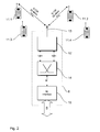
- the system configuration shown in Figure 1 enables the connection of a plurality of terminals on an ISDN-base terminal to a network terminating device (NT - n etwork t erminator b asic a ccess) is provided 1, wherein the network terminating device 1 installed in the premises of the user and trunk side has a U K0 interface, via a conventional 2-wire line to a local exchange (DIVO - D igital V Intelligence Unit rtsnetz O) 2 is connected.
- the local exchange 2 enables the connection to other subscribers and is integrated into the public ISDN network for this purpose.
- the network termination device 1 On the subscriber side, the network termination device 1 has an S 0 interface which is connected via a 4-wire line to an ISDN telecommunications system 3 according to the invention, which is shown in detail in FIG. 3 and will be described in detail.
- the ISDN telecommunication system 3 has at least one further So interface, which provides an internal S 0 bus and enables the connection of the individual subscriber terminals 4, 5, 6 on the subscriber side.
- the ISDN connection units (ISDN-AE) 7, 8, 9 are distributed in the rooms of the user, each of which enables the connection of a subscriber terminal device 4, 5 or 6 and are connected to the internal So bus, the internal S 0 bus is looped through the individual ISDN connection units 7, 8, 9 and is connected at its end to a terminating resistor 10 which prevents line reflections on the internal S 0 bus.
- the subscriber terminal 4 is a conventional ISDN telephone with a data transfer rate of 64 kbit / s according to ITU (formerly CCITT) Rec. G.711 works and therefore only the ISDN transmission standard supported.
- the subscriber terminal 5 is also a telephone, its structure is detailed in the description of FIG. 5 is explained and different from the subscriber terminal 4 by supporting other transmission standards.
- the subscriber terminal 5 thus enables in addition to the usual ISDN transmission rate of 64 kbit / s according to ITU Rec. G.711 also the transmission rate usual for DECT systems of 32 kbit / s according to ITU Rec. G.726 and a transmission standard with a transmission rate of only 16 kbit / s according to ITU Rec. G.726, its use however, to a reduced transmission quality leads.
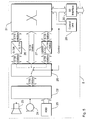
- a DECT radio base station 6 with four cordless telephones 11.1 to 11.4 is connected as the subscriber terminal device, which is shown in detail in FIG. 2 and enables simultaneous operation of two of the cordless telephones 11.1 to 11.4.
- the DECT radio base station 6 has a conventional DECT transceiver station 12 which is connected to an antenna 13 and enables communication with the cordless telephones 11.1 to 11.4 in accordance with the ETSI transmission standard ETS 300175, which has a data transmission rate of 32 kbit / s according to ITU (formerly CCITT) Rec. G.726.
- the DECT radio base station 6 Since the G.711 transmission standard with a data transmission rate of 64 kbit / s is prescribed for ISDN transmission in the public ISDN network, the DECT transceiver 12 cannot be connected directly to the So bus. To adapt the various transmission standards, the DECT radio base station 6 according to the invention therefore has a switching matrix 14 which is connected to the DECT transceiver station 12 and receives the data streams from the respectively active cordless telephones 11.1, 11.2 which correspond to the transmission standard G .726 are coded in 4-bit format with a data transmission rate of 32 kbit / s and thus correspond to half a B channel of the S 0 bus.
- the coupling field 14 combines the 4-bit long nibbles originating from the two active cordless telephones 11.1, 11.2 to form a byte which corresponds to the B-channel format of the ISDN transmission standard G.711.
- the data streams originating from the two cordless telephones 11.1, 11.2 are thus transmitted via a single B channel and thus form "subchannels" in this B channel.
- the DECT radio base station 6 has a So interface 15 which enables the connection to the ISDN connection unit 8 connected to the ISDN telecommunications system 3.
- the ISDN telecommunications system 3 has an S 0 interface 16, which provides the internal S 0 bus and enables the subscriber terminals 4, 5, 6 to be connected.
- the S 0 interface 16 has the task of controlling the data transmission in accordance with the ISDN transmission standard G.711, the So interface 16 transmitting the control data transmitted in the D channel to a control unit 17 which controls the switching-related data transmission.
- the control unit 17 thus evaluates the control data arriving on the D channel and determines from this whether the data coming in on the B channel originate from an ISDN terminal 4, 5 or contain two of the "subchannels" described above, which originate from the terminals 11.1 to 11.4, which work with the bit rate-reduced coding G.726.
- Both the control unit 17 and the one shown in FIG. 2 DECT radio base station 6 have coordinated proprietary extensions of the standardized DSS1 protocol, handling of end devices with "subchanneling" to be able to handle.
- the incoming B-channel data is then fed to a switching matrix 18, which breaks down the individual bytes in the B channel into four-bit long nibbles, so that the two B channels are divided by the switching matrix 18 into four "subchannels", which are coded according to the DECT transmission standard according to G.726.
- the four "subchannels" are then converted by a transcoder 19.1 from the DECT transmission rate according to G.726 to the ISDN transmission rate according to G.711.
- B channels B1, B1 ', B2, B2' appear corresponding to the ISDN transmission rate according to G.711, which are fed to a further coupling field 20, which connects the B channels to two with the network termination device 1 connected S 0 interfaces 21.1, 21.2 or to two terminal adapters a / b 21.3, 21.4, the latter enabling the connection of analog terminals.
- the telecommunication system 3 In addition to the normal ISDN operation with a transmission rate of 64 kbit / s and the above-described operation of terminals with a transmission rate of 32 kbit / s in accordance with the DECT standard, the telecommunication system 3 also enables the operation of terminals with a transmission rate of 16 kBit / s according to ITU-Rec. G.726 work.
- each B channel of the internal S 0 bus together with a subsequent additional bit contains three data triples, which form "subchannels" within the ISDN frame structure, so that a total of six terminals can be operated simultaneously on the internal S 0 bus .
- the coupling field 18 in this case separates the data triples from the individual ISDN bit frames and then leads the total of six "subchannels" to a transcoder 19.2, which is based on the transmission rate of 16 kbit / s according to ITU-Rec. G.726 in the ISDN transmission rate of 64 kbit / s according to ITU-Rec. G.711 implements so that six B-channels B1, B1 ', B1 ", B2, B2' and B2" appear at the office-side connection of the transcoder 19.2, which are also fed to the coupling field 20.
- the switching matrix 20 mediates the four or six B channels present on the subscriber side to the two S 0 interfaces 21.1, 21.2 or to the two terminal adapters a / b 21.3, 21.4, which enable the connection of conventional analog terminals. This operating mode of the telecommunication system is explained in detail below with reference to the description of FIG.
- the coupling field 20 selects the associated B channels at the office-side connection of the transcoder 19.1 and routes them the S 0 interface (s) 21.1 or 21.2 or other internal subscriber interfaces that work in the G.711 format.
- the transcoders 19.1, 19.2 are bypassed and the switching matrix 20 selects the B-channels coming directly from the S 0 interface 16 and forwards them to the S 0 interface 21.1 or 21.2.
- the above description relates to a connection setup that starts from one of the connected terminals 11.1 to 11.4 or 4, 5.
- the control unit 17 uses the D-channel data supplied by the S 0 interface 21.1 to check whether one of the ISDN terminals 4, 5 or one of the cordless telephones 11.1 to 11.4 is to be addressed.
- the coupling field 20 forwards the B-channel data directly to the subscriber-side S 0 interface 16, so that the transcoders 19.1, 19.2 are bypassed.
- the system configuration shown according to the invention enables optional on an internal ISDN base connection pure ISDN operation with a maximum of two at the same time working ISDN terminals 4, 5 each on a B channel or a mixed operation with two cordless Phones 11.1, 11.2 together on one B channel and one ISDN terminal 4 or 5 on the other B channel or one pure bit rate reduced operation with a maximum of four cordless telephones working in-house at the same time 11.1 to 11.4, two of the cordless Telephone 11.1 to 11.4 can be combined on a B channel.
- the operation of up to six End devices with a transmission rate of 16 kbit / s according to ITU Rec. G.726 possible, as below based on the description for Figure 7 is explained.
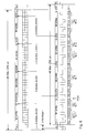
- Figure 4 shows the frame structure of the data transmission the internal So bus of the ISDN telecommunication system 3 in accordance ITU Rec. 430 if both the DECT radio base station 6 with the cordless phones 11.1 and 11.2 as well as the conventional one ISDN telephone 4 are active.
- a frame for transmission from the ISDN telecommunications system 3 to the subscriber terminals 4, 5, 6 is shown, while in the lower area of Figure 4 shows a frame during a transmission from the subscriber terminals 4, 5, 6 to the ISDN telecommunications system 3 is shown.
- the data transfer rate on the internal S 0 bus is 192 kbit / s, the frames each having a length of 48 bits or 250 ⁇ s.
- each of the two cordless telephones 11.1, 11.2 encodes the first logical "0" of a nibble with a negative pulse polarity and each subsequent logical "0" of the same nibble alternately with positive and negative pulse polarity, so that the signal transmitted via the S 0 bus is as DC-free as possible hold.
- the eight bits of the B1 channel are followed by another DC equalization bit L. (D.C. balancing bit), the one DC voltage component of the B1 channel that may occur should compensate.
- the DC equalization bit L. is therefore based on the cordless telephone 11.1 or 11.2 set a logical "0" with positive pulse polarity, if a logical one or three times in the corresponding nibble "0" is present because in this case the nibble is a Contains DC voltage.
- this corresponds to an additional DC voltage offset of around 2%, but this does not result in any particular restrictions given the inaccuracies of around 5% that are present in the symmetrical bus drivers. If necessary, this DC voltage offset can also be compensated for with a higher accuracy of the voltage supply and the line drivers in the end devices. If, on the other hand, only one nibble of the B1 channel contains an odd number of logical zeros, the OR operation leads to a complete compensation of the DC voltage component in the B1 channel when generating the DC voltage compensation bit L.
- D channel bit D a logical one "0" of the D channel bit encoded with negative pulse polarity becomes.
- the following contains DC equalization bit L. a logical "0" with positive Pulse polarity.
- the D-channel bit D with the associated DC voltage compensation bit L then becomes a frame bit F with an associated one DC equalization bit transmitted.
- Either the frame bit F as well as the DC voltage compensation bit L. are from the associated terminal to a logical "0" with negative pulse polarity set to the ISDN telecommunications system 3 successful synchronization to display on the ISDN frame.
- the eight bits of the B2 channel are transmitted generated by the conventional ISDN terminal 4 (TE4) were, the ISDN terminal 4 the first logical "0" within the B2 channel byte with a negative pulse polarity and all subsequent logical zeros within of the entire B2 channel byte alternately with positive and encoded negative pulse polarity, so that a possibly DC component present by the following DC equalization bit L. fully compensated can be.
- TE4 conventional ISDN terminal 4
- the next B1 channel byte then follows within the ISDN frame with two nibbles of the two cordless phones 11.1, 11.2 (TE11.1, TE11.2) followed by a DC equalization bit L. and a D channel bit with the associated DC equalization bit L ..
- ISDN frame in the case of a transmission from the subscriber terminals 4, 5, 6 to the ISDN telecommunications system 3, that compared to that shown in the lower area of FIG. 3 ISDN frame is transferred offset by 2 bits and has a slightly different structure.
- the ISDN frame shown in the upper area of FIG an activation bit A (activation bit), a multi-frame bit M (Multiframing bit), a D-channel echo bit E and a for Bit S provided for study purposes.
- D channel echo bit E gives the content of the previously from the end devices to the ISDN telecommunications system 3 transmitted D-channel bits D again what is indicated by the arrows from the lower frame to the upper frame is indicated.
- FIG. 5 shows the structure of the ISDN telephone shown in FIG. 1 5, which - as already mentioned above - in addition the ISDN transmission standard with a transmission rate of 64 kbit / s according to ITU-Rec. G.711 also transfer rates of 32 kbit / s according to the DECT standard ITU Rec. G.726 and 16 kbit / s supported.
- the core of the telephone 5 is a conventional telephone module 22, which operates according to the DECT standard G.726 with a transmission rate of 32 kbit / s and is connected to a loudspeaker 23, a microphone 24 and a keypad 25 for operation.
- the conversion to the other transmission standards with transmission rates of 64 kbit / s according to ITU-Rec. G.711 or 16 kbit / s according to ITU-Rec. G.726 is carried out by two transcoders 26, 27 which are connected to the telephone module 22 by a signal switch 28, the position of which determines the operating mode of the telephone 5.
- the control of the signal switch 28 for setting the desired operating mode is carried out by a control unit 29 which is connected on the input side to an S 0 interface 30 via which the telephone 5 can be connected to one of the ISDN connection units 7, 8, 9.
- the control unit 29 continuously monitors the D channel of the internal S 0 bus and checks whether the ISDN telecommunication system 3 transmits an identifier which determines the desired operating mode. In this case, the control unit 29 sends a corresponding signal to the signal switch 28, whereupon the telephone module 22 is connected to the associated transcoder 26 or 27 or is directly connected to a switching matrix 31.
- the coupling field 31 has on the one hand the task of that Telephone module 22 data coming in the above to couple the described ISDN frame structure. On the other hand disassembles the switching matrix 31 in the case of incoming subscribers Data the individual ISDN frames and separated the data intended for the telephone module 22, which is then isolated be fed to the telephone module 22.
- the functioning of the telephone 5 is first in the operating mode with the transmission standard according to ITU-Rec. G.711 with a transmission rate of 64 kbit / s.
- the data streams emanating from the telephone module 22 are routed from the signal switch 28 to the transcoder 26, which converts the data streams into the ISDN transmission standard in accordance with ITU-Rec. G.711 transformed with a transmission rate of 64 kbit / s.
- the data streams transformed in this way are then fed to the switching matrix 31, which couples the individual bytes into the B1 channel or into the B2 channel of the internal S 0 bus, the choice of the B channel being specified by the ISDN telecommunications system 3 and by the control unit 29 is set.
- the telephone 5 works in the DECT transmission standard according to ITU-Rec. G.726 with a transmission rate of 32 kbit / s, the data streams emanating from the telephone module 22 are fed directly to the coupling field 31, which couples the individual nibbles into the B1 channel or the B2 channel of the internal S 0 bus.
- the ISDN telecommunications system 3 uses a corresponding identifier to specify the B channel into which the telephone 5 couples the data and the position of the nibbles within the ISDN frame structure.
- the telephone 5 has a transmission rate of 16 kbit / s according to the ITU-Rec transmission standard. G.726 is working, the telephone module 22 coming data supplied to the transcoder 27 by the Transmission rate 32 kbit / s in the desired transmission rate of 16 kbit / s. Then the on data streams implemented in this way then the coupling field 31st fed that the individual data triplet in the ISDN frame structure couples in, the control unit 29 accordingly one from the ISDN telecommunications system 3 received identifier specifies in which B-channel and on which Place the data triplet within the B-channel become.
- Figure 6 shows the frame structure for data transmission on the internal S 0 bus when the phone 5 in DECT mode according to ITU-Rec. G.726 works with a transmission rate of 32 kbit / s and in addition the cordless telephone 11.1 and the conventional ISDN telephone 4 are active.
- the nibbles of the cordless telephone 11.1 TE11.1 each occupy the first nibble in the bytes of the B1 channel, while the second nibble in the bytes of the B1 channel each use the telephone 5 (TE5 ) is occupied.
- the B2 channel is then available to the conventional ISDN telephone 4 (TE4) alone.
- the individual nibbles of the B channels can therefore not only be allocated to a subscriber terminal device with several terminals, as shown in FIG. 4, but it is also possible to allocate the nibbles of a B channel directly to different terminals.
- FIG. 7 finally shows the ISDN frame structure for data transmission on the internal S 0 bus for the case already mentioned that six of the telephones 5 shown in FIG. 5 are simultaneously active on the internal So bus, with all telephones TE1, .. ., TE6 with the reduced transmission rate of 16 kbit / s according to ITU-Rec. G.726 work to enable simultaneous transmission of six connections via the S 0 bus.
- the outgoing from the individual terminals TE1, ..., TE6 Data streams are in the form of 3-bit triples coupled into the ISDN frame structure, with in each triplet contains only the first two bits of information while the third bit is a DC equalization bit L. is.
- the first logical "0" of a triple is coded with a negative pulse polarity, while a possibly existing second logical "0" with a positive pulse polarity is encoded to the resulting Keep the signal as free of DC voltage as possible. If a triple contains a logical "1" or twice twice a logical "0", so the two contain information Bits of the triple free of DC voltage, while at only a logic "0" the DC equalization bit L. set to logic "0" with a positive pulse polarity must be to keep the signal free of DC voltage.
- the first triple of the first terminal TE1 takes the first three bits of the B1 channel, while bits four to six of the B1 channel from the first triple of the second terminal TE2 are occupied.
- the third terminal TE3 occupies then with his first triple bits seven and eight of B1 channel and the DC voltage compensation bit L ..
- everyone B-channel is therefore the associated DC voltage compensation bit supplements and contains three triples each, whereby the classification of the individual triples in the ISDN frame structure from the ISDN telecommunications system 3 by one Identifier is specified. This way you can a So bus six connections with a reduced data transfer rate of 16 kbit / s, which is at least sufficient for communication in in-house operation.
- the invention is not limited in its execution the preferred embodiments given above. Rather, a number of variants are conceivable, which fundamentally different from the solution shown makes use of any type.
Landscapes
- Engineering & Computer Science (AREA)
- Computer Networks & Wireless Communication (AREA)
- Signal Processing (AREA)
- Telephonic Communication Services (AREA)
Applications Claiming Priority (4)
| Application Number | Priority Date | Filing Date | Title |
|---|---|---|---|
| DE19739701A DE19739701A1 (de) | 1997-09-04 | 1997-09-04 | ISDN-Telekommunikationsanlage und Teilnehmerendeinrichtung |
| DE19739701 | 1997-09-04 | ||
| DE19739516 | 1997-09-09 | ||
| DE19739516A DE19739516A1 (de) | 1997-09-04 | 1997-09-09 | ISDN-Telekommunikationsanlage und Teilnehmerendeinrichtung |
Publications (1)
| Publication Number | Publication Date |
|---|---|
| EP0901304A2 true EP0901304A2 (fr) | 1999-03-10 |
Family
ID=26039809
Family Applications (1)
| Application Number | Title | Priority Date | Filing Date |
|---|---|---|---|
| EP98250312A Withdrawn EP0901304A2 (fr) | 1997-09-04 | 1998-09-04 | Central de télécommunications et terminal d'abonné |
Country Status (2)
| Country | Link |
|---|---|
| EP (1) | EP0901304A2 (fr) |
| DE (1) | DE19739516A1 (fr) |
Family Cites Families (6)
| Publication number | Priority date | Publication date | Assignee | Title |
|---|---|---|---|---|
| DE3316492A1 (de) * | 1983-05-05 | 1984-11-08 | Siemens AG, 1000 Berlin und 8000 München | Schaltungsanordnung fuer den teilnehmeranschluss in einem diensteintegrierenden digitalnetz (isdn) |
| US5398249A (en) * | 1992-05-14 | 1995-03-14 | Industrial Technology Research Institute | System for providing simultaneous multiple circuit-switched type communications on an ISDN basic rate interface |
| DE4309847C2 (de) * | 1993-03-26 | 1996-11-14 | Siemens Ag | ISDN-Kommunikationssystem |
| DE4309848C2 (de) * | 1993-03-26 | 1997-06-12 | Siemens Ag | Kommunikationssystem zum Anschluß an eine Basisstation eines mehrzellularen, drahtlosen Fernsprechsystems |
| DK0668706T3 (da) * | 1994-01-27 | 1999-11-01 | Siemens Schweiz Ag | Netafslutningsenhed |
| DE19538527A1 (de) * | 1995-10-06 | 1997-04-10 | Elmeg Kommunikationstech | Netzabschlußgerät für eine ISDN - Telekommunikationsanlage |
-
1997
- 1997-09-09 DE DE19739516A patent/DE19739516A1/de not_active Ceased
-
1998
- 1998-09-04 EP EP98250312A patent/EP0901304A2/fr not_active Withdrawn
Also Published As
| Publication number | Publication date |
|---|---|
| DE19739516A1 (de) | 1999-05-20 |
Similar Documents
| Publication | Publication Date | Title |
|---|---|---|
| EP0731618B1 (fr) | Procédé pour commander un réseau d'accès et central avec un tel réseau d'accès | |
| EP0408024B1 (fr) | Groupe de connexion universel de ligne d'abonné RNIS | |
| EP0668706B1 (fr) | Terminal de réseau | |
| DE69126402T2 (de) | Kommunikationssystem mit ISDN-Signalisierung | |
| DE69117108T2 (de) | Teilnehmeranschlusseinheit mit autonomer Leitungsweglenkung für ein Fernmeldenetz mit intelligenter Struktur | |
| DE69434646T2 (de) | Netz mit digitalen und analogen Ausgängen | |
| DE3689115T2 (de) | Übertragungseinrichtung. | |
| EP0971549B1 (fr) | Méthode pour informer les abonnés mobiles des caractéristiques des services sur un réseau de communication | |
| EP0687402B1 (fr) | Circuit permettant d'integrer des systemes informatiques dans le cadre de l'utilisation d'installations telephoniques | |
| DE69213065T2 (de) | ISDN-Analog-Zwischeneinheit | |
| DE69329845T2 (de) | Kommunikationssystem und Nebenstellenanlage dafür | |
| DE3425720A1 (de) | Verfahren zur herstellung von internverbindungen zwischen zwei in busstruktur installierten endgeraeten desselben teilnehmers eines dienstintegrierten digitalen nachrichtennetzes | |
| EP0734186B1 (fr) | Procédé pour commander un réseau d'accès ainsi qu'un réseau d'accès et un central pour cela | |
| DE3851150T2 (de) | Verfahren zur verarbeitung von anrufen. | |
| EP0939536B1 (fr) | Méthode et appareil pour délivrer des services pour des abonnés mobiles par un réseau de communication | |
| EP0691796B1 (fr) | Dispositif de terminaison de réseau | |
| EP1305957B1 (fr) | Systeme permettant de connecter un dispositif de telecommunication a un reseau de communication a commutation de paquets | |
| DE3233221A1 (de) | Schaltungsanordnung zum uebertragen von signalen zwischen teilnehmeranschlussleitungen und wenigstens einer uebertragungsleitung einer dienstintegrierten fernmeldeanlage | |
| EP0127138A2 (fr) | Système de télécommunication relié à un système de traitement d'informations | |
| EP0901304A2 (fr) | Central de télécommunications et terminal d'abonné | |
| DE19953868A1 (de) | Telekommunikationssystem | |
| EP0901303A2 (fr) | Central de télécommunications et terminal d'abonné | |
| EP0477627B1 (fr) | Procédé pour connecter des terminaux de communication dans les réseaux de commutation à services integrés | |
| DE19817007C2 (de) | Verfahren zur Nutzung digitaler Datennetze zum Zwecke der Bandbreitenreduktion bei der Übertragung von Daten über Sprachverbindungswege | |
| EP0901305A2 (fr) | Central de télécommunications RNIS et terminal d'abonné |
Legal Events
| Date | Code | Title | Description |
|---|---|---|---|
| PUAI | Public reference made under article 153(3) epc to a published international application that has entered the european phase |
Free format text: ORIGINAL CODE: 0009012 |
|
| AK | Designated contracting states |
Kind code of ref document: A2 Designated state(s): AT BE CH CY DE DK ES FI FR GB GR IE IT LI LU MC NL PT SE |
|
| AX | Request for extension of the european patent |
Free format text: AL;LT;LV;MK;RO;SI |
|
| STAA | Information on the status of an ep patent application or granted ep patent |
Free format text: STATUS: THE APPLICATION IS DEEMED TO BE WITHDRAWN |
|
| 18D | Application deemed to be withdrawn |
Effective date: 20040331 |