EP0901305A2 - Central de télécommunications RNIS et terminal d'abonné - Google Patents
Central de télécommunications RNIS et terminal d'abonné Download PDFInfo
- Publication number
- EP0901305A2 EP0901305A2 EP98250313A EP98250313A EP0901305A2 EP 0901305 A2 EP0901305 A2 EP 0901305A2 EP 98250313 A EP98250313 A EP 98250313A EP 98250313 A EP98250313 A EP 98250313A EP 0901305 A2 EP0901305 A2 EP 0901305A2
- Authority
- EP
- European Patent Office
- Prior art keywords
- isdn
- data
- channel
- subscriber
- interface
- Prior art date
- Legal status (The legal status is an assumption and is not a legal conclusion. Google has not performed a legal analysis and makes no representation as to the accuracy of the status listed.)
- Withdrawn
Links
- 230000015654 memory Effects 0.000 claims abstract description 20
- 230000008878 coupling Effects 0.000 claims abstract description 12
- 238000010168 coupling process Methods 0.000 claims abstract description 12
- 238000005859 coupling reaction Methods 0.000 claims abstract description 12
- 230000005540 biological transmission Effects 0.000 claims description 50
- 239000000872 buffer Substances 0.000 claims description 20
- 239000011159 matrix material Substances 0.000 claims description 14
- 230000006399 behavior Effects 0.000 claims 1
- 238000006243 chemical reaction Methods 0.000 abstract description 4
- 238000009434 installation Methods 0.000 abstract 2
- 238000010586 diagram Methods 0.000 description 3
- 101000633786 Homo sapiens SLAM family member 6 Proteins 0.000 description 2
- 102100029197 SLAM family member 6 Human genes 0.000 description 2
- 238000011156 evaluation Methods 0.000 description 2
- 230000006870 function Effects 0.000 description 2
- 230000033764 rhythmic process Effects 0.000 description 2
- 102100023817 26S proteasome complex subunit SEM1 Human genes 0.000 description 1
- 101000684297 Homo sapiens 26S proteasome complex subunit SEM1 Proteins 0.000 description 1
- 101000873438 Homo sapiens Putative protein SEM1, isoform 2 Proteins 0.000 description 1
- 238000005352 clarification Methods 0.000 description 1
- 238000004891 communication Methods 0.000 description 1
- 238000011161 development Methods 0.000 description 1
- 230000018109 developmental process Effects 0.000 description 1
- 238000009432 framing Methods 0.000 description 1
- 238000005070 sampling Methods 0.000 description 1
- 230000002123 temporal effect Effects 0.000 description 1
Images


Classifications
-
- H—ELECTRICITY
- H04—ELECTRIC COMMUNICATION TECHNIQUE
- H04M—TELEPHONIC COMMUNICATION
- H04M1/00—Substation equipment, e.g. for use by subscribers
- H04M1/72—Mobile telephones; Cordless telephones, i.e. devices for establishing wireless links to base stations without route selection
- H04M1/725—Cordless telephones
- H04M1/72502—Cordless telephones with one base station connected to a single line
-
- H—ELECTRICITY
- H04—ELECTRIC COMMUNICATION TECHNIQUE
- H04Q—SELECTING
- H04Q11/00—Selecting arrangements for multiplex systems
- H04Q11/04—Selecting arrangements for multiplex systems for time-division multiplexing
- H04Q11/0428—Integrated services digital network, i.e. systems for transmission of different types of digitised signals, e.g. speech, data, telecentral, television signals
- H04Q11/0435—Details
- H04Q11/0471—Terminal access circuits
-
- H—ELECTRICITY
- H04—ELECTRIC COMMUNICATION TECHNIQUE
- H04M—TELEPHONIC COMMUNICATION
- H04M2250/00—Details of telephonic subscriber devices
- H04M2250/08—Details of telephonic subscriber devices home cordless telephone systems using the DECT standard
-
- H—ELECTRICITY
- H04—ELECTRIC COMMUNICATION TECHNIQUE
- H04Q—SELECTING
- H04Q2213/00—Indexing scheme relating to selecting arrangements in general and for multiplex systems
- H04Q2213/1302—Relay switches
-
- H—ELECTRICITY
- H04—ELECTRIC COMMUNICATION TECHNIQUE
- H04Q—SELECTING
- H04Q2213/00—Indexing scheme relating to selecting arrangements in general and for multiplex systems
- H04Q2213/1304—Coordinate switches, crossbar, 4/2 with relays, coupling field
-
- H—ELECTRICITY
- H04—ELECTRIC COMMUNICATION TECHNIQUE
- H04Q—SELECTING
- H04Q2213/00—Indexing scheme relating to selecting arrangements in general and for multiplex systems
- H04Q2213/1305—Software aspects
-
- H—ELECTRICITY
- H04—ELECTRIC COMMUNICATION TECHNIQUE
- H04Q—SELECTING
- H04Q2213/00—Indexing scheme relating to selecting arrangements in general and for multiplex systems
- H04Q2213/13098—Mobile subscriber
-
- H—ELECTRICITY
- H04—ELECTRIC COMMUNICATION TECHNIQUE
- H04Q—SELECTING
- H04Q2213/00—Indexing scheme relating to selecting arrangements in general and for multiplex systems
- H04Q2213/13106—Microprocessor, CPU
-
- H—ELECTRICITY
- H04—ELECTRIC COMMUNICATION TECHNIQUE
- H04Q—SELECTING
- H04Q2213/00—Indexing scheme relating to selecting arrangements in general and for multiplex systems
- H04Q2213/13202—Network termination [NT]
-
- H—ELECTRICITY
- H04—ELECTRIC COMMUNICATION TECHNIQUE
- H04Q—SELECTING
- H04Q2213/00—Indexing scheme relating to selecting arrangements in general and for multiplex systems
- H04Q2213/13204—Protocols
-
- H—ELECTRICITY
- H04—ELECTRIC COMMUNICATION TECHNIQUE
- H04Q—SELECTING
- H04Q2213/00—Indexing scheme relating to selecting arrangements in general and for multiplex systems
- H04Q2213/13209—ISDN
-
- H—ELECTRICITY
- H04—ELECTRIC COMMUNICATION TECHNIQUE
- H04Q—SELECTING
- H04Q2213/00—Indexing scheme relating to selecting arrangements in general and for multiplex systems
- H04Q2213/13216—Code signals, frame structure
-
- H—ELECTRICITY
- H04—ELECTRIC COMMUNICATION TECHNIQUE
- H04Q—SELECTING
- H04Q2213/00—Indexing scheme relating to selecting arrangements in general and for multiplex systems
- H04Q2213/13299—Bus
-
- H—ELECTRICITY
- H04—ELECTRIC COMMUNICATION TECHNIQUE
- H04Q—SELECTING
- H04Q2213/00—Indexing scheme relating to selecting arrangements in general and for multiplex systems
- H04Q2213/13367—Hierarchical multiplexing, add-drop multiplexing
Definitions
- the invention relates to an ISDN telecommunications system and a subscriber terminal for connection to a such ISDN telecommunications system.
- This ISDN telecommunication system enables the operation of several ISDN terminals on one ISDN base connection.
- the ISDN telecommunications system is connected via a 4-wire line to the S 0 interface of a network termination device (NTBA - network terminator basic access), which is installed in the user's room and provides the ISDN basic connection.
- NTBA network termination device
- this network termination device On the office side, this network termination device has a U K0 interface and is connected to the relevant local exchange (DIVO - digital local exchange) via a conventional 2-wire line.
- DIVO - digital local exchange relevant local exchange
- the ISDN telecommunications system also has an S 0 interface to which several ISDN terminals can be connected via 4-wire lines.
- such an ISDN telecommunications system offers a variety of convenience and operator functions, such as internal connections between those connected to the ISDN telecommunications system End devices without a fee-based connection to have to build up to the local exchange.
- the ISDN telecommunications system enables the simultaneous operation of more than two ISDN terminals despite the restriction by only two B channels on the internal S 0 bus.
- bit rate-reduced coding is used on the internal S 0 bus by nesting several data words of the end devices into the individual data words of the B channels.
- each data word in the ISDN transmission standard with a transmission rate of 64 kBit / s contains eight bits, while, for example, the transmission standard DECT with cordless telephones with a transmission rate of 32 kBit / s only provides 4 bits (nibble) in each data word that the data words of two DECT terminals can be nested in a data word of a B channel.
- the data streams originating from the terminal devices operating at reduced bit rates and combined in bytes are then broken down again into the original bit groups and then converted by a transcoder into the ISDN transmission standard with a transmission rate of 64 kbit / s.
- the disadvantage here is that so-called DC balancing errors can occur on the internal S 0 bus, ie the transmission is not free of DC voltage.
- the freedom from DC data transmission on the internal S 0 bus is achieved by using a pseudo-ternary code that encodes a logic one with a zero level and a logic zero when it first occurs with a pulse of negative polarity and then with pulses of alternating polarity.
- the data word is therefore free of DC voltage.
- there is an overhang pulse with negative polarity which is compensated by a subsequent DC balancing bit with positive polarity, so that the data transmission is DC-free even in this case.
- the two nibbles of a data word on the B channel can, however, originate from different terminals, the first logical zero being coded in each nibble with a pulse of negative polarity. If both nibbles now contain an odd number of logic zeros, the entire data word contains two overhang pulses with negative polarity, only one of which can be compensated for by the subsequent DC voltage compensation bit, so that the data transmission is not DC-free in this case.
- the DC voltage component on the internal S 0 bus is therefore due to the fact that the bit rate reduced terminals independently encode the first logical zero of the nibble assigned to them on the B channel with a pulse of negative polarity, which in the case of odd numbers of logical zeros in both nibbles leads to two overhang impulses.
- the invention is therefore based on the object of providing an ISDN telecommunications system of the type described at the outset and terminal devices which operate at a reduced bit rate, in which the data transmission on the internal S 0 -Bis in any case free of DC voltage.
- the task is based on an ISDN telecommunications system according to the preamble of claim 1, by the characterizing features of claim 1 or with respect the correspondingly adapted subscriber terminal solved by the features of claim 6.
- the invention includes the technical teaching of coupling several successive data words of the same terminal into the individual data words of the B channels on the internal S 0 bus instead of the data words of different terminal devices operating at reduced bit rates.
- the first two nibbles of the first terminal are coupled into the first byte of the Bl channel within an S 0 frame of 48 bits.
- Two consecutive nibbles of the third terminal are then coupled into the first B2 channel byte of the S 0 frame.
- the second byte of the B1 channel then contains two successive nibbles of the second terminal and the second byte of the B2 channel within the S 0 frame finally contains two nibbles of the fourth terminal.
- the individual terminals can also occupy the bytes within an S 0 frame in a different order. The only important thing is that a byte contains only the data of one end device.
- this joint coupling of a plurality of temporally successive bit groups of the same terminal into a data word of a B channel advantageously ensures a DC voltage-free data transmission on the internal So bus.
- a buffer memory is therefore provided both in the ISDN telecommunications system according to the invention and in the subscriber terminal device according to the invention, which stores a bit group when sending data via the internal S 0 bus until the next bit group arrives.
- These two successive bit groups are then coupled together through a switching matrix in the terminal or in the telecommunication system into a B channel of the internal S 0 bus. Accordingly, when receiving data via the internal S 0 bus, the buffer memory is used for the temporary storage of a complete data word of a B channel, the individual bit groups being read from the buffer memory by the end devices in the correct chronological rhythm.
- two ISDN data frames each with a length of 48 bits or 250 ⁇ s, are combined to form a superframe with a length of 96 bits or 500 ⁇ s.
- end devices with a reduced transmission rate of 16 kbit / s are used, the data of the end devices present in bit pairs being coupled into the B channels of the internal S 0 bus.
- Each of the eight bytes of the superframe contains four bit pairs of a terminal, so that a total of eight bit rate-reduced terminals can be operated simultaneously on the internal S 0 bus.
- the invention was explained above in connection with an ISDN base connection which provides an S 0 bus with two B channels with a transmission rate of 64 kbit / s each and a D channel for control purposes with a transmission rate of 16 kbit / s .
- the invention can be implemented in the same way with an ISDN primary multiplex connection or with corresponding digital interfaces.
- the invention is not based on the coupling of each two nibbles are limited to one data word of a B channel. Rather, it is also possible to have more than two successive ones Bit groups of a terminal in a data word of a B channel. So at a data transfer rate of 8 kbit / s, for example four consecutive pairs of bits in a byte of a B channel be coupled.
- the coupling field described above can for example integrated in software on the hardware platform ISDN processor VNS 80000 from the US manufacturer VLSI implemented that is particularly suitable for this. However, it is it is also possible to use the coupling field specifically for this to develop developing hardware components.
- the system configuration shown in Figure 1 enables the connection of a plurality of terminals on an ISDN-base terminal to a network termination device (NTBA - network t erminator b asic a ccess) is provided 1, wherein the network terminating device 1 is installed in the premises of the user, and trunk side has a Uko interface, via a conventional 2-wire line to a local exchange (DIVO - D igital V Intelligence Unit rtsnetz O) 2 is connected.
- the local exchange 2 enables the connection to other subscribers and is integrated into the public ISDN network for this purpose.
- the network termination device 1 On the subscriber side, the network termination device 1 has an S 0 interface which is connected via a 4-wire line to an ISDN telecommunications system 3 according to the invention, which is shown in detail in FIG. 3 and will be described in detail.
- the ISDN telecommunication system 3 has at least one further S 0 interface which provides an internal S 0 bus and enables the connection of the individual subscriber terminals 4, 5, 6 on the subscriber side .
- S 0 interface S 0 interface
- several ISDN connection units (ISDN-AE) 7, 8, 9 are arranged in the user's rooms, each of which enables the connection of a subscriber terminal 4, 5 or 6 and are connected to the internal S 0 bus
- the internal S 0 bus is looped through the individual ISDN connection units 7, 8, 9 and is connected at its end to a terminating resistor 10 which prevents line reflections on the internal S 0 bus.
- the subscriber terminals 4, 5 are ISDN telephones that use both the ISDN transmission standard a data transfer rate of 64 kbit / s according to ITU (formerly CCITT) Rec. G.711 as well as the DECT transmission standard according to ITU Rec. G.711 with a transmission rate of 32 kbit / s support.
- ITU formerly CCITT
- DECT DECT transmission standard
- a DECT radio base station is also used as the subscriber terminal 6 with four cordless phones 11.1 to 11.4 connected, which is shown in detail in Figure 2 and simultaneous operation of two of the cordless ones Allows phones 11.1 to 11.4.
- the DECT radio base station points to this 6 a conventional DECT transceiver station 12, which is connected to an antenna 13 and communication with the cordless phones 11.1 to 11.4 according to the transmission standard set by ETSI ETS 300175 enables a data transfer rate from 32 kbit / s according to ITU (formerly CCITT) Rec.G.726 provides.
- the active cordless telephones 11.1, 11.2 transmit data to the ISDN telecommunications system 3 via the internal S 0 bus.
- the DECT transmitting / receiving station 12 delivers bit groups with four bits (English nibbles) at regular time intervals, which are initially buffered in a buffer memory 14.1 or 14.2 in order to subsequently enable a common transmission of two successive nibbles.
- the buffer memory 14.1 serves to receive the nibbles originating from the cordless telephone 11.1, while the buffer memory 14.2 buffers the nibbles of the telephone 11.2.
- each data word on a B channel of the internal S 0 bus thus contains only the nibbles of a terminal 11.1 or 11.2. This is important for the subsequent coding in accordance with the ISDN transmission standard G.711 with a data transmission rate of 64 kbit / s, which is carried out by a downstream S 0 interface 16.
- a pseudo-ternary code is used in accordance with the ISDN transmission standard, which encodes a logical one with a zero level and a logical zero when it first occurs with a pulse of negative polarity and then with pulses of alternating polarity.
- the data word is therefore free of DC voltage.
- there is an overhang pulse with negative polarity which is compensated by a subsequent DC balancing bit with positive polarity, so that the data transmission on the internal S 0 bus also in is DC-free in this case.
- a B-channel offers the advantage that the above described coding of logical zeros with changing Polarities within the entire data word can be held so that a maximum of one overhang pulse with negative polarity, which can be caused by the subsequent DC voltage compensation bit compensated becomes.
- this coding rule can be violated because the two nibbles of a data word on a B channel of different End devices, which are the first logical Zero within its nibble independently with negative Encode polarity.
- the active cordless telephones 11.1, 11.2 receive data from the ISDN telecommunication system 3 via the internal S 0 bus. It is assumed here that the data intended for the telephone 11.1 are contained within an S 0 frame in the first byte of the B1 channel, while the data intended for the telephone 11.2 are each transmitted with the first byte of the B2 channel, such as is also shown in Figure 4.
- the S 0 interface 16 then passes these two bytes on receipt of an S 0 frame to the coupling fields 15.1, 15.2, which each break the bytes down into two nibbles, which are stored in parallel in the buffer memories 14.1, 14.2.
- the two nibbles are then successively pushed out of the buffer memories 14.1, 14.2 and passed on to the DECT transceiver station 12, the stored nibbles being released periodically in order to equalize the time of the jointly transmitted nibbles.
- the DECT radio base station 6 therefore has a control device which is not shown here for the sake of simplicity and which controls the buffer memories 14.1, 14.2 accordingly.
- the ISDN telecommunications system 3 has an S 0 interface 17 which provides the internal S 0 bus and enables the subscriber terminals 4, 5, 6 to be connected.
- the S 0 interface 17 has the task of controlling the data transmission on the internal S 0 bus in accordance with the ISDN transmission standard G.711, the S 0 interface 17 transmitting the control data transmitted in the D channel to a control unit 18 , which controls the switching data transmission.
- the control unit 18 thus evaluates the control data arriving on the D-channel at the subscriber end and determines from this whether the data coming in on the B-channel originate from an ISDN terminal or contain two of the "subchannels" described above, which are provided by the terminals 11.1 to 11.4 or the phones 4, 5, which work with the bit rate-reduced coding G.726. Furthermore, the ISDN telecommunications system has two further S 0 interfaces 19.1, 19.2, which enable connection to a network termination device 1.
- Both the control unit 18 and the one shown in FIG. 2 DECT radio base station 6 have coordinated proprietary extensions of the standardized DSS1 protocol, handling of end devices with "subchanneling" to be able to handle.
- the B-channel data arriving on the subscriber side are then fed to a switching matrix 20, which is controlled by the control unit 18 and is connected to a further switching matrix 21 arranged on the office side.
- the switching matrix 20 forwards the incoming B-channel data to the exchange switching point 21 if the B-channel data originate from an ISDN terminal, since in this case no further conversion is required.
- the exchange switch 21 on the office side forwards the incoming B-channel data directly to the switch 20 on the subscriber side if a conventional ISDN terminal is addressed on the internal S 0 bus, since no conversion is required in this case either.
- the switching matrix 20 forwards the B-channel data arriving on the subscriber side to two switching matrixes 22.1, 22.2, which each break down the bytes of the B-channels into two nibbles. Each of these nibbles represents the data supplied by one of the terminals 11.1, 11.2, 4, 5 at two successive times.
- the two nibbles are then temporarily stored in a buffer memory 23.1, 23.2 and then pushed out of the buffer memory 23.1, 23.2 in a predetermined time sequence and fed to a transcoder 24.1, 24.2, which is based on the subscriber-side transmission standard according to ITU-Rec. G.726 with a transmission rate of 32 kbit / s in the ISDN transmission standard according to ITU-Rec. G.711 implemented with a transmission rate of 64 kbit / s. It is important here that the nibbles are pushed out of the buffer memory 23.1, 23.2 at a predetermined time interval of 125 microseconds, which corresponds to half a S 0 frame. In this way, a time equalization is achieved and the original time sequence of the nibbles is restored.
- the switching matrix 21 routes the incoming B-channel data to the two transcoders 24.1, 24.2 an implementation of the ISDN transmission standard according to ITU-Rec. G.711 with a transmission rate of 64 kbit / s in the DECT transmission standard according to ITU-Rec. G.726 with a Carry out a transmission rate of 32 kbit / s.
- the B-channel data converted in this way and present in the form of nibbles are then written successively into a buffer memory 23.1, 23.2, the content of which can be read out in parallel by the switching matrix 22.1, 22.2.
- the switching matrix 22.1, 22.2 therefore reads two successive nibbles from the buffer memory 23.1, 23.2 and combines them into a byte, which is then fed to the switching matrix 20 and coupled into a B channel of the internal S 0 bus.
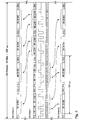
- FIG. 4 shows the frame structure during data transmission from the DECT terminals 11.1, 11.2, 4, 5 to the ISDN telecommunications system 3, the frame structure being shown on the internal S 0 bus in the center of the picture, while the frame structure is shown at the top and bottom the external S 0 buses between the ISDN telecommunications system 3 and the network termination device 1 is reproduced.
- frames with a length of 48 bits are transmitted via the S 0 bus, which in addition to control information contain two bytes of the B1 channel and two bytes of the B2 channel.
- F fraing bit
- L DC voltage compensation bit
- the first byte of the B1 channel contains two nibbles that were generated by the cordless telephone 11.1.
- the first byte of the Bl channel is followed by a further DC voltage compensation bit L.
- DC balancing bit which is intended to compensate for a DC voltage component of the Bl channel that may occur.
- the DC voltage compensation bit L. is therefore set to a logic "0" with positive pulse polarity if an odd number of logic zeros occurs in the associated byte, since in this case the byte contains a DC voltage component.
- D channel bit D a logical one "0" of the D channel bit encoded with negative pulse polarity becomes.
- the following contains DC equalization bit L. a logical "0" with positive Pulse polarity.
- the next B1 channel byte then follows within the ISDN frame with two nibbles from the one working in DECT mode ISDN telephone 4 were generated, followed by one DC equalization bit L. and a D-channel bit with the associated DC voltage compensation bit L ..
- next B2 channel byte follows with two Nibbles from the one that also works in DECT mode ISDN telephone 5 originate.
- the second byte of the B2 channel is again followed by a DC equalization bit L. a possibly existing DC voltage component of this byte compensated.
- FIG. 4 also shows how the ISDN telecommunications system 3 according to the invention Frame structure converted to despite the subscriber side Operation of DECT terminals 4, 5, 11.1, 11.2 on the office side to enable a connection with conventional ISDN terminals.
- the first byte of the B1 channel contains two nibbles of the cordless telephone 11.1, which were generated one after the other in time. These two nibbles are from the transcoder 24.1 of the transmission standard according to ITU-Rec. G.726 with a transmission rate of 32 kbit / s in the ISDN transmission standard according to ITU-Rec. G.711 implemented with a transmission rate of 64 kbit / s and then form two complete bytes, which are coupled into an S 0 frame of the external S 0 interface 19.2, as the curved arrows in FIG. 4 illustrate. The byte resulting from the first nibble is coupled into the first byte of the B1 channel within an S 0 frame of the external S 0 interface 19.2, while the byte resulting from the second nibble forms the second byte of the B1 channel.
- the first byte of the B2 channel of the internal S 0 bus contains two nibbles that were generated in succession by the cordless telephone 11.2. These nibbles are implemented by the transcoder 24.2 and then form two complete bytes which are coupled into the two bytes of the B2 channel at the external S 0 interface 19.2 with a time delay.
- the second byte of the Bl channel of the internal S 0 bus comes from the telephone 4 working in DECT mode.
- This byte also contains two nibbles, which correspond to successive sampling times and each form a complete byte after being implemented by the transcoder 24.1 .
- These bytes are then coupled into the two bytes of the B1 channel at the external S 0 interface 19.1, as can be seen from the curved arrows.
- the second byte of the B2 channel of the internal S 0 bus contains two nibbles which originate from the telephone 5 operating in DECT mode. These two nibbles are in turn converted by the transcoder 24.2 into complete bytes and then coupled into the two bytes of the B2 channel at the external S 0 interface 19.1.
- FIG. 5a shows the frame structure described above for clarification in a clearer representation, from which it can be seen that each byte of a B channel only the data of a telecommunications terminal TE1, TE2, TE3 or TE4 contains, where the data of the telecommunication terminals are in the form of nibbles.
- FIG. 5b shows a further possible frame structure in which two ISDN frames, each with a length of 48 bits or 250 ⁇ s, are combined to form a superframe with a length of 96 bits or 500 ⁇ s.
- the terminals work with a bit rate reduction at a transmission rate of 16 kbit / s, so that the data of the individual terminals TE1 TE8 are available in the form of bit pairs.
- Each B-channel byte thus contains four bit pairs of a terminal, so that a maximum of eight terminals can be operated simultaneously on the internal S 0 bus.
- the invention is not limited in its execution the preferred embodiments given above. Rather, a number of variants are conceivable, which fundamentally different from the solution shown makes use of any type.
Landscapes
- Engineering & Computer Science (AREA)
- Computer Networks & Wireless Communication (AREA)
- Signal Processing (AREA)
- Telephonic Communication Services (AREA)
Applications Claiming Priority (6)
| Application Number | Priority Date | Filing Date | Title |
|---|---|---|---|
| DE19739701A DE19739701A1 (de) | 1997-09-04 | 1997-09-04 | ISDN-Telekommunikationsanlage und Teilnehmerendeinrichtung |
| DE19739701 | 1997-09-04 | ||
| DE19739516 | 1997-09-09 | ||
| DE19739516A DE19739516A1 (de) | 1997-09-04 | 1997-09-09 | ISDN-Telekommunikationsanlage und Teilnehmerendeinrichtung |
| DE19746721 | 1997-10-14 | ||
| DE19746721A DE19746721A1 (de) | 1997-09-09 | 1997-10-14 | ISDN-Telekommunikationsanlage und Teilnehmerendeinrichtung |
Publications (1)
| Publication Number | Publication Date |
|---|---|
| EP0901305A2 true EP0901305A2 (fr) | 1999-03-10 |
Family
ID=27217730
Family Applications (1)
| Application Number | Title | Priority Date | Filing Date |
|---|---|---|---|
| EP98250313A Withdrawn EP0901305A2 (fr) | 1997-09-04 | 1998-09-04 | Central de télécommunications RNIS et terminal d'abonné |
Country Status (1)
| Country | Link |
|---|---|
| EP (1) | EP0901305A2 (fr) |
-
1998
- 1998-09-04 EP EP98250313A patent/EP0901305A2/fr not_active Withdrawn
Similar Documents
| Publication | Publication Date | Title |
|---|---|---|
| EP0408024B1 (fr) | Groupe de connexion universel de ligne d'abonné RNIS | |
| EP0668706B1 (fr) | Terminal de réseau | |
| DE69329845T2 (de) | Kommunikationssystem und Nebenstellenanlage dafür | |
| DE3425720C2 (fr) | ||
| EP0998078A1 (fr) | Méthode pour la configuration d'une liaison de communication pour transmission de données | |
| DE2856897C1 (de) | Digitale Zeitmultiplex-Vermittlungsanordnung | |
| EP0901305A2 (fr) | Central de télécommunications RNIS et terminal d'abonné | |
| EP0127138A2 (fr) | Système de télécommunication relié à un système de traitement d'informations | |
| EP0359156A2 (fr) | Interface d'un réseau et terminal téléphonique | |
| DE19746721A1 (de) | ISDN-Telekommunikationsanlage und Teilnehmerendeinrichtung | |
| EP0638221B1 (fr) | Méthode d'établissement de liaisons de données dans une installation de postes secondaires de communication | |
| EP0111114A2 (fr) | Montage pour une centrale téléphonique, en particulier une centrale téléphonique privée avec communication additionnelle de données | |
| EP0126482B1 (fr) | Système de télécommunication à la fois pour trafic en mode-circuit et pour trafic en mode-paquet | |
| EP0673179B1 (fr) | Terminal de réseau de télécommunication | |
| DE3240999A1 (de) | Schaltungsanordnung fuer eine fernsprechvermittlungsanlage, insbesondere fernsprechnebenstellenanlage mit zusaetzlichem datenverkehr | |
| DE3309888C2 (de) | Verfahren zur gleichzeitigen Realisierung einer Fernsprech- und einer Datenverbindung, insbesondere Bildschirmtextverbindung, vorzugsweise in Fernsprechnebenstellenanlagen | |
| DE4141725A1 (de) | Verfahren zum uebertragen nachrichtentechnischer signale | |
| EP0901303A2 (fr) | Central de télécommunications et terminal d'abonné | |
| EP0901304A2 (fr) | Central de télécommunications et terminal d'abonné | |
| EP0963134B1 (fr) | Méthode de transmission de données utilisateur dans un réseau numérique à intégration de services (RNIS) | |
| DE4000098A1 (de) | Uebertragungseinrichtung mit einem isdn-bus | |
| DE3028155A1 (de) | Digitaler teilnehmeranschluss fuer fernsprechen einschliesslich text- und datendienste | |
| DE3238086C2 (fr) | ||
| DE3539039C2 (fr) | ||
| EP1033847A2 (fr) | Procédé pour le choix d'un réseau de télécommunication pour la transmission d'information entre deux terminaux ainsi qu'un routeur pour la mise en oeuvre |
Legal Events
| Date | Code | Title | Description |
|---|---|---|---|
| PUAI | Public reference made under article 153(3) epc to a published international application that has entered the european phase |
Free format text: ORIGINAL CODE: 0009012 |
|
| AK | Designated contracting states |
Kind code of ref document: A2 Designated state(s): AT BE CH CY DE DK ES FI FR GB GR IE IT LI LU MC NL PT SE |
|
| AX | Request for extension of the european patent |
Free format text: AL;LT;LV;MK;RO;SI |
|
| STAA | Information on the status of an ep patent application or granted ep patent |
Free format text: STATUS: THE APPLICATION IS DEEMED TO BE WITHDRAWN |
|
| 18D | Application deemed to be withdrawn |
Effective date: 20050401 |