EP0901428B1 - Betätigungsvorrichtung für eine hebekonstruktion mit zwei spindeln, jede mit einer spindelmutter - Google Patents
Betätigungsvorrichtung für eine hebekonstruktion mit zwei spindeln, jede mit einer spindelmutter Download PDFInfo
- Publication number
- EP0901428B1 EP0901428B1 EP97926062A EP97926062A EP0901428B1 EP 0901428 B1 EP0901428 B1 EP 0901428B1 EP 97926062 A EP97926062 A EP 97926062A EP 97926062 A EP97926062 A EP 97926062A EP 0901428 B1 EP0901428 B1 EP 0901428B1
- Authority
- EP
- European Patent Office
- Prior art keywords
- control device
- hydraulic
- fork
- nut
- shunt
- Prior art date
- Legal status (The legal status is an assumption and is not a legal conclusion. Google has not performed a legal analysis and makes no representation as to the accuracy of the status listed.)
- Expired - Lifetime
Links
- 239000012530 fluid Substances 0.000 claims abstract description 6
- 238000006073 displacement reaction Methods 0.000 claims description 9
- 238000005259 measurement Methods 0.000 claims 1
- 230000001105 regulatory effect Effects 0.000 abstract 1
- 230000000750 progressive effect Effects 0.000 description 4
- 230000008901 benefit Effects 0.000 description 3
- 238000001514 detection method Methods 0.000 description 3
- 230000005540 biological transmission Effects 0.000 description 2
- 230000000903 blocking effect Effects 0.000 description 2
- 230000008878 coupling Effects 0.000 description 2
- 238000010168 coupling process Methods 0.000 description 2
- 238000005859 coupling reaction Methods 0.000 description 2
- 238000005096 rolling process Methods 0.000 description 2
- 230000001360 synchronised effect Effects 0.000 description 2
- 230000002159 abnormal effect Effects 0.000 description 1
- 230000000295 complement effect Effects 0.000 description 1
- 238000010276 construction Methods 0.000 description 1
- 230000007547 defect Effects 0.000 description 1
- 238000010586 diagram Methods 0.000 description 1
- 239000013536 elastomeric material Substances 0.000 description 1
- 230000006698 induction Effects 0.000 description 1
- 238000009434 installation Methods 0.000 description 1
- 239000002184 metal Substances 0.000 description 1
- 230000001960 triggered effect Effects 0.000 description 1
Images
Classifications
-
- B—PERFORMING OPERATIONS; TRANSPORTING
- B60—VEHICLES IN GENERAL
- B60P—VEHICLES ADAPTED FOR LOAD TRANSPORTATION OR TO TRANSPORT, TO CARRY, OR TO COMPRISE SPECIAL LOADS OR OBJECTS
- B60P1/00—Vehicles predominantly for transporting loads and modified to facilitate loading, consolidating the load, or unloading
- B60P1/44—Vehicles predominantly for transporting loads and modified to facilitate loading, consolidating the load, or unloading having a loading platform thereon raising the load to the level of the load-transporting element
-
- B—PERFORMING OPERATIONS; TRANSPORTING
- B60—VEHICLES IN GENERAL
- B60P—VEHICLES ADAPTED FOR LOAD TRANSPORTATION OR TO TRANSPORT, TO CARRY, OR TO COMPRISE SPECIAL LOADS OR OBJECTS
- B60P3/00—Vehicles adapted to transport, to carry or to comprise special loads or objects
- B60P3/06—Vehicles adapted to transport, to carry or to comprise special loads or objects for carrying vehicles
- B60P3/08—Multilevel-deck construction carrying vehicles
Definitions
- the present invention relates to a device for operating a supporting structure in lifting-lowering or push-pull especially for a vehicle carrier road unit.
- the lifting post screws used in couples especially for the transport of cars loaded on platforms or trays carried by these screws are conventionally controlled by one or several mechanical, electric or motor energy hydraulic mounted between the posts or at the base of a post of each couple.
- DE 31 47 591 A shows the Characteristics of the preamble of claim 1.
- the screws of the support posts preferably four in number powered by a single motor for the four posts or a motor specific to each couple.
- this link makes the volume located under and between the posts.
- the mechanical drive causes a significant noise which can represent noise pollution, especially at night during maneuvers lifting and lowering.
- the object of the present invention is to remedy to these different disadvantages.
- the problem solved by the invention is that of a smaller footprint, a silent and vibration-free drive and a better mechanical efficiency, and greater reliability all this at a lower cost compared to previous solutions.
- the invention relates to a device for operating a supporting structure in lifting-lowering or push-pull especially for a vehicle carrier road unit, device formed of a couple of screws each carrying a nut of translation prisoner inside a fork moving along each post a couple of posts, characterized in that the screws have each a high stop and a low stop and a reference position indicator or detector, screws also each having one of their ends a hydraulic motor, the motors hydraulics being supplied in series from a same pressure source and each shunted by a bypass each comprising a hydraulic member of bypass with automatic opening or controlled for make the bypass passable for the fluid hydraulic especially in the case of a stop or a blocking of the corresponding hydraulic motor.
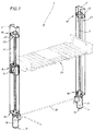
- the invention is consists of a couple 1 of two lifting poles 2,3 vertical, inclined or horizontal, bearing and each containing a driving screw 4.5 preferably suspended, on each of which is mounted a nut translation 6.7 connected to a fork 8.9 serving as cage.
- the forks 8.9 preferably comprise each two side pads 10,11 for their sliding movement along the posts whose longitudinal interior edges such as 12.13 their serve as a guide.
- Each of the screws on each post is rotated by a hydraulic motor 14,15 to engine block 16,17 provided at one of the lower ends 18 or high 19 of the screws, in the extension of the body linear of these.
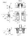
- the 4.5 screws are mounted in the posts by one of their ends via a thrust bearing 20, for example with balls.
- This thrust bearing 20 or the motor 14.15 when in the high position is mounted on elastic blocks such as 21 in connection with a support piece 22 serving as a high stop 23 with interposition of an elastic intermediate piece 24.
- Each fork 8.9 constitutes the interface between each travel nut 6.7 and a structure any link, preferably a structure carrier such as that referenced by 25 on the Figure 1 which can be of the plate, platform or other of different shape less extensive or localized supporting a load, for example carried by a unit road transport vehicle.
- a structure carrier such as that referenced by 25 on the Figure 1 which can be of the plate, platform or other of different shape less extensive or localized supporting a load, for example carried by a unit road transport vehicle.
- the screws 4.5 are mounted in such a way way they are suspended at amortization omnidirectional elastic at one end and guided with an axial clearance at the other end, by example by an end shaped like a splined shaft on which is mounted a grooved sleeve 26 of coupling engaging with a drive element hydraulic motor.
- post (x) the metal structure (s) carrying at least by one end and protecting the screws. He must be well understood that we will use this term throughout description without any desire to limit for designate both vertical screws and screws horizontal or inclined. So no limitation particular with regard to the inclination and the screw position should not be sought in this term.
- the supporting structure is maintained and made reclining by links adapted for example to pivot pins 27.28 projecting from the forks 8.9 bearing for example a roller or a pad 29.30 and by suitable means provided along the structure carrier 25.
- Each lifting motor screw 4,5 is driven directly by a hydraulic motor 14,15 whose engine blocks 16,17 are housed in the lower part or high posts in line with the screws lifting.
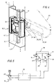
- Hydraulic motors 14,15 are supplied from the same source 33 of hydraulic fluid under pressure, for example a pump driven by a M engine or PTO or other generator fluid under pressure, through a control member single distributor circuit input or other common to both engines.
- Hydraulic power to engines 14.15 is carried out by a series connection, i.e. loop, through a single conduit from the source of pressure 33 with return to the cover 34 through a general control unit, for example a distributor 35.
- the connection between the motors is therefore carried out by a simple supply conduit 36. According to the invention, this is the only link existing between the two engines.
- the motors 14,15 are each shunted by a hydraulic bypass 37,38 including a member hydraulic bypass 39.40 opening either automatic, for example a pressure limiter, or triggered in total, partial opening or progressive by an external command, for example a solenoid valve or any other hydraulic component equivalent.
- the opening can be ordered by a trigger from the physical detection of a reference position marked by an indicator. She can also be ordered by comparison in continuous of a quantity representative of the position instantaneous via a physical quantity variable reaching a setpoint representative of the reference position.
- Hydraulic bypass components 39.40 can be pressure relief valves produced for example in the form of tared non-return valves or any other component of equivalent function, i.e. with automatic opening under certain pressure / flow conditions.
- Nut 6.7 is kept floating with functional games in the following way in the fork 8.9 serving as a cage.
- each nut is in contact with the top of the fork cage crossed by the screw by a piece 41 of elastomeric material.
- the elastic connection with the fork cage can be held mechanically by an internal cage.
- This elastic piece 41 for connecting or contact prevents jamming and therefore sudden blockage nut in the cage and reduces wear by better bearing of the nut on the screw. The bouncing and vibrations are dampened or even deleted.
- the screw is suspended by its upper end in the support piece 22 serving as a high stop 23 to using the elastic block 21 allowing it a certain axial play.
- each screw 4,5 is driven directly by its hydraulic motor 14,15 which is mounted in its extension.
- this end is shaped according to a grooved axis which engages by the grooved union sleeve 26 in a complementary training room constituting the mechanical output of the hydraulic motor.
- the coupling of mechanical drive can also be achieved through a joint homokinetic.
- Engine shutdown is controlled by a detector which activates in total, partial opening or progressive hydraulic bypass member during approaching or when crossing the reference position. The other engine will continue to drive the corresponding screw until catching the opposite fork position.
- the reference positions can be materialized by intermediate stops under the form of a fixed or movable part but always retractable.
- the reference position function can also be filled by a position detector, proximity or passing or by comparison with a setpoint.
- the part forming a stop can be replaced by a detector placed on the the travel nut 6.7 or the fork 8.9 which will carry a detectable element. It can also be the opposite, i.e. a detector placed in the travel nut or in the fork.
- the number of screw turns constitutes information on the position of the travel nut. This information can be used to order the opening of the bypass member placed in the bypass at when the number of screw turns corresponding to the stop position is reached.
- Typical operation with physical stop position is characterized in that the nut which arrives first in reference position stop contact will cause the corresponding motor to lock up. In because of the bypass at the motor terminals, this high internal resistance of the motor will force the limiter opening pressure making the bypass busy. This opening will cause through the bypass and through the connecting conduit between the motors resulting from series connection supply direct from the other motor which, continuing to rotate, will bring the second fork to the point stop reference.
- the driver will readjust the horizontality of the tray by letting go the supporting structure in position of reference. It will then bring it back to the desired position for the desired use. He can for example the let go up to the high limit stop 23 where the transverse horizontal defect will be corrected automatically in the case of realization with pressure limiter.
Landscapes
- Engineering & Computer Science (AREA)
- Transportation (AREA)
- Mechanical Engineering (AREA)
- Health & Medical Sciences (AREA)
- Public Health (AREA)
- Forklifts And Lifting Vehicles (AREA)
- Transmission Devices (AREA)
- Support Of The Bearing (AREA)
- Types And Forms Of Lifts (AREA)
- Forms Removed On Construction Sites Or Auxiliary Members Thereof (AREA)
- Shafts, Cranks, Connecting Bars, And Related Bearings (AREA)
Claims (17)
- Betätigungsvorrichtung für eine heb- und senkbare oder mit Zug und Druck arbeitenden Tragstruktur, insbesondere für eine Straßenfahrzeugtransporteinheit, die von einem Paar von Spindeln (4, 5) gebildet ist, von denen jede eine Spindelmutter (6, 7) aufnimmt, die in einer entlang einer Stütze eines Paars von Stützen verschiebbaren Gabel (8, 9) eingeschlossen ist, und die an einem ihrer Enden jeweils von einem Hydraulikmotor (16, 17) angetrieben sind, die beide von einer gemeinsamen Druckflüssigkeitsquelle in Reihe gespeist sind, dadurch gekennzeichnet, daß jeder Hydraulikmotor (16, 17) durch eine Abzweigleitung (37, 38) mit einem hydraulischen, gesteuert oder automatisch öffnenden Bauglied überbrückt ist, um einen Durchfluß durch die Abzweigleitung zu ermöglichen und so die Versorgung dieses Hydraulikmotors (16, 17) mit der Druckflüssigkeit gesteuert oder automatisch teilweise oder vollständig kurzzuschließen, daß die Werte einer die momentane Position jeder Spindelmutter (6, 7) einer jeden Spindel bezüglich einer Bezugsposition, die durch einen für diese Bezugsposition repräsentativen Wert einer physikalischen Größe festgelegt ist, repräsentierenden physikalischen Größe kontinuierlich, meßbar sind, und daß diese Werte mittels eines Komparators verglichen werden, um einen Versatz zwischen der momentanen Position der beiden Spindelmuttern feststellen zu können und -im Falle eines Vorauseilens einer Mutter- den Vorschub dieser Mutter, deren hydraulischer Antriebsmotor kurzgeschlossen ist, durch Einwirken auf die Steuerung des in die Abzweigleitung zum Kurzschließen eingesetzten hydraulischen Bauglieds zumindest so lange zu steuern, bis der Versatz zwischen den beiden Hydraulikmotoren aufgehoben ist.
- Betätigungsvorrichtung nach Anspruch 1, dadurch gekennzeichnet, daß die kontinuierliche Überwachung der Position der beiden Spindelmuttern (6, 7) während des Absenkens und des Anhebens durch einstellbares Verzögern des vorauseilenden Hydraulikmotors bewirkt ist.
- Betätigungsvorrichtung nach dem vorangehenden Anspruch, dadurch gekennzeichnet, daß der vorauseilende Motor durch variables Öffnen des in der Abzweigleitung angeordneten hydraulischen Bauglieds einstellbar verzögerbar ist.
- Betätigungsvorrichtung nach Anspruch 2 oder 3, dadurch gekennzeichnet, daß das gesteuert öffnende hydraulische Bauglied ein einfaches oder elektrisch gesteuertes Ventil ist.
- Betätigungsvorrichtung nach dem vorangehenden Anspruch, dadurch gekennzeichnet, daß das Ventil ein Steuerventil ist.
- Betätigungsvorrichtung nach Anspruch 1, dadurch gekennzeichnet, daß die Bezugsposition wenigstens eine obere oder untere Anschlagposition am Ende des Wegs der Gabel oder der Spindelmutter (6, 7) ist.
- Betätigungsvorrichtung nach Anspruch 1, dadurch gekennzeichnet, daß die Bezugsposition eine Zwischenposition ist.
- Betätigungsvorrichtung nach Anspruch 1, dadurch gekennzeichnet, daß das automatisch öffnende hydraulische Bauglied ein Druckbegrenzungsventil ist.
- Betätigungsvorrichtung nach dem vorangehenden Anspruch, dadurch gekennzeichnet, daß das Druckbegrenzungsventil ein Rückschlagventil ist.
- Betätigungsvorrichtung nach Anspruch 1, dadurch gekennzeichnet, daß das hydraulische Bauglied der Abzweigleitung während des Verschiebens der Gabel (8, 9) in Richtung des Anschlags am oberen oder unteren Ende des Hubs öffnungsgesteuert ist.
- Betätigungsvorrichtung nach Anspruch 1, dadurch gekennzeichnet, daß die das hydraulische Bauglied der Abzweigleitung auf Öffnen gesteuert wird, wenn der Durchlauf der Gabel (8, 9) mittels eines Bezugspositionsgebers detektiert wird.
- Betätigungsvorrichtung nach Anspruch 1, dadurch gekennzeichnet, daß jede Spindelmutter (6, 7) über eine nachgiebige Verbindung in die Gabel (8, 9) eingesetzt ist.
- Betätigungsvorrichtung nach Anspruch 1, dadurch gekennzeichnet, daß die Spindeln (4, 5) horizontal oder geringfügig geneigt sind.
- Betätigungsvorrichtung nach Anspruch 1, dadurch gekennzeichnet, daß die Bezugsposition von einem Anzeiger vorgegeben ist.
- Betätigungsvorrichtung nach dem vorangehenden Anspruch, dadurch gekennzeichnet, daß die Bezugsposition durch eine Umdrehungszahl der Spindel vorgegeben ist.
- Betätigungsvorrichtung nach Anspruch 1, dadurch gekennzeichnet, daß jede Spindelmutter (6, 7) oder jede Gabel (8, 9) mit einem Positionsgeber ausgestattet ist, und daß ein bezüglich dieses Positionsgebers empfindlicher Sensor an der Bewegungsbahn der Spindelmutter oder der Gabel angeordnet ist.
- Betätigungsvorrichtung nach Anspruch 16, dadurch gekennzeichnet, daß der Sensor ein Näherungssensor ist.
Applications Claiming Priority (3)
| Application Number | Priority Date | Filing Date | Title |
|---|---|---|---|
| FR9607253 | 1996-06-07 | ||
| FR9607253A FR2749630B1 (fr) | 1996-06-07 | 1996-06-07 | Dispositif de manoeuvre d'une structure porteuse a partir d'un couple de vis portant chacune un ecrou de translation |
| PCT/FR1997/000945 WO1997047494A1 (fr) | 1996-06-07 | 1997-05-30 | Dispositif de manoeuvre d'une structure porteuse a partir d'un couple de vis portant chacune un ecrou de translation |
Publications (2)
| Publication Number | Publication Date |
|---|---|
| EP0901428A1 EP0901428A1 (de) | 1999-03-17 |
| EP0901428B1 true EP0901428B1 (de) | 2000-08-02 |
Family
ID=9492951
Family Applications (1)
| Application Number | Title | Priority Date | Filing Date |
|---|---|---|---|
| EP97926062A Expired - Lifetime EP0901428B1 (de) | 1996-06-07 | 1997-05-30 | Betätigungsvorrichtung für eine hebekonstruktion mit zwei spindeln, jede mit einer spindelmutter |
Country Status (12)
| Country | Link |
|---|---|
| US (1) | US5938382A (de) |
| EP (1) | EP0901428B1 (de) |
| KR (1) | KR20000016409A (de) |
| CN (1) | CN1094846C (de) |
| AT (1) | ATE195101T1 (de) |
| CA (1) | CA2206150A1 (de) |
| DE (1) | DE69702711T2 (de) |
| DK (1) | DK0901428T3 (de) |
| ES (1) | ES2150260T3 (de) |
| FR (1) | FR2749630B1 (de) |
| PT (1) | PT901428E (de) |
| WO (1) | WO1997047494A1 (de) |
Families Citing this family (43)
| Publication number | Priority date | Publication date | Assignee | Title |
|---|---|---|---|---|
| GB0021813D0 (en) * | 2000-09-06 | 2000-10-18 | Ross & Bonnyman Eng Ltd | Lifting apparatus |
| US6575678B2 (en) | 2000-10-26 | 2003-06-10 | Cottrell, Inc. | Locking cylinder |
| PT1334006E (pt) * | 2000-11-15 | 2011-03-17 | Mark James Long | Veículo de transporte de carga |
| US6491484B2 (en) * | 2000-12-18 | 2002-12-10 | Masao Kubota | Multipurpose freight vehicle |
| GB0030985D0 (en) * | 2000-12-20 | 2001-01-31 | Ross & Bonnyman Eng Ltd | Apparatus and method |
| US7377362B2 (en) * | 2002-12-02 | 2008-05-27 | Rbw Industries, Inc. | Lift system |
| US6983979B2 (en) | 2003-07-31 | 2006-01-10 | Happijac Company | System for moving beds |
| US7025547B2 (en) | 2004-03-29 | 2006-04-11 | Boydstun Metal Works, Inc. | Vehicle transporter with screw actuators |
| US7570062B2 (en) * | 2004-12-10 | 2009-08-04 | Eaton Corporation | Method of actuating a test function of an electrical switching apparatus and electrical switching apparatus employing the same |
| US7114897B1 (en) | 2005-05-25 | 2006-10-03 | Boydstun Metal Works, Inc. | Vehicle support and retention system for a vehicle transporter |
| DE102005050733A1 (de) * | 2005-10-22 | 2007-04-26 | Jungheinrich Ag | Hubmast für Stapler |
| US20070170006A1 (en) * | 2005-11-22 | 2007-07-26 | Hiwin Technologies Corp. | Screw drive mechanism for an elevator |
| DE102006006301B4 (de) * | 2006-02-10 | 2013-03-07 | Hiwin Technologies Corp. | Aufhängung einer Gewindespindel |
| US8100626B2 (en) * | 2006-03-20 | 2012-01-24 | Moti Shai | Versatile powered linear drive utility machine |
| US7575402B2 (en) | 2006-07-06 | 2009-08-18 | Toyota Motor Credit Corporation | Vehicle transporter with screw actuators |
| US20080179142A1 (en) * | 2007-01-27 | 2008-07-31 | Yung-Tsai Chuo | Torque Motor Type Elevator |
| US20090106896A1 (en) * | 2007-02-13 | 2009-04-30 | Rbw Industries, Inc. | Fold-Out Bed Frame |
| NL1033816C2 (nl) * | 2007-05-07 | 2008-11-10 | Arie Van Donge B V | Liftconstructie, werkwijze voor het transporteren van een voertuig en werkwijze voor het inklappen van een liftconstructie. |
| CA2658609A1 (en) * | 2007-05-17 | 2008-11-27 | Lift-U, Division Of Hogan Mfg., Inc. | Vertical lift platform assembly |
| US8286754B2 (en) * | 2007-05-17 | 2012-10-16 | Lift-U, Division Of Hogan Mfg., Inc. | Vertical lift platform assembly |
| CN101357608B (zh) * | 2007-07-31 | 2010-08-04 | 华创车电技术中心股份有限公司 | 车载升降装置 |
| US8731128B2 (en) * | 2008-06-10 | 2014-05-20 | Toshiba Plant Systems & Services Corporation | Indexing device installation unit |
| IT1394633B1 (it) * | 2009-06-22 | 2012-07-05 | Rolfo Spa | Sistema di sincronizzazione di almeno due attuatori. |
| CA2772011C (en) * | 2009-09-01 | 2016-02-09 | Peter G. Bennetto | A freight carrier |
| US20110094830A1 (en) * | 2009-10-26 | 2011-04-28 | Lund Kurt O'ferrall | Vehicle and object portable lift |
| US8292040B2 (en) * | 2009-12-29 | 2012-10-23 | Hiwin Technologies Corp. | Double screw elevator |
| CN102198408A (zh) * | 2010-03-23 | 2011-09-28 | 鸿富锦精密工业(深圳)有限公司 | 恒温恒湿箱 |
| US8905454B2 (en) | 2011-05-06 | 2014-12-09 | Fyda Freightliner Cincinnati, Inc. | Casket handling system |
| CN102284952A (zh) * | 2011-08-30 | 2011-12-21 | 成都科盛石油科技有限公司 | 高度可调的操作平台 |
| CN103466503B (zh) * | 2013-09-22 | 2015-10-28 | 长城汽车股份有限公司 | 升降旋转机构 |
| US9656590B2 (en) | 2014-05-15 | 2017-05-23 | Lippert Components, Inc. | Bed lift mounting member |
| WO2016043998A1 (en) | 2014-09-15 | 2016-03-24 | Crown Equipment Corporation | Lift truck with optical load sensing structure |
| CN104310288B (zh) * | 2014-09-30 | 2015-07-08 | 石家庄铁道大学 | 一种适用于重载机械施工工序切换的作业调平装置 |
| CN104972950A (zh) * | 2015-07-02 | 2015-10-14 | 江苏海鹏特种车辆有限公司 | 厢式挂车尾板升降机构 |
| ES2647974B1 (es) * | 2016-06-23 | 2018-10-05 | Efitrans Efficient Logistics S.L.U. | Plataforma de transporte |
| US10676109B2 (en) * | 2016-11-01 | 2020-06-09 | Trinity North American Freight Car, Inc. | Autorack deck adjustments |
| CN107284339A (zh) * | 2017-05-25 | 2017-10-24 | 太仓东泰精密机械有限公司 | 一种房车竖直升顶机构 |
| WO2019168846A1 (en) * | 2018-03-02 | 2019-09-06 | Ancra International Llc | Remotely adjustable captive beam system |
| CN108556724A (zh) * | 2018-03-02 | 2018-09-21 | 烟台南山学院 | 一种斜向支承的构件 |
| CN110304579B (zh) * | 2019-07-16 | 2024-11-08 | 安徽合力股份有限公司 | 一种用于牵引平板车的起升装置 |
| WO2022216385A2 (en) * | 2021-03-04 | 2022-10-13 | American Manifest, Inc. | Cargo decking elevation system |
| US20230063637A1 (en) * | 2021-08-27 | 2023-03-02 | Robert D. Boydstun, IV | Car Hauler with Battery Powered Electric Actuators |
| CN120360797B (zh) * | 2025-06-25 | 2025-09-12 | 厦门势拓医疗科技有限公司 | 一种带侧向翻身机构的病床 |
Family Cites Families (17)
| Publication number | Priority date | Publication date | Assignee | Title |
|---|---|---|---|---|
| US1181909A (en) * | 1915-12-18 | 1916-05-02 | John Mcfadden | Car. |
| US1892589A (en) * | 1931-04-17 | 1932-12-27 | Evans Prod Co | Decking structure |
| DE1134334B (de) * | 1958-10-21 | 1962-08-02 | Engelhard Lichtenfeld | Zusammenlegbares Transportgestell fuer Kraftfahrzeuge |
| GB927361A (en) * | 1959-12-29 | 1963-05-29 | John Duncan Billington | Pallets and pallet-like bodies for road vehicles |
| FR2181246A5 (de) * | 1972-04-20 | 1973-11-30 | Verlinde Sa | |
| FR2432403A1 (fr) * | 1978-08-01 | 1980-02-29 | Lohr Sa | Perfectionnements au dispositif de manoeuvre du plateau superieur d'un convoi porte-vehicules |
| IT1098609B (it) * | 1977-09-16 | 1985-09-07 | Lohr Sa | Dispositivo per abbassare o sollevare il pianale superiore di un rimorchio per il trasporto di veicoli |
| FR2403234A1 (fr) * | 1977-09-16 | 1979-04-13 | Lohr Sa | Dispositif adaptable aux convois porte-vehicules |
| JPS5548200A (en) * | 1978-10-04 | 1980-04-05 | Yasui Sangyo Co Ltd | Automobile support device in twooposts lift |
| DE3147591A1 (de) * | 1981-12-01 | 1983-06-09 | Mannesmann Rexroth GmbH, 8770 Lohr | Hydraulischer antrieb fuer eine hubvorrichtung |
| US4822222A (en) * | 1987-02-24 | 1989-04-18 | Integrated Technologies And Systems, Inc. | Electrohydraulic system for an enclosed automobile carrier |
| FR2631903B1 (fr) * | 1988-05-31 | 1992-06-19 | Lohr Ind | Ensemble unitaire porteur a plateaux individuels mobiles en mouvements composes multiples pour vehicules porte-voitures |
| DE3920323C2 (de) * | 1989-06-21 | 1996-09-05 | Rexroth Mannesmann Gmbh | Ventilanordnung zur Drehzahlregelung mehrerer hydraulischer Antriebsmotoren |
| DE9005043U1 (de) * | 1990-05-03 | 1990-07-05 | Kässbohrer-Austria Fahrzeugwerke GmbH, Salzburg | Fahrzeug mit höhenverstellbarer Ladefläche |
| FR2677622B1 (fr) * | 1991-06-11 | 1995-01-06 | Lohr Ind | Conteneur universel multiusage a capacite maximale. |
| US5297908A (en) * | 1993-02-04 | 1994-03-29 | J. B. Hunt Transport Services, Inc. | Apparatus and method for transporting automobiles in an enclosed semi-trailer |
| US5702222A (en) * | 1996-08-14 | 1997-12-30 | Park Plus Corporation | Electrically driven car lift apparatus for home use |
-
1996
- 1996-06-07 FR FR9607253A patent/FR2749630B1/fr not_active Expired - Lifetime
-
1997
- 1997-05-15 CA CA002206150A patent/CA2206150A1/fr not_active Abandoned
- 1997-05-30 DE DE69702711T patent/DE69702711T2/de not_active Expired - Lifetime
- 1997-05-30 KR KR1019980709992A patent/KR20000016409A/ko not_active Ceased
- 1997-05-30 DK DK97926062T patent/DK0901428T3/da active
- 1997-05-30 EP EP97926062A patent/EP0901428B1/de not_active Expired - Lifetime
- 1997-05-30 WO PCT/FR1997/000945 patent/WO1997047494A1/fr not_active Ceased
- 1997-05-30 PT PT97926062T patent/PT901428E/pt unknown
- 1997-05-30 ES ES97926062T patent/ES2150260T3/es not_active Expired - Lifetime
- 1997-05-30 CN CN97195338A patent/CN1094846C/zh not_active Expired - Fee Related
- 1997-05-30 AT AT97926062T patent/ATE195101T1/de not_active IP Right Cessation
- 1997-06-03 US US08/867,904 patent/US5938382A/en not_active Expired - Lifetime
Also Published As
| Publication number | Publication date |
|---|---|
| ATE195101T1 (de) | 2000-08-15 |
| KR20000016409A (ko) | 2000-03-25 |
| US5938382A (en) | 1999-08-17 |
| ES2150260T3 (es) | 2000-11-16 |
| DE69702711D1 (de) | 2000-09-07 |
| DE69702711T2 (de) | 2001-05-31 |
| FR2749630A1 (fr) | 1997-12-12 |
| CN1221375A (zh) | 1999-06-30 |
| WO1997047494A1 (fr) | 1997-12-18 |
| FR2749630B1 (fr) | 1998-10-09 |
| CN1094846C (zh) | 2002-11-27 |
| EP0901428A1 (de) | 1999-03-17 |
| CA2206150A1 (fr) | 1997-12-07 |
| PT901428E (pt) | 2001-01-31 |
| DK0901428T3 (da) | 2000-11-27 |
Similar Documents
| Publication | Publication Date | Title |
|---|---|---|
| CA2206150A1 (fr) | Dispositif de manoeuvre d'une structure porteuse a partir d'un couple de vis portant chacune un ecrou de translation | |
| CA1177010A (fr) | Engin transporteur-tracteur aerien automoteur automatique se deplacant sur un cable porteur | |
| FR3008467A1 (fr) | Transmission de moteur hors-bord | |
| CH633753A5 (fr) | Locotracteur. | |
| EP2485944B1 (de) | Flugzeugdrosselsteuerung mit einrastender rollenkupplung | |
| FR2950862A1 (fr) | Dispositif de commande des gaz d'un aeronef, incorporant une liaison par cames | |
| EP0905083B1 (de) | Wagen mit Hubmast, geeignet zur Montage an das Ende eines Transportfahrzeugs | |
| FR3008956A1 (fr) | Dispositif d'entrainement en rotation d'une roue d'aeronef | |
| FR2803890A1 (fr) | Barillet de commande pour boite de vitesses et boite de vitesses equipees d'un tel barillet | |
| CA2796260C (fr) | Actionneur electromecanique a regulation hydraulique, et atterrisseur equipe d'un tel actionneur pour sa manoeuvre | |
| FR2523109A1 (fr) | Indicateur d'inclinaison de mat pour chariot elevateur | |
| FR2615157A1 (fr) | Tracteur perfectionne notamment pour semi-remorque | |
| EP0063792B1 (de) | Antriebsvorrichtung zur Erzeugung einer progressiven zweiseitigen Bewegung eines auf geradlinigen Schienen geführten Organs | |
| FR2510059A1 (fr) | Mecanisme de manoeuvre d'aiguillages de voies ferrees du " type cale " | |
| FR2847525A1 (fr) | Dispositif de commande de deplacement pour vehicule mobile hydraulique | |
| EP0391808A1 (de) | Teleskopische Hebevorrichtung für ein Fahrzeug, insbesondere für einen Lader | |
| FR2750411A1 (fr) | Grue de chantier a pivot inferieur comprenant un chariot | |
| EP0015169A1 (de) | Hilfsantriebskreislauf mit mindestens einem hydraulischen Motor | |
| FR3008955A1 (fr) | Dispositif d'entrainement en rotation d'une roue d'aeronef | |
| EP4056448B1 (de) | Bedienungsvorrichtung in einem wagen eines schienenfahrzeugs | |
| WO2023232449A1 (fr) | Système d'entraînement pour une machine de travail mobile | |
| FR3031070A1 (fr) | Vehicule pendulaire a moyens de verrouillage de l'inclinaison. | |
| EP0483100B1 (de) | Vorrichtung zum Heben von Lasten oberhalb einer Grube | |
| MXPA98010323A (en) | Device of maneuver for a carrier structure from a torque of screws that each one has a transfer nut | |
| FR2677950A1 (fr) | Dispositif de manóoeuvre electrique d'un atterrisseur. |
Legal Events
| Date | Code | Title | Description |
|---|---|---|---|
| PUAI | Public reference made under article 153(3) epc to a published international application that has entered the european phase |
Free format text: ORIGINAL CODE: 0009012 |
|
| 17P | Request for examination filed |
Effective date: 19981216 |
|
| AK | Designated contracting states |
Kind code of ref document: A1 Designated state(s): AT BE CH DE DK ES FI GB IT LI LU NL PT SE |
|
| GRAG | Despatch of communication of intention to grant |
Free format text: ORIGINAL CODE: EPIDOS AGRA |
|
| 17Q | First examination report despatched |
Effective date: 19990922 |
|
| GRAG | Despatch of communication of intention to grant |
Free format text: ORIGINAL CODE: EPIDOS AGRA |
|
| GRAH | Despatch of communication of intention to grant a patent |
Free format text: ORIGINAL CODE: EPIDOS IGRA |
|
| GRAH | Despatch of communication of intention to grant a patent |
Free format text: ORIGINAL CODE: EPIDOS IGRA |
|
| GRAA | (expected) grant |
Free format text: ORIGINAL CODE: 0009210 |
|
| AK | Designated contracting states |
Kind code of ref document: B1 Designated state(s): AT BE CH DE DK ES FI GB IT LI LU NL PT SE |
|
| PG25 | Lapsed in a contracting state [announced via postgrant information from national office to epo] |
Ref country code: FI Free format text: LAPSE BECAUSE OF FAILURE TO SUBMIT A TRANSLATION OF THE DESCRIPTION OR TO PAY THE FEE WITHIN THE PRESCRIBED TIME-LIMIT Effective date: 20000802 |
|
| REF | Corresponds to: |
Ref document number: 195101 Country of ref document: AT Date of ref document: 20000815 Kind code of ref document: T |
|
| REG | Reference to a national code |
Ref country code: CH Ref legal event code: EP |
|
| REF | Corresponds to: |
Ref document number: 69702711 Country of ref document: DE Date of ref document: 20000907 |
|
| ITF | It: translation for a ep patent filed | ||
| PG25 | Lapsed in a contracting state [announced via postgrant information from national office to epo] |
Ref country code: SE Free format text: LAPSE BECAUSE OF FAILURE TO SUBMIT A TRANSLATION OF THE DESCRIPTION OR TO PAY THE FEE WITHIN THE PRESCRIBED TIME-LIMIT Effective date: 20001102 |
|
| REG | Reference to a national code |
Ref country code: ES Ref legal event code: FG2A Ref document number: 2150260 Country of ref document: ES Kind code of ref document: T3 |
|
| GBT | Gb: translation of ep patent filed (gb section 77(6)(a)/1977) |
Effective date: 20001031 |
|
| REG | Reference to a national code |
Ref country code: DK Ref legal event code: T3 |
|
| REG | Reference to a national code |
Ref country code: PT Ref legal event code: SC4A Free format text: AVAILABILITY OF NATIONAL TRANSLATION Effective date: 20001023 |
|
| PG25 | Lapsed in a contracting state [announced via postgrant information from national office to epo] |
Ref country code: LU Free format text: LAPSE BECAUSE OF NON-PAYMENT OF DUE FEES Effective date: 20010530 Ref country code: DK Free format text: LAPSE BECAUSE OF NON-PAYMENT OF DUE FEES Effective date: 20010530 |
|
| PLBE | No opposition filed within time limit |
Free format text: ORIGINAL CODE: 0009261 |
|
| STAA | Information on the status of an ep patent application or granted ep patent |
Free format text: STATUS: NO OPPOSITION FILED WITHIN TIME LIMIT |
|
| PG25 | Lapsed in a contracting state [announced via postgrant information from national office to epo] |
Ref country code: LI Free format text: LAPSE BECAUSE OF NON-PAYMENT OF DUE FEES Effective date: 20010629 Ref country code: CH Free format text: LAPSE BECAUSE OF NON-PAYMENT OF DUE FEES Effective date: 20010629 |
|
| 26N | No opposition filed | ||
| PG25 | Lapsed in a contracting state [announced via postgrant information from national office to epo] |
Ref country code: PT Free format text: LAPSE BECAUSE OF NON-PAYMENT OF DUE FEES Effective date: 20011130 |
|
| REG | Reference to a national code |
Ref country code: GB Ref legal event code: IF02 |
|
| REG | Reference to a national code |
Ref country code: CH Ref legal event code: PL |
|
| REG | Reference to a national code |
Ref country code: DK Ref legal event code: EBP |
|
| REG | Reference to a national code |
Ref country code: PT Ref legal event code: MM4A Free format text: LAPSE DUE TO NON-PAYMENT OF FEES Effective date: 20011130 |
|
| PGFP | Annual fee paid to national office [announced via postgrant information from national office to epo] |
Ref country code: BE Payment date: 20030509 Year of fee payment: 7 |
|
| PGFP | Annual fee paid to national office [announced via postgrant information from national office to epo] |
Ref country code: AT Payment date: 20030523 Year of fee payment: 7 |
|
| PGFP | Annual fee paid to national office [announced via postgrant information from national office to epo] |
Ref country code: NL Payment date: 20030528 Year of fee payment: 7 |
|
| PG25 | Lapsed in a contracting state [announced via postgrant information from national office to epo] |
Ref country code: AT Free format text: LAPSE BECAUSE OF NON-PAYMENT OF DUE FEES Effective date: 20040530 |
|
| PG25 | Lapsed in a contracting state [announced via postgrant information from national office to epo] |
Ref country code: BE Free format text: LAPSE BECAUSE OF NON-PAYMENT OF DUE FEES Effective date: 20040531 |
|
| BERE | Be: lapsed |
Owner name: *LOHR INDUSTRIE Effective date: 20040531 |
|
| PG25 | Lapsed in a contracting state [announced via postgrant information from national office to epo] |
Ref country code: NL Free format text: LAPSE BECAUSE OF NON-PAYMENT OF DUE FEES Effective date: 20041201 |
|
| NLV4 | Nl: lapsed or anulled due to non-payment of the annual fee |
Effective date: 20041201 |
|
| PGFP | Annual fee paid to national office [announced via postgrant information from national office to epo] |
Ref country code: GB Payment date: 20160518 Year of fee payment: 20 Ref country code: ES Payment date: 20160603 Year of fee payment: 20 Ref country code: DE Payment date: 20160429 Year of fee payment: 20 |
|
| PGFP | Annual fee paid to national office [announced via postgrant information from national office to epo] |
Ref country code: IT Payment date: 20160512 Year of fee payment: 20 |
|
| REG | Reference to a national code |
Ref country code: DE Ref legal event code: R071 Ref document number: 69702711 Country of ref document: DE |
|
| REG | Reference to a national code |
Ref country code: GB Ref legal event code: PE20 Expiry date: 20170529 |
|
| PG25 | Lapsed in a contracting state [announced via postgrant information from national office to epo] |
Ref country code: GB Free format text: LAPSE BECAUSE OF EXPIRATION OF PROTECTION Effective date: 20170529 |
|
| REG | Reference to a national code |
Ref country code: ES Ref legal event code: FD2A Effective date: 20180508 |
|
| PG25 | Lapsed in a contracting state [announced via postgrant information from national office to epo] |
Ref country code: ES Free format text: LAPSE BECAUSE OF EXPIRATION OF PROTECTION Effective date: 20170531 |