EP0901540B1 - Echelle a poissons - Google Patents
Echelle a poissons Download PDFInfo
- Publication number
- EP0901540B1 EP0901540B1 EP97927100A EP97927100A EP0901540B1 EP 0901540 B1 EP0901540 B1 EP 0901540B1 EP 97927100 A EP97927100 A EP 97927100A EP 97927100 A EP97927100 A EP 97927100A EP 0901540 B1 EP0901540 B1 EP 0901540B1
- Authority
- EP
- European Patent Office
- Prior art keywords
- basin
- fish ladder
- fish
- pipe
- basins
- Prior art date
- Legal status (The legal status is an assumption and is not a legal conclusion. Google has not performed a legal analysis and makes no representation as to the accuracy of the status listed.)
- Expired - Lifetime
Links
- 238000010276 construction Methods 0.000 title claims description 7
- 241000251468 Actinopterygii Species 0.000 claims abstract description 115
- XLYOFNOQVPJJNP-UHFFFAOYSA-N water Substances O XLYOFNOQVPJJNP-UHFFFAOYSA-N 0.000 claims abstract description 52
- 238000011144 upstream manufacturing Methods 0.000 claims abstract 4
- 239000004568 cement Substances 0.000 claims description 18
- 238000000034 method Methods 0.000 claims description 14
- 238000005520 cutting process Methods 0.000 claims description 10
- 230000008569 process Effects 0.000 claims description 10
- 239000000835 fiber Substances 0.000 claims description 7
- 239000013049 sediment Substances 0.000 claims description 7
- 239000003365 glass fiber Substances 0.000 claims description 4
- 230000001154 acute effect Effects 0.000 claims description 3
- 230000008859 change Effects 0.000 claims description 3
- 230000036961 partial effect Effects 0.000 claims description 3
- 235000019688 fish Nutrition 0.000 description 109
- 238000004519 manufacturing process Methods 0.000 description 15
- 241000277331 Salmonidae Species 0.000 description 9
- 210000003903 pelvic floor Anatomy 0.000 description 9
- 238000003860 storage Methods 0.000 description 7
- 238000012423 maintenance Methods 0.000 description 6
- 230000008901 benefit Effects 0.000 description 5
- 230000015572 biosynthetic process Effects 0.000 description 5
- 238000004140 cleaning Methods 0.000 description 5
- 210000004197 pelvis Anatomy 0.000 description 5
- 239000004567 concrete Substances 0.000 description 4
- 230000000694 effects Effects 0.000 description 4
- 239000010935 stainless steel Substances 0.000 description 4
- 229910001220 stainless steel Inorganic materials 0.000 description 4
- 241001465754 Metazoa Species 0.000 description 3
- 229910000831 Steel Inorganic materials 0.000 description 3
- 238000009825 accumulation Methods 0.000 description 3
- 230000007423 decrease Effects 0.000 description 3
- 238000009434 installation Methods 0.000 description 3
- 239000010959 steel Substances 0.000 description 3
- 241000196324 Embryophyta Species 0.000 description 2
- 241000218652 Larix Species 0.000 description 2
- 235000005590 Larix decidua Nutrition 0.000 description 2
- 239000011083 cement mortar Substances 0.000 description 2
- 230000009194 climbing Effects 0.000 description 2
- 239000000463 material Substances 0.000 description 2
- 230000005012 migration Effects 0.000 description 2
- 238000013508 migration Methods 0.000 description 2
- 239000000203 mixture Substances 0.000 description 2
- 230000000630 rising effect Effects 0.000 description 2
- 230000009182 swimming Effects 0.000 description 2
- 210000002435 tendon Anatomy 0.000 description 2
- 239000002699 waste material Substances 0.000 description 2
- 239000003643 water by type Substances 0.000 description 2
- 239000002023 wood Substances 0.000 description 2
- 229920001817 Agar Polymers 0.000 description 1
- 241000252073 Anguilliformes Species 0.000 description 1
- 238000006424 Flood reaction Methods 0.000 description 1
- 229910001335 Galvanized steel Inorganic materials 0.000 description 1
- 241000277269 Oncorhynchus masou Species 0.000 description 1
- 241000316146 Salmo trutta trutta Species 0.000 description 1
- 230000002411 adverse Effects 0.000 description 1
- 230000001174 ascending effect Effects 0.000 description 1
- 230000002146 bilateral effect Effects 0.000 description 1
- 230000003749 cleanliness Effects 0.000 description 1
- 239000011248 coating agent Substances 0.000 description 1
- 238000000576 coating method Methods 0.000 description 1
- 239000012141 concentrate Substances 0.000 description 1
- 230000003247 decreasing effect Effects 0.000 description 1
- 230000001419 dependent effect Effects 0.000 description 1
- 238000005516 engineering process Methods 0.000 description 1
- 239000008397 galvanized steel Substances 0.000 description 1
- 230000001788 irregular Effects 0.000 description 1
- 230000000670 limiting effect Effects 0.000 description 1
- 239000004570 mortar (masonry) Substances 0.000 description 1
- 239000010813 municipal solid waste Substances 0.000 description 1
- 229920001084 poly(chloroprene) Polymers 0.000 description 1
- 230000002829 reductive effect Effects 0.000 description 1
- 230000001105 regulatory effect Effects 0.000 description 1
- 239000011150 reinforced concrete Substances 0.000 description 1
- 230000002787 reinforcement Effects 0.000 description 1
- 235000019515 salmon Nutrition 0.000 description 1
- 230000001932 seasonal effect Effects 0.000 description 1
- 241000894007 species Species 0.000 description 1
- 230000006641 stabilisation Effects 0.000 description 1
- 238000011105 stabilization Methods 0.000 description 1
- 239000007858 starting material Substances 0.000 description 1
- 230000007704 transition Effects 0.000 description 1
Images



Classifications
-
- E—FIXED CONSTRUCTIONS
- E02—HYDRAULIC ENGINEERING; FOUNDATIONS; SOIL SHIFTING
- E02B—HYDRAULIC ENGINEERING
- E02B8/00—Details of barrages or weirs ; Energy dissipating devices carried by lock or dry-dock gates
- E02B8/08—Fish passes or other means providing for migration of fish; Passages for rafts or boats
- E02B8/085—Devices allowing fish migration, e.g. fish traps
-
- Y—GENERAL TAGGING OF NEW TECHNOLOGICAL DEVELOPMENTS; GENERAL TAGGING OF CROSS-SECTIONAL TECHNOLOGIES SPANNING OVER SEVERAL SECTIONS OF THE IPC; TECHNICAL SUBJECTS COVERED BY FORMER USPC CROSS-REFERENCE ART COLLECTIONS [XRACs] AND DIGESTS
- Y02—TECHNOLOGIES OR APPLICATIONS FOR MITIGATION OR ADAPTATION AGAINST CLIMATE CHANGE
- Y02A—TECHNOLOGIES FOR ADAPTATION TO CLIMATE CHANGE
- Y02A40/00—Adaptation technologies in agriculture, forestry, livestock or agroalimentary production
- Y02A40/60—Ecological corridors or buffer zones
Definitions
- the invention relates to a fish ladder Overcoming a damming height with a water inlet on the top and an underside water drain and with intermediate, essentially in a downward direction pools arranged one behind the other, each one Inflow slot and a drain slot as vertical Flow slots and each deflecting means to form a have meandering passage.
- pool corners form dead spaces in which disadvantageously sediment deposits, so that inflations occur, that require a high level of maintenance of the system.
- the vertical slot pass has a rough design Pelvic floor to the flow rate near the bottom Lower the area so that small fish can also rise.
- practice has shown that loose stones are in Fix flow slots and block the passage, consequently the living beings are hindered in the ascent.
- the vertical slot pass is different from the conventional ones Fish lifts such as rhomboid passes or the like, with regard to the traversability for hiking salmonids and Benthos organisms improved but below fluidic aspects not optimal, because a angular basin shape in addition to the formation of dead spaces also the Emergence of turbulent side streams favors what reinforced by sharp edges in the area of the flow slots becomes.
- a meandering passage are in the Fish pass system according to the invention partially cylindrical pools in the direction of the gradient, i.e. the gradient, one after the other arranged, with successive basins horizontal and are vertically offset from each other. Every second pool has same orientation, so that all openings of the basin in Direction of one in the longitudinal direction of the fish pass show running center line.
- the flow of each changes in a row Time their direction of rotation, with the basins aligned the same way have the same direction of rotation.
- a single pool consists of two opposite ones vertical flow slots separated from each other Pool walls, with an upper flow slot one Inflow slit into the basin and a lower flow slit represents a drain slot from the basin.
- the vast majority Part of the inner wall of the pool starts from a first pool wall a part-cylindrical pipe section with a central angle of 180 to 350 ° and thus an opening sector with one Opening angle of 180 to 10 ° formed.
- the opposite, a section forming a second pool wall is shorter than that Basin diameter and is within the opening sector or in the the resulting cavity of the first pool wall. At the same time, this section also provides a connecting piece from adjacent edges the immediately above and below arranged basin with opposite orientation.
- the centers of the pools are aligned each on an imaginary, towards the slope straight line.
- the basins preferably have the same large base area so that the centers of neighboring Basins are evenly spaced from each other.
- different pelvis sizes are preferred different diameters installed.
- the flow slots each extend transversely to the direction of the slope.
- the location of the flow slots depends on the Base of the basin, so are the flow slots, for example in semi-cylindrical basins perpendicular to Slope or in basins with an opening angle smaller than 180 ° obtuse to the slope.
- This advantageously forms one meandering passage from one or Discharge area from the pool rises against the slope, then the current runs along the inside wall of the pool, in a self-cleaning effect of the pool is justified by the same is.
- This has the advantage that the invention Fish lift not silted up and the cleaning as well Maintenance effort is relatively low. There are also none Dead spaces, so that the natural cleaning effect of the flow is supported. Because there are no deposits in the pool and none Whirling zones occur, the fish do not ascend disoriented.
- the partially cylindrical pool shape and the arrangement of the Flow slots also cause the flow is introduced tangentially into the next pool. It forms a laminar main flow as an attraction flow for the living beings wanting to ascend, so that these are simple and can safely overcome the height of the traffic jam. It also comes also not to a stall of the flow in the area of Flow slots and the flow does not detach from the Pelvic inner wall, overall there is a low turbulence Flow pattern.
- the design of the basin is thus physiologically optimal to the natural lifestyle of the Fish adjusted, since there are none in the fish pass confusing vortex flow, but the fish willing to ascend through the laminar flow receives clear information.
- the width of the flow slots is at least 30 mm, preferably at least 45 mm, which makes a climb close to the ground of small fish as well as large salmonids in the Fish lift system safely and independently of one Water level in the pool is guaranteed. Furthermore, the Flow slots through a flow-controlling deflection means limited over the entire height of the pool. First, flow-controlling deflection means is a vertical one partially cylindrical tube with relative to the radius of the Pool inner walls much smaller radius.
- Fish ladder is over the first semi-cylindrical tube at least a second, shorter, partially cylindrical tube fixed, whereby a cross-sectional change over the Height of the flow slot results.
- This second pipe has this second pipe a slightly larger inner diameter than the outer diameter of the pipe immediately below.
- deflecting means are two other partially cylindrical tubes with different Length pushed as a deflecting means over the first tube, the lowest tube the largest diameter and the shortest length has, so that the cross section of the flow slot of the Water surface to the pool floor decreases.
- the cross section points then three levels, so the flow rate is the Flow, apart from a near-ground area within the Flow slot, almost constant, the vertical Flow pattern has multiple corridors. It is in the corridors Flow concentrated in each case, there is a tunnel effect, so that the fish is in the range that is optimal for it Flow rate increases. The maximum Flow rates for the fish species are not exceeded.
- the basins form a Gap system have a roughly structured pelvic floor, so that benthic organisms also rise near the ground.
- a preferred embodiment is an amorphous, wide-meshed Mat with interconnected cavities using Cement glued into the pool floor.
- the use of a Mat has manufacturing advantages on the one hand and others face the problem of flow restriction Flow slits of deposited stones, debris, driftwood or the like. Therefore, the maintenance effort is little what is positively reflected in low operating costs.
- sediments are used to design the pelvic floor used.
- a rough pelvic floor causes a lowering of the Flow speed near the ground, so that too Small fish can rise.
- the gap system with its Small animals also have cavities, gaps and crevices Possibility of the one caused by the transverse structure To overcome the congestion.
- the basins have one Semicircular area as base area, then the pipe section has one Center angle of 180 ° and the opposite, the second The pelvic wall is on the diameter of the Arranged semicircle.
- the one from these Half-cylinder basin made embodiment of Fish lift system is particularly inexpensive and that Individual parts for the composition of the fish pass are can be pre-assembled.
- the base is Basin larger than the semi-circular area.
- the pool walls exist from a piece of pipe with preferably a central angle of 300 ° so that the opening between the edges of this first Pool wall has an opening angle of 60 °.
- the opposite second pool wall is from another Pipe piece formed, which fits snugly between the neighboring ones Edges of the immediately above and below Pool wall is inserted, and consequently represents the second Pool wall a connector between the first Pool walls are of the same orientation Formation of a single pool, the second pool wall on one the tendon forming the circular arc of the first pelvic wall arranged so that the area of a base of the Basin-forming circle segment larger than one Is semicircular.
- the from these cylinder segment basins manufactured embodiment of the fish pass forms a aerodynamically optimal, meandering passage.
- the Flow is low in turbulence.
- This pool shape also has the Advantage that there is no waste in the production of the basin accrues.
- the individual parts are also for the composition of the Pre-assembled fish ladder system.
- the fish pass system according to the invention is characterized by one compared to conventional fish lifts comparatively low water requirements, and also for large ones Fluctuations in the water level in the upper reaches of the river there are consistently good flow conditions.
- a optimal curling flow is due to the acute-angled arrangement of the lower drain from the fish pass into the Rivers reached.
- a concentration of the attraction flow can be caused by a transverse to the water flow, between the banks of the river that delimit the river Guide and flow element, which is used to guide the running Water over the transverse structure to the lower drainage ditch Fish lift system can be achieved.
- a guide and deflector is preferably one at the base the screed arranged along with the water adapted dimensions, preferably 6 x 12 cm Cross-sectional area, made of larch wood.
- This Leitund Deflector at the base of the weir shooter serves the Residual water of the partially leaky weir bulkheads additionally in to lead the lowest basin of the lift to get here on Entrance to concentrate the lock flow and around Avoid “secondary lock currents".
- a Fish guide rake which is transverse to the flowing surface current, e.g. behind a turbine, vertical from bank to bank down to the sediments, may be advantageous.
- the fish pass system is as one Unit via lateral secured trenches to the Running water connected, with an upper connection ditch to the upper storage area above the crossbar, and a lower connection trench to the lower drainage area below the cross connection leads.
- the top one Connection trench at the entrance a stable flap from a Fiber cement board, which except for the sediments of the Storage area leads. The flap is against the flow direction of the Backwater opened.
- the simple construction of the Fish lift system inexpensively.
- Particularly inexpensive is a precast assembly in which the pools are glued in Floor slabs and cemented mats on one prefabricated steel frame, preferably hot-dip galvanized, are pre-assembled.
- a prefabricated item is made by several adjacent pipe sections of the same orientation formed with shorter sections in between.
- the number of pools pre-assembled on the finished part depends on the total number of pools in the fish pass, however, preferably three to four pools are the same Alignment arranged one behind the other so that a simple one Transport and a simple final assembly can be carried out on site are.
- the circular segment shape Basic shape of the basin to carry, because for transport the Finished parts can be pushed into one another.
- the slope or the slope of the fish pass will be due to the height offset of the basins of max. 25 cm and the individual pelvic diameter determined. It should Climbing and swimming abilities of individuals willing to hike through the partial meander (first embodiment) or full meander (second embodiment) of the basin are taken into account.
- system according to the invention is characterized by a particularly simple construction, as well as the possibility of a Precast assembly, off.
- a pipe especially commercial pipes made of cement, Glass fiber cement or other materials used by alternating at right angles to the pipe axis Cross sections and under a through a slope in the Fish lift system predetermined cutting angle to the pipe axis running cross sections in several identical pipe sections divided.
- Each of these pipe sections becomes a pipe axis parallel coaxial cuts at least one pipe sector cut out, and so a partially cylindrical pool wall with an opening angle of 180 to depending on the type of pool 20 ° manufactured.
- Pipe sector also a half cylinder, advantageously arises no trash.
- the pipe sector also a half cylinder, advantageously arises no trash.
- the pipe sector also not a waste discarded, but as a second, shorter pool wall forming section between neighboring ones in the downward direction pools of the same orientation arranged one behind the other used. It may be necessary the size of the section by another parallel to the longitudinal axis Reduce coaxial cut.
- the individual parts of the Fish lift system can be pre-assembled regardless of location, so that the Installation can be carried out quickly and easily on site can. As a result, the investment costs are low.
- the fish pass system (1) with essentially along a given slope direction (G) partially cylindrical basins (4) arranged one behind the other Flow slots (5) form a step-like bypass a transverse structure arranged in a river (31F) (34), for example a Scottish weir, a string weir or the like.
- the fish pass (1) extends almost parallel to the flowing water (31F) and is as a compact unit integrated on the side of the crossbar (34), including an upper one Connection trench (32) as an upper water inlet (2) in the fish pass (1) the storage area (33) with the top basin and a lower connecting trench (35) as one Bottom water drain (3) from the fish pass (1) connects the lowest pool to the lower reaches.
- the pools (4) are filled with water from the water inlet (2) fed to the storage area (33). After flowing through the pools (4) the water leaves the fish pass (1) via the underside water drain (3) in the lower reaches (36) of the River (31). After leaving the flow (S) off the lower connecting trench (35) or the lowest basin forms when it flows into the underwater area (36) laminar flow with a very high flow rate from the fish that want to make their way into the Fish lift system (1) has.
- the diameter (d1) of the basin (4) depends on the local conditions such as damming height, path length or Space. But also financial and manufacturing technology Points of view, for example through the use commercially available pipes, specify certain diameters (d1).
- the diameter (d1) of the basin (4) is between 0.8 to 5 m, preferably 1 to 3 m, pools with larger diameters (d1) are used to achieve very compact embodiments, as with fish stairs that can be integrated into dams (31T) required, required - Fig. 10 -.
- the diameter influencing the flow velocity (d1) must be selected so that the fish-dependent maximum permissible flow rates are not exceeded.
- a height difference (drop height) between one after the other arranged basin (4, 4a, 4b, 4c, 4d) is 10 to 25 cm, preferably 15 cm, in those in flowing waters (31F) arranged systems, and 25 cm in the in dams (31T) built-in systems (1), because this is the maximum Flow speed of 1.10 m / s in the bottom area is not is exceeded.
- the specified drop height is based on the types of migrating salmonids found in the region.
- the upward or downward slope (G) of the fish pass (1) is determined by the height difference (drop height) and the diameter (d1) of the basin (4) determined. It depends on the local conditions the climbing or swimming ability of the sentient beings like migrating salmonids and benthos organisms, considered.
- a good compromise between Overall length of the fish lift system (1) and the maximum Flow rate is at a relative slope (G) in Range of 20% achieved, in individual cases the slope (G) less, but not less than 14%, or higher. So is the gradient (G), for example in the case of very large accumulation heights and limited space as in dams (31T), up to 30%.
- the height of the pool (4) depends on the shorter one Generatrix of the in the plane of symmetry (SE) of the pelvis (4) lying surface lines, this is at least 70 cm long.
- the fish pass (1) consists of a variety of Basin (4) with the same footprint (4G), their vertical Flow slots (5) each have an inlet slot (5Z) and one Form the drain slot (5A).
- the basins (4) with the same direction of rotation (SD) form two separate, separated from each other by the flow slots (5) Individual parts (1E), the long sides of the fish pass (1).
- Each individual pool (4) consists of several pool walls (11, 12), with a first pool wall (11) made of any shaped part-cylindrical pipe section (41, 41 *)) and one second pool wall opposite the first pool wall (11) (12) consists of a section (42, 42 *) which is adjacent Edges (13a, 13b) from immediately above and below arranged pipe sections (41, 41 *) connects.
- the two Pool walls (11, 12) are through an inflow slot (4Z) and a drain slot (4A) separated from each other.
- Each pool (4) each has a share on one of the individual parts (1E) in the Fish lift system (1), therefore the individual parts (1E) exist, depending on the number of pools (4), each from one alternating sequence of a pipe section (41, 41 *) and one Connection piece (42, 42 *).
- the pool walls (40) exist preferably from prefabricated parts made of fiber or glass fiber cement.
- the width of the flow slots (5) is at least 30 mm, preferably at least 45 mm, so that the fish do not jam in the flow slot (5).
- the pelvic floor (28) is roughly structured so that the Flow rate is low in near-ground areas and Small fish and benthic organisms in the tanks (4) can rise.
- To form a gap system are in / on the pelvic floor (28) either the size of a fist or a child's head Sediments (29S) set - Fig. 2 - or is with a amorphous, wide-mesh mat (29M) in the form of a fleece, which has interconnected cavities covered - Fig 8 -.
- the continuous transition between the individual Basin (4) allows the migration of all living things.
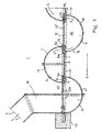
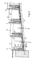
- FIG. 1 and 2 show a first embodiment of the Fish pass system (1), which consists of pools (4) with a Semicircular area as the base area (4G).
- the pipe section (41) forming the first pool wall (11) has one Center angle (4ZW) of 180 ° and the second pool wall (12)
- the connecting piece (42T) is a plate (42), the Length less than the diameter (d1) of the semicircle or Beckens (4) is.
- the plate is used to form a basin (4) (42) arranged on the diameter of the semicircle line, i.e. in the opening between the edges (13) of the first pool wall (12).
- the remaining distance to the neighboring inner wall of the pool forms the inflow and an outflow slot (5Z, 5A).
- the center points of the semicircle diameter (d1) lie on an imaginary one, oriented in the direction of the slope (G) Straight lines (G1), whereas the center points (MP) of the semi-cylindrical basin (4) on a zigzag extending line (V) are arranged so that all Flow slots (5) are perpendicular to the slope (G) and a tangential in the area of the flow slots (5) inlet and outlet flow (S) running along the inner wall of the pool formed.
- the fish ladder system (1) consists of two individual parts (1E) with alternately arranged half-pipe pieces (41) and plates (42 *).
- For a final assembly of the Fish ladder system (1) are the pre-assembled in operation Individual parts (1E) transported to the construction site. Alternatively, you can the individual parts (1E) are also assembled on site in the dry become. Then the base plates (28P) are glued in and the Prefabricated pool system is on a hot-dip galvanized Steel ladder scaffold fixed, then with concrete foundations (43) is anchored in the bank area.
- This first embodiment will have a lower one Connection trench (35) and via an upper connection trench (32) (not shown) to the river (31F) connected.
- the connecting trenches (32, 35) are on the top open channels with a rectangular cross-section Fiber cement, the top and bottom, respectively semi-cylindrical basin (4) with the flowing water (31F) connect.
- a multi-part construction allows an optimal, flexible connection to the river (31F); so can in principle also angled fish lifts (1) be constructed.
- Fig. 2 is a flow slot (5) with the height itself changing cross-section shown.
- Cross-sectional narrowing becomes the amount of water required for one safe operation of the system (1) and a Fine adjustment of the water level can be made.
- to Cross-sectional changes are bilateral over the Flow slot (5) limiting deflection means (6) two each Shorter semi-cylindrical tubes (61, 62) with a longitudinal one Opening pushed as sliding block (61, 62).
- This Oversleeves (61, 62) have one compared to one Outside diameter of the pipe immediately below (60, 61), slightly larger inner diameter - Fig. 9 -.
- the flow slot (5) is preferably narrowed at the bottom.
- Preferred gradations of the flow slot widths are 4.5 cm, 6.0 cm and 8.5 cm, with a water volume of 60 l / sec. or 8.0 cm, 10.5 cm and 13.0 cm with a water volume of 600 l / sec.
- edges (13) of the basin (4) are of sliding blocks (60, 61, 62) with decreasing length and increasing diameter jacketed.
- sliding blocks 60, 61, 62
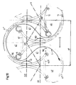
- the second embodiment is a Fish lift system (1) shown.
- the basins (4) exist from two different sized pieces of pipe (41 *, 42) as one first and second pool wall (11, 12), which form the Circle segment as a base (4G) opposite to each other are arranged.
- the first pool wall (11) has one Center angle of 300 ° and the second pool wall (12) has one Center angle of 50 °.
- the second pool wall (12) is approximate arranged on the tendon of the first pool wall (11).
- the system shown (1) consists of eleven stages, the first pool walls (11) with their openings (4 ⁇ ) alternately aligned to the center line (M) of the fish pass (1) are.
- the center points (MP) of the pelvis (4a, 4c; 4b, 4d) with same orientation lie on two parallel, imaginary, in Direction of the slope (G) of the straight line (G1, G2).
- the Centers (MP) of the pools (4a, 4b, 4c, 4d)) are on an imaginary, zigzag running connecting line (V), the between the The resulting angle is always the same size.
- the Flow slots (5) are congruent with the Connection line approximately in the middle of one leg.
- the pools (4) each form a step, since they are within a pool (4) the pelvic floor (28) not with the same slope (G) runs, but in the inlet area (4EB) of the slope (G) is inclined and in the outlet area (4AB) by a counter berm (8) rises horizontally or slightly against the slope (G) - Fig. 4 -.
- the slope of the counter berm (8) approximately the same value as the slope (G).
- the successive pools (4a, 4b, 4c, 4d) represent one Kind, with a spiral staircase running along an inclined plane each walking line broken by more than 180 ° (flow thread) represents, with outlet (water inlet ((2) and entry (Water drain) (3) on the same side of the carpet, namely on the on the water side of the stairs.
- the basins (4) have an overflow channel (22) Fiber cement, including the second pool wall (12) and the immediately following first pool wall (11) of the next Basin (4) each on the upper edge (16) of a common one Corner (17) have a semicircular cutout (18).
- the apex of the cutout (18) is approximately 15 cm from the top of the pool (16).
- the center of the Cutouts lie in an axis (21), so that in the Cutouts (18) a half-shell embedded in melt mortar (22) can be inserted.
- This overflow channel (22) is at Flood level floods and serves in particular the Large salmonids, such as salmon and sea trout, as Uphill.
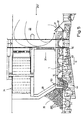
- Fig. 4 shows that mounted on a reinforced concrete slab (54) Fish lift system (1).
- To manufacture is in the bank area a cleanliness layer (56) in the vicinity of the transverse lining subtracted from the local gradient (G).
- Basin (4) with galvanized angles on the concrete slab (54) secured. Internal seams between the pelvic floor (28) and pool walls (4) with a Thiocolfuge or screed sealed.
- the pools (4) are on the outside for stabilization supported with an inclined cement foot (55) made of special cement, which also acts as a seal.
- the fish ladder system (1) After assembly, the fish ladder system (1), as Fig. 3rd shows, secured by palisades or concrete walls Connection trenches (32, 35) to the upper storage area (33) and to lower discharge area (36) into the flowing water (31F) integrated.
- 5 to 7 is the inclusion of a Fish pass system (1) into a river (31) with a Transverse installation (34) is shown schematically.
- FIGS. 5 is a fish ladder system (1) according to FIGS. 1 and 2 parallel to a weir (34) in its bank area (44) integrated, in the water drain (3) are for reinforcement Lure flow (S) additional sediments (29) set.
- the trickle water (31) flowing over a weir (34) is by means of a guide and deflection element (39) in the form of a channel caught and through a connected drain pipe (53) in the bottom basin (4) of the system (1) so that the attraction flow at the outlet (3) is increased.
- the flap (37) is preferred articulated in such a way that the dynamic pressure on the inflow flap (37), which flows through the flow over the transverse structure (34) Flow is caused, the flap (37) closes tightly.
- a slide can be provided.
- Fig. 6 shows one installed in the flowing water (31F) Schottenwehr (34) with a fish pass (1) as a bypass 3 and 4, wherein the lower connection trench (35) to increase the attraction flow at an acute angle to the lower reaches (36) is arranged.
- the water drain (3) opens with about 30 ° to the assigned bank in the lower reaches (36).
- the upper and lower connecting trench (32, 35) to the upper one Storage area (33) or to the lower discharge area (36) of the Running water (31F) is secured by palisades.
- Coming soon in the upper connecting trench (32) are palisade bulkheads Formation of a funnel tapering in the direction of flow set, and it's a 30 cm below the Threshold lying on the water surface is around the To hold attachments and to enter flotsam into the To prevent plant (1).
- the trickle water (32) flowing out over the bulkhead weir (34) is arranged at the base of the weir support surface Guide and deflection element (39) in the form of a screed Larch wood, with a cross section of 6 x 12 cm, for connection trench (35) on the underside.
- Fig. 7 is an analogous arrangement of the fish pass (1) shown in FIG. 6, with a coating weir (34) River (31F) is dammed up and the lower connection ditch (35) is not arranged at an acute angle.
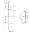
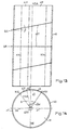
- a tube (45) is cut across the tube axis (45A) cuts in the same large pieces of pipe with a Cut length of at least 70 cm, the cuts alternating perpendicular to the pipe axis (45A) Cross sections (QS) and under one through a slope (G) in the Fish ladder system (1) predetermined cutting angle ( ⁇ ) for Pipe axis (45A) are cross sections (QS).
- the Cutting angle is between 10 to 40 °, preferably 15 ° up to 20 ° for in flowing waters (31F) and from 20 ° to 30 ° for in Dams (31T) integrated fish lifts (1).
- the tube (45) has a diameter (d1) of 0.8 to 5 m, preferably 1 to 3 m. It will preferably be commercially available Prefabricated pipes (45) made of fiber cement, glass fiber cement or the like. As Starting material used.
- the cut out is cut out by further coaxial cuts Sector piece (42) separated into at least two sections (42T), connecting pieces (42) forming around second pool walls (12) produce. These connectors (42) are used to close the Intermediate space between adjacent edges (13a, 13b) arranged basin (4a, 4c, 4b, 4d) with the same orientation used.
Landscapes
- Engineering & Computer Science (AREA)
- General Engineering & Computer Science (AREA)
- Life Sciences & Earth Sciences (AREA)
- Marine Sciences & Fisheries (AREA)
- Mechanical Engineering (AREA)
- Civil Engineering (AREA)
- Structural Engineering (AREA)
- Farming Of Fish And Shellfish (AREA)
- Revetment (AREA)
- Ladders (AREA)
- Artificial Fish Reefs (AREA)
Claims (33)
- Echelle à poissons pour surmonter une hauteur de retenue, avec un afflux d'eau en amont (2) et un écoulement d'eau en aval (3) et avec, entre ceux-ci, des bassins (4) disposés les uns à la suite des autres, essentiellement dans le sens de la pente (G), lesquels bassins (4) présentent chacun une fente d'amenée (5Z) et une fente d'écoulement (5A) en tant que fentes de circulation verticales (5) et des moyens de déviation (6) pour former un parcours décrivant des méandres,
caractérisée en ce que
les bassins (4) possèdent chacun une paroi intérieure partiellement cylindrique (40) et lesdits bassins (4a, 4b, 4c), disposés les uns à la suite des autres, sont orientés les uns vers les autres et décalés latéralement par rapport les uns aux autres de sorte que les fentes de passage (5) se trouvent orientées transversalement par rapport au sens de chute (G) et que lesdites fentes de passage (5) sont limitées chacune, des deux côtés, sur toute la hauteur du bassin, par un premier tube vertical, partiellement cylindrique (60), en tant que premier moyen de déviation (6), dont le rayon est considérablement plus petit que le rayon des parois intérieures (40) du bassin. - Echelle à poissons selon la revendication 1,
caractérisée en ce que,
sur le premier tube partiellement cylindrique (60), au moins un deuxième tube partiellement cylindrique, vertical, plus court (61, 62) est fixé, lequel présente un diamètre intérieur un peu plus grand que le diamètre extérieur du tube (60, 61) situé directement sous lui, ce dont résulte une modification de la coupe transversale sur la hauteur de la fente de circulation (5). - Echelle à poissons selon la revendication 1 ou 2,
caractérisée en ce que
la largeur de la fente de circulation (5) est d'au moins 30 mm, préférentiellement d'au moins 45 mm. - Echelle à poissons selon l'une ou plusieurs des revendications 1 à 3,
caractérisée en ce que
les bassins (4) présentent une surface de base (4G) égale. - Echelle à poissons selon l'une ou plusieurs des revendications 1 à 4,
caractérisée en ce que
des bassins (4, 4a, 4b, 4c), disposés successivement, présentent, par rapport les uns aux autres, une différence de hauteur (hauteur de chute) de 10 à 25 cm, préférentiellement de 15 cm. - Echelle à poissons selon l'une ou plusieurs des revendications 1 à 5,
caractérisée en ce que
la plus courte des génératrices situées dans le plan de symétrie (SE) d'un bassin (4) couvre au moins 70 cm. - Echelle à poissons selon l'une ou plusieurs des revendications 1 à 6,
caractérisée en ce que
les parois (40) d'un bassin individuel (4) sont formées par une pièce tubulaire partiellement cylindrique (41, 41*), en tant que première paroi de bassin (11), et par un élément (42, 42*), située à l'opposé, en tant que deuxième paroi de bassin (12), et que l'élément (42), en tant que pièce de jonction, réunit des bords voisins (13a, 13b) des pièces tubulaires de bassins opposés (4a, 4c), disposées directement au-dessus ou au-dessous, et que ces bords (13a, 13b) sont gainés par le premier moyen de déviation (6). - Echelle à poissons selon l'une ou plusieurs des revendications 1 à 7,
caractérisée en ce que
la pièce tubulaire (41, 41*) présente, en tant qu'arc de cercle, un angle en centre (4ZW) supérieur à 180°, préférentiellement de 300°, et que, pour former un bassin individuel (4), l'élément (42, 42*) est disposé sur une corde formant l'arc de cercle, de sorte que la superficie du segment de cercle, qui forme une surface de base (4G) du bassin (4), soit plus grande qu'une surface de demi-cercle. - Echelle à poissons selon la revendication 8,
caractérisée en ce que
les bassins (4), pour la formation d'un gradin dans leurs zone d'écoulement (4AB), présentent une contre-berme (8) avec un fond de bassin (28) horizontal ou légèrement ascendant à l'opposé de la pente (G). - Echelle à poissons selon la revendication 8 ou 9,
caractérisée en ce que
l'élément (42, 42*) et la pièce tubulaire (41*) y faisant directement suite présentent chacun, sur le bord supérieur (16) d'un angle commun, une découpe en demi-cercle (18), les points centraux des surfaces semi-circulaires étant situés sur un axe (A), et qu'une semi-coque (22) est insérée dans lesdites découpes (18) en tant que canal de trop-plein (22). - Echelle à poissons selon la revendication 7,
caractérisée en ce que
la pièce tubulaire (41*) présente un angle en centre (4ZW) supérieur à 180°, préférentiellement de 340°, et l'élément (42, 42*) est disposé à l'intérieur de la pièce tubulaire (41*) de sorte à former, à l'intérieur du bassin (4), des bassins partiels (4T) présentant une coupe transversale elliptique et une surface presque égale, et, entre les moyens de déviation (6) et les parois intérieures opposées (11, 12) de bassin, des étranglements (5E) en tant que fentes de circulation (5). - Echelle à poissons selon la revendication 11,
caractérisée en ce que,
en aval des étranglements (5E), une pièce tubulaire partiellement cylindrique (13) est fixée, en tant que deuxième moyen de déviation (62). - Echelle à poissons selon la revendication 7,
caractérisée en ce que
la pièce tubulaire (41) a un angle en centre (4ZW) de 180° et la pièce tubulaire (42, 42*) est disposée sur le diamètre du demi-cercle. - Echelle à poissons selon l'une ou plusieurs des revendications 1 à 13,
caractérisée en ce que
les points centraux des bassins (4a, 4b ; 4c, 4d) orientés dans le même sens forment respectivement une droite imaginaire (G1, G2) s'étendant dans le sens de la pente. - Echelle à poissons selon la revendication 14,
caractérisée en ce que
les points centraux sont distancés régulièrement les uns des autres. - Echelle à poissons selon l'une ou plusieurs des revendications 7 à 15,
caractérisée en ce que
la deuxième paroi de bassin (12) est un secteur tubulaire (42) qui présente une longueur d'arc relativement plus courte que la longueur d'arc de la première paroi de bassin (11) et s'étend, incurvée inversement, vers la paroi intérieure opposée (40) pour former un bassin individuel (4). - Echelle à poissons selon l'une ou plusieurs des revendications 7 à 15,
caractérisée en ce que
la deuxième paroi de bassin (12) est une plaque (42*) qui présente une longueur inférieure au diamètre (d1) du bassin (4). - Echelle à poissons selon l'une ou plusieurs des revendications 1 à 17,
caractérisée en ce que
les bassins (4) présentent des fonds de bassin (28) de structure rugueuse pour la formation d'un système lacunaire (30), ce en vue de quoi des sédiments (29S) d'une grosseur allant de celle d'un poing à celle d'une tête d'enfant et / ou une natte amorphe, à grosses mailles (29M), avec des cavités reliées entre elles, sont fixés au fond du bassin (4). - Echelle à poissons selon l'une ou plusieurs des revendications 1 à 18,
caractérisée en ce que
celle-ci est une unité (1) formant un bypass autour d'un barrage transversal (34) qui retient l'eau d'un cours d'eau (31F) et est reliée audit cours d'eau (31F) par l'intermédiaires de fossés de jonction (32, 35), sécurisés latéralement, un fossé de jonction supérieur (32) partant de la zone de retenue (33), en amont du barrage transversal (34), et un fossé de jonction inférieur (35) conduisant au courant inférieur (36), en aval dudit barrage (34). - Echelle à poissons selon l'une ou plusieurs des revendications 1 à 18,
caractérisée en ce que
celle-ci est une échelle à poissons (1) composée de plusieurs parties qui forme un bypass pour permettre de surmonter un mur de barrage (34M) d'un barrage-réservoir (31T), dans laquelle, du côté retenue du mur de barrage (34M), un secteur supérieur d'échelle (1O) et, du côté espace libre dudit mur de barrage (34M), un secteur inférieur d'échelle 1U), avec un fossé de jonction (35) à destination du courant inférieur (36) sont déterminés et que les deux secteurs (1O, 1U) sont reliés par un canal de liaison (1V) qui traverse le mur de barrage (34M). - Echelle à poissons selon la revendication 19 ou 20,
caractérisée en ce que
le fossé de jonction (35) conflue avec le courant inférieur (36) en'formant avec la rive associée un angle aigu qui est préférentiellement de 30° environ. - Echelle à poissons selon la revendications 19 ou 20,
caractérisée en ce que,
dans le courant inférieur, transversalement entre les rives latérales (38), un organe de guidage et de déviation est disposé, dont l'extrémité côté échelle à poissons est située dans la zone de l'embouchure du fossé de jonction inférieur (35). - Echelle à poissons selon l'une ou plusieurs des revendications 1 à 22,
caractérisée en ce que
celle-ci est composée d'éléments pré-montés (1E) comprenant des pièces tubulaires (41, 41*) orientées dans le même sens et de pièces de jonction (42, 42*) disposées entre celles-ci, lesquelles pièces de jonction (42, 42*) peuvent être ancrées dans le secteur riverain (44), sur une plaque de sol (28P), à l'aide de fondations individuels (43). - Procédé pour la fabrication d'un bassin pour une échelle à poissons selon l'une ou plusieurs des revendications 1 à 23,
caractérisé en ce que
un tube (45) peut être divisé en plusieurs portions égales (45T) par des coupes transversales (QR), orientées alternativement à angle droit par rapport à l'axe (45A) dudit tube, et des coupes transversales (QS) orientées par rapport à l'axe (45A) dudit tube sous un angle de coupe (W) prédéterminé par une pente (G) de l'échelle à poissons, au moins une paroi de bassin partiellement cylindrique, au moins, étant ensuite réalisée avec lesdites portions de tube (45T), à l'aide de coupes coaxiales (KS), orientées parallèlement à l'axe du tube (45A). - Procédé selon la revendication 24,
caractérisé en ce que
l'angle de coupe α est de 10° à 40°, préférentiellement de 15° à 20° pour les échelles à poissons (1) intégrées dans des eaux courantes (31F) et de 20° à 30° pour celles intégrées dans des barrages-réservoirs. - Procédé selon la revendication 24 ou 25,
caractérisé en ce que
les portions de tube (45T) présentent une longueur d'au moins 70 cm. - Procédé selon l'une ou plusieurs des revendications 24 à 26,
caractérisé en ce que,
dans les différentes portions de tube (45T), pour la réalisation d'une paroi de bassin (40) présentant une ouverture (4Ö), un secteur (42) est découpés à l'aide de coupes coaxiales (KS) disposées monolatéralement par rapport à leur plan de symétrie (SE). - Procédé selon l'une ou plusieurs des revendications 24 à 27,
caractérisé en ce que
le secteur (42) est découpé dans la portion de tube (45T), dans la zone où un plan bissecteur (WE) de l'ouverture (4Ö) est à angle droit par rapport au plan de symétrie (SE). - Procédé selon la revendication 27 ou 28,
caractérisé en ce que
le secteur (42) présente un angle en centre (4ZW) de 10° et 180°, préférentiellement de 20° à 60°. - Procédé selon l'une ou plusieurs des revendications 24 à 26,
caractérisé en ce que
les différentes portions de tube (45T) sont divisées chacune en deux moitiés égales, par des coupes coaxiales (KS1), situées dans leur plan de symétrie (SE), lesquelles moitiés peuvent être intégrées dans l'échelle à poissons, en tant que parois de bassin (40), pour former un bassin semi-cylindrique (41). - Prccédé selon l'une ou plusieurs des revendications 24 à 26,
caractérisé en ce que
le secteur (42) est divisé, par au moins une autre coupe coaxiale (KS2), en au moins deux parties (42T) qui, pour former un bassin (4) entre des bords voisins (13a, 13b) de parois de bassin (4a, 4c) disposées l'une à côté de l'autre, orientées dans le même sens, peuvent être intégrées dans l'échelle à poissons. - Procédé selon l'une ou plusieurs des revendications 24 à 31,
caractérisé en ce que
le tube (45) a un diamètre (dl) de 0,8 à 5 m, préférentiellement de 1 à 3 m. - Procédé selon l'une ou plusieurs des revendications 24 à 32,
caractérisé en ce que
les tubes (45) sont réalisés en fibrociment, en ciment armé de fibres de verre ou en autres matières analogues.
Applications Claiming Priority (3)
| Application Number | Priority Date | Filing Date | Title |
|---|---|---|---|
| DE19622096 | 1996-06-01 | ||
| DE19622096A DE19622096C2 (de) | 1996-06-01 | 1996-06-01 | Fischaufstiegsanlage und deren Herstellungsverfahren |
| PCT/EP1997/002850 WO1997046761A1 (fr) | 1996-06-01 | 1997-06-02 | Echelle a poissons |
Publications (2)
| Publication Number | Publication Date |
|---|---|
| EP0901540A1 EP0901540A1 (fr) | 1999-03-17 |
| EP0901540B1 true EP0901540B1 (fr) | 2003-09-24 |
Family
ID=7795920
Family Applications (1)
| Application Number | Title | Priority Date | Filing Date |
|---|---|---|---|
| EP97927100A Expired - Lifetime EP0901540B1 (fr) | 1996-06-01 | 1997-06-02 | Echelle a poissons |
Country Status (7)
| Country | Link |
|---|---|
| US (1) | US6155746A (fr) |
| EP (1) | EP0901540B1 (fr) |
| AT (1) | ATE250695T1 (fr) |
| AU (1) | AU3171097A (fr) |
| CA (1) | CA2256402A1 (fr) |
| DE (2) | DE19622096C2 (fr) |
| WO (1) | WO1997046761A1 (fr) |
Families Citing this family (21)
| Publication number | Priority date | Publication date | Assignee | Title |
|---|---|---|---|---|
| FI103356B (fi) * | 1997-06-17 | 1999-06-15 | Pohjamo Timo | Kalatiejärjestelmä |
| US6394699B1 (en) * | 1999-07-28 | 2002-05-28 | Norman R. Neufeld | Apparatus for reduced flow fish passage |
| DE10006173C2 (de) * | 2000-02-11 | 2002-06-13 | Beate Adam | Transportvorrichtung für flußabwärts wandernde Fische |
| US6793440B2 (en) | 2002-01-15 | 2004-09-21 | The United States Of America As Represented By The Secretary Of The Army | Natural cue surface bypass collector |
| US6715959B2 (en) * | 2002-07-24 | 2004-04-06 | Bga Limited Partnership | Fish ladder for passing dams |
| US6726404B2 (en) | 2002-08-20 | 2004-04-27 | The United States Of America As Represented By The Secretary Of The Army | Device and method for simulating natural cues so that waterborne fauna avoid contacting manmade barriers |
| DE10331596B4 (de) | 2003-07-11 | 2005-10-27 | Hans Wilhelm Peters | Fischpass |
| RU2269620C1 (ru) * | 2004-07-28 | 2006-02-10 | Федеральное государственное образовательное учреждение высшего профессионального образования "Новочеркасская государственная мелиоративная академия" ФГОУ ВПО (НГМА) | Рыбоходно-нерестовый канал |
| RU2310714C2 (ru) * | 2006-01-10 | 2007-11-20 | Федеральное государственное образовательное учреждение высшего профессионального образования "Новочеркасская государственная мелиоративная академия" ФГОУ ВПО (НГМА) | Рыбоход |
| NL1032819C2 (nl) * | 2006-11-06 | 2008-05-08 | Witteveen En Bos Raadgevende I | Visgeleidingssysteem. |
| US20160017558A1 (en) | 2010-04-23 | 2016-01-21 | French Development Enterprises, LLC | Aquatic Animal Passage With Counter |
| US10760233B2 (en) | 2010-04-23 | 2020-09-01 | French Development Enterprises, LLC | Precast dam structure with flowpath |
| DE202012104612U1 (de) | 2012-11-27 | 2012-12-03 | Rehart Gmbh | Wasserkraftanlage |
| CN108118667B (zh) * | 2018-01-08 | 2023-05-02 | 三峡大学 | 一种仿自然式斜坡鱼道及进鱼方法 |
| US12180665B2 (en) | 2019-02-14 | 2024-12-31 | W.L. French Hydropower Holdings Llc | Modular precast pumped storage hydro system for power generation |
| CN109868788B (zh) * | 2019-03-12 | 2024-01-23 | 中国电建集团中南勘测设计研究院有限公司 | 一种浮体装置 |
| CA3175095A1 (fr) | 2020-03-12 | 2021-09-16 | Henry K. Obermeyer | Systeme de passage de poissons pour barrages a haute et moyenne hauteur |
| CN111535257A (zh) * | 2020-06-01 | 2020-08-14 | 上海勘测设计研究院有限公司 | 堰坝组合结构 |
| CN112987833B (zh) * | 2021-05-13 | 2021-07-30 | 武汉中科瑞华生态科技股份有限公司 | 光源控制方法、装置及设备 |
| US12612889B2 (en) | 2024-02-09 | 2026-04-28 | W.L. French Hydropower Holdings Llc | Modular hydropower systems and methods with pumped storage |
| US12612751B2 (en) | 2024-02-09 | 2026-04-28 | W.L. French Hydropower Holdings Llc | Modular precast hydro dam with powerhouse |
Family Cites Families (6)
| Publication number | Priority date | Publication date | Assignee | Title |
|---|---|---|---|---|
| US132349A (en) * | 1872-10-22 | Improvement in fish-ways | ||
| US437202A (en) * | 1890-09-30 | Robert hockin | ||
| US1621170A (en) * | 1925-07-17 | 1927-03-15 | Landau William Charles | Fishway |
| US1730005A (en) * | 1926-07-16 | 1929-10-01 | Ellsworth T Grether | Hydrostep for fish streams |
| US1680722A (en) * | 1926-11-23 | 1928-08-14 | Arthur A Bennett | Fish elevator |
| GB1451944A (en) * | 1973-10-06 | 1976-10-06 | Aeroceanics Fishways Corp | Fishway |
-
1996
- 1996-06-01 DE DE19622096A patent/DE19622096C2/de not_active Expired - Fee Related
-
1997
- 1997-06-02 CA CA002256402A patent/CA2256402A1/fr not_active Abandoned
- 1997-06-02 EP EP97927100A patent/EP0901540B1/fr not_active Expired - Lifetime
- 1997-06-02 AU AU31710/97A patent/AU3171097A/en not_active Abandoned
- 1997-06-02 AT AT97927100T patent/ATE250695T1/de not_active IP Right Cessation
- 1997-06-02 US US09/194,699 patent/US6155746A/en not_active Expired - Fee Related
- 1997-06-02 WO PCT/EP1997/002850 patent/WO1997046761A1/fr not_active Ceased
- 1997-06-02 DE DE59710786T patent/DE59710786D1/de not_active Expired - Fee Related
Also Published As
| Publication number | Publication date |
|---|---|
| AU3171097A (en) | 1998-01-05 |
| WO1997046761A1 (fr) | 1997-12-11 |
| EP0901540A1 (fr) | 1999-03-17 |
| ATE250695T1 (de) | 2003-10-15 |
| DE19622096A1 (de) | 1997-12-04 |
| US6155746A (en) | 2000-12-05 |
| DE19622096C2 (de) | 1998-08-27 |
| DE59710786D1 (de) | 2003-10-30 |
| CA2256402A1 (fr) | 1997-12-11 |
Similar Documents
| Publication | Publication Date | Title |
|---|---|---|
| DE19622096C2 (de) | Fischaufstiegsanlage und deren Herstellungsverfahren | |
| EP2098640A2 (fr) | Dispositif de descente d'anguilles sur des bâtiments maritimes | |
| EP3149247B1 (fr) | Passe à poissons | |
| DE10331596B4 (de) | Fischpass | |
| DE10006173C2 (de) | Transportvorrichtung für flußabwärts wandernde Fische | |
| EP0116153A1 (fr) | Dispositif de protection pour réduire la vitesse du vent | |
| DE102010037926A1 (de) | Wasserkraftanlage | |
| DE202005019792U1 (de) | Mäandrierender Fischpass | |
| EP2157243B1 (fr) | Installation de déplacement d'organismes | |
| DE102009044069B4 (de) | Fischaufstiegsanlage zur Überwindung eines Wanderhindernisses in einem Fließgewässer | |
| AT9955U1 (de) | Anordnung an fliessenden gewässern | |
| AT520908B1 (de) | Vorrichtung zur Wanderung von Wassertieren an Barrieren in Gewässern | |
| DE102016111780A1 (de) | Floßartige Vorrichtung | |
| EP2441890A1 (fr) | Passage à poissons à méandre pour bateau | |
| DE202007013837U1 (de) | Fischaufstiegshilfe | |
| CH714146A2 (de) | Wasserführungseinheit für eine Fischaufstiegsanlage und Fischaufstiegsanlage mit einer Mehrzahl von miteinander verbundenden Wasserführungseinheiten. | |
| EP3361005A1 (fr) | Aménagement de cours d'eau | |
| EP4339375B1 (fr) | Dispositif pour la migration d'animaux aquatiques | |
| EP3173530A1 (fr) | Dispositif de migration d'animaux aquatiques vers des barrières dans des eaux | |
| DE19533176C2 (de) | Kaskadenelement zum Abtreppen eines Wasserlaufgefälles | |
| EP0174968A1 (fr) | Installation pour le traitement des eaux usees des routes. | |
| DE102022002208A1 (de) | Fischabstieg | |
| DE3932864A1 (de) | Entwaesserungsrinne fuer die oberflaechenentwaesserung | |
| DE3935686A1 (de) | Balkenelement, insbesondere aus beton | |
| WO2012025466A1 (fr) | Caniveau pour évacuer l'eau de surface |
Legal Events
| Date | Code | Title | Description |
|---|---|---|---|
| PUAI | Public reference made under article 153(3) epc to a published international application that has entered the european phase |
Free format text: ORIGINAL CODE: 0009012 |
|
| 17P | Request for examination filed |
Effective date: 19981119 |
|
| AK | Designated contracting states |
Kind code of ref document: A1 Designated state(s): AT BE CH DE DK FR GB IE IT LI NL SE |
|
| 17Q | First examination report despatched |
Effective date: 20020709 |
|
| GRAH | Despatch of communication of intention to grant a patent |
Free format text: ORIGINAL CODE: EPIDOS IGRA |
|
| GRAS | Grant fee paid |
Free format text: ORIGINAL CODE: EPIDOSNIGR3 |
|
| GRAA | (expected) grant |
Free format text: ORIGINAL CODE: 0009210 |
|
| AK | Designated contracting states |
Kind code of ref document: B1 Designated state(s): AT BE CH DE DK FR GB IE IT LI NL SE |
|
| PG25 | Lapsed in a contracting state [announced via postgrant information from national office to epo] |
Ref country code: NL Free format text: LAPSE BECAUSE OF FAILURE TO SUBMIT A TRANSLATION OF THE DESCRIPTION OR TO PAY THE FEE WITHIN THE PRESCRIBED TIME-LIMIT Effective date: 20030924 Ref country code: IT Free format text: LAPSE BECAUSE OF FAILURE TO SUBMIT A TRANSLATION OF THE DESCRIPTION OR TO PAY THE FEE WITHIN THE PRESCRIBED TIME-LIMIT;WARNING: LAPSES OF ITALIAN PATENTS WITH EFFECTIVE DATE BEFORE 2007 MAY HAVE OCCURRED AT ANY TIME BEFORE 2007. THE CORRECT EFFECTIVE DATE MAY BE DIFFERENT FROM THE ONE RECORDED. Effective date: 20030924 Ref country code: IE Free format text: LAPSE BECAUSE OF FAILURE TO SUBMIT A TRANSLATION OF THE DESCRIPTION OR TO PAY THE FEE WITHIN THE PRESCRIBED TIME-LIMIT Effective date: 20030924 Ref country code: GB Free format text: LAPSE BECAUSE OF FAILURE TO SUBMIT A TRANSLATION OF THE DESCRIPTION OR TO PAY THE FEE WITHIN THE PRESCRIBED TIME-LIMIT Effective date: 20030924 Ref country code: FR Free format text: LAPSE BECAUSE OF FAILURE TO SUBMIT A TRANSLATION OF THE DESCRIPTION OR TO PAY THE FEE WITHIN THE PRESCRIBED TIME-LIMIT Effective date: 20030924 |
|
| REG | Reference to a national code |
Ref country code: GB Ref legal event code: FG4D Free format text: NOT ENGLISH |
|
| REG | Reference to a national code |
Ref country code: CH Ref legal event code: EP |
|
| REG | Reference to a national code |
Ref country code: IE Ref legal event code: FG4D Free format text: GERMAN |
|
| REF | Corresponds to: |
Ref document number: 59710786 Country of ref document: DE Date of ref document: 20031030 Kind code of ref document: P |
|
| PG25 | Lapsed in a contracting state [announced via postgrant information from national office to epo] |
Ref country code: SE Free format text: LAPSE BECAUSE OF FAILURE TO SUBMIT A TRANSLATION OF THE DESCRIPTION OR TO PAY THE FEE WITHIN THE PRESCRIBED TIME-LIMIT Effective date: 20031224 Ref country code: DK Free format text: LAPSE BECAUSE OF FAILURE TO SUBMIT A TRANSLATION OF THE DESCRIPTION OR TO PAY THE FEE WITHIN THE PRESCRIBED TIME-LIMIT Effective date: 20031224 |
|
| NLV1 | Nl: lapsed or annulled due to failure to fulfill the requirements of art. 29p and 29m of the patents act | ||
| GBV | Gb: ep patent (uk) treated as always having been void in accordance with gb section 77(7)/1977 [no translation filed] |
Effective date: 20030924 |
|
| REG | Reference to a national code |
Ref country code: IE Ref legal event code: FD4D |
|
| PG25 | Lapsed in a contracting state [announced via postgrant information from national office to epo] |
Ref country code: AT Free format text: LAPSE BECAUSE OF NON-PAYMENT OF DUE FEES Effective date: 20040602 |
|
| PG25 | Lapsed in a contracting state [announced via postgrant information from national office to epo] |
Ref country code: BE Free format text: LAPSE BECAUSE OF NON-PAYMENT OF DUE FEES Effective date: 20040630 |
|
| PLBE | No opposition filed within time limit |
Free format text: ORIGINAL CODE: 0009261 |
|
| STAA | Information on the status of an ep patent application or granted ep patent |
Free format text: STATUS: NO OPPOSITION FILED WITHIN TIME LIMIT |
|
| 26N | No opposition filed |
Effective date: 20040625 |
|
| EN | Fr: translation not filed | ||
| BERE | Be: lapsed |
Owner name: *PETERS HANS WILHELM Effective date: 20040630 |
|
| PG25 | Lapsed in a contracting state [announced via postgrant information from national office to epo] |
Ref country code: DE Free format text: LAPSE BECAUSE OF NON-PAYMENT OF DUE FEES Effective date: 20050101 |
|
| REG | Reference to a national code |
Ref country code: CH Ref legal event code: PL |
|
| REG | Reference to a national code |
Ref country code: CH Ref legal event code: AEN Free format text: DAS PATENT IST AUFGRUND DES WEITERBEHANDLUNGSANTRAGS VOM 11.02.2004 REAKTIVIERT WORDEN. |
|
| PGFP | Annual fee paid to national office [announced via postgrant information from national office to epo] |
Ref country code: CH Payment date: 20140522 Year of fee payment: 18 |
|
| REG | Reference to a national code |
Ref country code: CH Ref legal event code: PL |
|
| PG25 | Lapsed in a contracting state [announced via postgrant information from national office to epo] |
Ref country code: CH Free format text: LAPSE BECAUSE OF NON-PAYMENT OF DUE FEES Effective date: 20150630 Ref country code: LI Free format text: LAPSE BECAUSE OF NON-PAYMENT OF DUE FEES Effective date: 20150630 |