EP3149247B1 - Passe à poissons - Google Patents
Passe à poissons Download PDFInfo
- Publication number
- EP3149247B1 EP3149247B1 EP15711038.8A EP15711038A EP3149247B1 EP 3149247 B1 EP3149247 B1 EP 3149247B1 EP 15711038 A EP15711038 A EP 15711038A EP 3149247 B1 EP3149247 B1 EP 3149247B1
- Authority
- EP
- European Patent Office
- Prior art keywords
- water
- receiving space
- flow
- individual
- water receiving
- Prior art date
- Legal status (The legal status is an assumption and is not a legal conclusion. Google has not performed a legal analysis and makes no representation as to the accuracy of the status listed.)
- Active
Links
Images






Classifications
-
- E—FIXED CONSTRUCTIONS
- E02—HYDRAULIC ENGINEERING; FOUNDATIONS; SOIL SHIFTING
- E02B—HYDRAULIC ENGINEERING
- E02B8/00—Details of barrages or weirs ; Energy dissipating devices carried by lock or dry-dock gates
- E02B8/08—Fish passes or other means providing for migration of fish; Passages for rafts or boats
- E02B8/085—Devices allowing fish migration, e.g. fish traps
-
- Y—GENERAL TAGGING OF NEW TECHNOLOGICAL DEVELOPMENTS; GENERAL TAGGING OF CROSS-SECTIONAL TECHNOLOGIES SPANNING OVER SEVERAL SECTIONS OF THE IPC; TECHNICAL SUBJECTS COVERED BY FORMER USPC CROSS-REFERENCE ART COLLECTIONS [XRACs] AND DIGESTS
- Y02—TECHNOLOGIES OR APPLICATIONS FOR MITIGATION OR ADAPTATION AGAINST CLIMATE CHANGE
- Y02A—TECHNOLOGIES FOR ADAPTATION TO CLIMATE CHANGE
- Y02A40/00—Adaptation technologies in agriculture, forestry, livestock or agroalimentary production
- Y02A40/60—Ecological corridors or buffer zones
Definitions
- the invention is in the field of water body and relates to a single basin for a fish ladder for fish to overcome an obstacle between a top water inlet and a bottom water drain and a fish ladder.
- the fish ladder includes a plurality of interconnected, a flow path forming single basins each having a, a water receiving space forming outer wall assembly and a transfer slot opening for the flow of water between adjacent single basins.
- Such fish passages are also referred to as fish pass, fishway, fish migration aid or colloquially as fish ladder.
- a fish ladder is a hydraulic device on rivers to fish, z. As in the context of fish migration, and possibly also other aquatic organisms to give the opportunity to overcome obstacles such as weirs, power plant stages, stages in general, waterfalls or generally a gradient.
- the obstacles can be artificial or natural.
- the publication DE 20 2005 010 752 U1 describes a fish ladder, which is composed of individual troughs. The arrangement of the troughs takes place one above the other about a central axis.
- the fish ladder is made of factory-made, equal parts.
- the publication EP 2 157 243 A2 discloses a fish migration aid comprising at least two slot passes along a first length and at least one pelvis, the pelvis being formed between each two of the at least two slot passes.
- Each slot passage forms at least one slot included in the fish migration aid for the flow of water in a slot flow direction.
- the publication AT 9 955 U1 discloses an arrangement designed as a fish migration aid on flowing waters, which comprises flow-calmed spaces into which mounting bodies contribute to calm the flow.
- the fish ladder should be quick and easy to assemble.
- the fish ladder should also be quickly and easily and reusable degradable and convertible.
- a further object of the present invention is to provide with the fish ladder optimal ascent conditions for the fish. This should be achieved, inter alia, by optimal flow conditions.
- the fish ladder should also create optimal descent conditions for the fish.
- the amount of hot water for the operation of the fish ladder should be kept as low as possible, since this water is otherwise lacking in power plants to produce electrical energy.
- the fish ladder should also be suitable for the ascent and descent of macrozoobenthos.
- Macrozoobenthos is a collective term for animal organisms that live on the water bottom and are particularly recognizable by the eye. Such animal organisms may be snails, small crabs, bivalves, worms or insect larvae.
- the invention is characterized in that the individual basins each contain an inner wall arrangement, which subdivide the receiving space of the individual basins in each of a first and second water receiving space, wherein the water receiving chambers via a flow passage opening for the flow of water from the first water receiving space into the second water receiving space interconnected are.
- the flow slot opening may be formed entirely through the inner wall assembly or through the inner and outer wall assemblies.
- the outer wall arrangement of the single basin further forms, upstream in particular, an inlet opening to the first water receiving space.
- the opening cross section of the inlet opening is in particular equal to or greater than the opening cross section of the transfer slot opening.
- the opening cross section of the inlet opening is in particular equal to or greater than the opening cross section of the flow-through slot opening.
- the single basin with the first and second water receiving space is designed so that the water flows through the inlet opening into the first water receiving space, then through the flow slot opening into the second water receiving space and from there via the transfer slot opening again from the single basin out.
- the water flows out through the transfer slot opening out of a first single basin arranged upstream and via the inlet opening into a second single basin following immediately downstream.
- the single basins can also be called single vessels.
- the individual pools each contain in particular a floor.
- the bottom of the individual vessels is aligned in the fish ladder, ie in operating position, in particular horizontally.
- the bottom of the single basin can be permeable. This can be the case, in particular, for single basins of the fish ladder, which lie directly against the ground or the river bottom. This applies in particular to the downstream, lowest single basin whose transfer slot opening opens into the mouth area in the underwater.
- the soil is so permeable to the ground or to the water body, so that organisms from the subsoil or the water body through the permeable Soil into the single basin, in particular in the sole in a single basin forming substrate can penetrate and vice versa.
- the permeable bottom can be formed for example by a perforated wall or by wire mesh or a wire mesh.
- the size of the individual pools is dependent on the size of the largest fish to pass the fish ladder. As a rule of thumb, the length of the pool should be at least three times longer than the longest fish.
- the opening slots are particularly vertical or substantially vertically aligned.
- Aligned substantially vertically means an angle of less than 45 ° (degrees), in particular 20 °, relative to a vertical.
- the opening slots (flow opening slots, transfer opening slots), also called slot gates, can have a uniform slot width over their longitudinal extent or vertical extent.
- the slot width can also decrease towards the bottom continuously or stepwise.
- the opening slot may be V-shaped.
- the opening slots are especially open towards the top.
- the opening slots can reach to the bottom of the single tank or to the sole in a single tank.
- the opening slots represent a narrowing of the flow area, which leads to an acceleration of the flow.
- the accelerated flow has, inter alia, the effect of a lock flow or guide flow for the fish.
- the opening slits in the tank repeatedly ensure lock flows along the throughflow.
- the outer wall arrangement comprises outer walls which bound the receiving space of the individual basins to the outside.
- the inner wall assembly includes one or more inner walls within the outer wall assembly.
- the walls of the inner wall assembly may be formed lower than the walls of the outer wall assembly.
- the second water receiving space can in particular be formed by inner walls of the inner wall arrangement and by outer walls of the outer wall arrangement.
- the water receiving chambers are formed by the inner and outer walls in particular as chambers. These are especially designed to be open at the top. So that the fish in the fish pass are protected against predators, such as herons, the water reservoirs or the individual basins can have a complete or partial cover towards the top.
- the cover may be detachably mounted.
- the transfer slot opening is in particular a discharge opening for the outflow of water from the second water receiving space of the first single basin into the first water receiving space of the adjacent second single basin.
- the transfer slot opening is therefore arranged in the individual basins in particular so that the water can flow out of the second water receiving space of an upstream, adjacent single basins via the transfer slot opening into the first water receiving space of a downstream adjoining second single basin.
- the transfer slot opening may be formed by inner walls.
- the transfer slot opening can also be formed by outer walls.
- the transfer slot opening may also be formed by a first wall portion of the inner wall assembly and a second wall portion of the outer wall assembly.
- the transfer slot opening or the second water receiving space is designed so that, when the water flows through the transfer slot opening, a change in the direction of flow, in particular with respect to the direction of flow, is forced through the flow slot opening.
- the water flowing through the transfer slot opening is introduced obliquely to the mean flow direction into the downstream adjacent single basin.
- the water is directed by this change in direction in particular with respect to the flow direction through the flow-through slot opening or with respect to a main flow direction at an angle in the downstream adjacent single basin.
- the inflow direction into the adjoining single basin is therefore not directed directly to the flow-through slot opening in this single basin.
- the inflowing water is rather deflected towards the calming zone described below.
- the single basin with the first and second receiving space and the calming zone, the flow-through slot opening and the transfer slot opening is in particular designed such that the water in the single basin has an omega ( ⁇ ) -shaped flow profile.
- the water is introduced through the transfer slot opening of the upstream single basin obliquely to the calming zone in the first receiving space of the downstream single basin.
- the water flows in a loop-shaped flow to the calming zone and then in a cross flow to the passage slot opening.
- the second water receiving space is configured in particular in such a way that the direction of the water flowing out of the second water receiving space through the transfer slot opening encloses an angle of greater than 0 ° and less than 90 ° with respect to a flow plane formed by the flow cross section of the inlet opening.
- the angle can be more than 20 °.
- the angle can be more than 30 °.
- the angle can be greater than 40 °.
- the angle can be less than 70 °.
- the angle can be less than 60 °.
- the angle can be less than 50 °.
- the angle can be in particular 45 °.
- the second water receiving space forms a water supply channel with an inflow-side first channel section and an outflow-side second channel section.
- the second channel section is inclined relative to the first channel section by an angle of greater than 0 ° and less than 90 °.
- the second channel section forms the transfer slot opening.
- the angle can be more than 20 °.
- the angle can be more than 30 °.
- the angle can be greater than 40 °.
- the angle can be less than 70 °.
- the angle can be less than 60 °.
- the angle can be less than 50 °.
- the angle can be in particular 45 °.
- the flow cross section of the second channel section is in particular smaller than the flow cross section of the first channel section.
- two single basins can be connected to each other via outer walls, wherein the transfer slot opening of the upstream single basin is merged with the inlet opening of the downstream adjoining single basin.
- the transfer slot opening is formed by two wall sections, which are arranged offset to one another.
- the staggered arrangement can, for. B. be realized by two wall sections which extend in two mutually parallel but spaced-apart planes.
- the transfer slot opening can be adjustable in width, so that the flow rate can be controlled.
- the adjustability can be done by a sliding wall section.
- the displaceable wall portion may be guided in a slot guide.
- the flow slot opening can be adjusted in width in the same way, so that the flow rate can be controlled.
- connection areas or connection interfaces can be formed, via which the single basins can be connected to adjacent single basins.
- the single basin contains in particular a connection area for connecting the single basin to an upstream single basin. Further, the single basin contains a further connection area for connecting the single basin to a single basin arranged downstream.
- the connecting regions may in particular comprise connecting surfaces, via which two adjacent single basins are connected to each other in a planar manner.
- the connecting surfaces may be formed as connecting flanges in the outer wall assembly.
- the interface to the downstream single pool may be extended flange-like beyond the floor. This takes into account the fact that the single basin can be arranged downstream stepped downwards.
- the connecting surface to the upstream single basin may be extended flange over the outer walls upwards. This takes into account that the single basin can be arranged upstream stepped stepped upwards.
- the compound can be solvable in particular.
- the connection can be made via connecting means, such as screws or rivets. So the basins can be connected to each other via screw connections.
- the screw connections can penetrate the connection surfaces.
- the outer wall arrangement forms in each case the inlet opening in the connection area facing upstream.
- the inlet opening forms the inlet into the first water receiving space.
- the inlet opening can reach to the bottom of the single basin.
- the outer wall assembly may each form an outlet opening in the downstream connection region.
- the outlet opening forms an outlet from the single basin into the single basin arranged downstream adjacent to the transfer slot opening.
- the outlet opening can reach to the bottom of the single basin.
- the opening cross section of the outlet opening is in particular equal to or greater than the opening cross section of the transfer slot opening.
- the opening cross section of the outlet opening is in particular equal to or greater than the opening cross section of the flow-through slot opening.
- the inlet opening may for example be bounded by connecting surfaces.
- the outlet opening may for example be bounded by connecting surfaces.
- the connecting surfaces can surround the inlet or outlet opening in a U-shape.
- the inlet or outlet opening is open in particular upwards.
- the flow cross section of the outlet opening is in particular congruent to the flow cross section of the inlet opening.
- the single basin is connected in accordance with a particular embodiment via first connecting surfaces with second connecting surfaces of an upstream arranged, in particular identical, single basin. Furthermore, the single basin is connected via second connecting surfaces with first connecting surfaces of a downstream arranged, in particular identical, single basin.
- Inlet and outlet opening in particular have the same opening cross-section.
- Two adjacent individual basins are each arranged in particular stepped or staircase-shaped stepped against each other. This creates a gradient between two single basins. However, it can also be provided single pool, the receiving space serves as a whole as a rest area. These individual basins are opposite the upstream adjacent single pool in particular at the same height, so not staggered, arranged.
- the fish ladder may contain a supporting structure designed as a substructure.
- the individual basins are supported in particular on the support structure and secured thereto.
- the support structure can be supported by support feet on the terrain.
- the support legs can be supported in particular on a foundation on the terrain.
- the support structure may have a staircase shape.
- the single basins are arranged and fixed on the steps.
- the support structure may in particular be a subframe.
- the base can be made of metal, such as steel.
- the individual basins can also be connected to one another to form a self-supporting structure.
- only the first and the last single basins, which form the end of a sequence of interconnected single basins, can be supported on a support.
- the individual basins can in particular be arranged cantilevered over the water.
- the fish ladder contains a lowermost single basin.
- the transfer slot opening of this single basin opens in particular in a mouth region in the underwater.
- the single basin may contain a funnel-shaped narrowing in the flow direction drainage over which the water flows back into the underwater area of the watercourse.
- the funnel-shaped constriction in the direction of flow causes an acceleration of the flow to the confluence in the watercourse.
- the accelerated flow at the confluence serves as a lock flow for the fish, so that the fish find the entrance to the fish ladder better.
- a water pipe can be provided by means of which additional water can be provided for the confluence of the fish ladder in the underwater area of the watercourse.
- the additional water is intended to increase the lock flow.
- the water pipe can be led from the upper water to the underwater of the watercourse.
- the water pipe can be a duct, a hose or a pipe.
- At least one water guiding element is arranged at the lowest individual basin, by means of which the direction of flow of the water flowing through the transfer slot opening can be adjusted in the mouth region.
- the at least one water guide is in particular releasably attached to the single pool, z. B. by means of screw.
- the at least one water-conducting element can form a funnel-shaped constriction or a funnel-shaped extension in the direction of flow. In this way, the flow rate of the flowing through the transfer slot opening water in the mouth area can be influenced.
- the at least one water-conducting element can be designed as an adapter element which, for the purpose of setting the direction of flow, can be attached to the single basin in the area of the transfer slot opening in the mouth region.
- an adapter set with several water guide elements are made available, from which depending on the desired direction of flow in the mouth region, the appropriate water guide is selected and attached to the single basin.
- the invention also relates to a single basin for a fish ladder described above.
- the single basin according to the invention contains an outer wall arrangement forming a water receiving space. Further, the single basin includes a transfer slot opening for the flow of water between adjacent single basins.
- the single basin is characterized by an inner wall arrangement which divides the single basin into a first and second water receiving space.
- the water receiving chambers are connected to each other via a flow-through opening for the flow of water from the first water receiving space into the second water receiving space.
- the inner wall arrangement or the second water receiving space is arranged in a single basin, that in the first water receiving space a calming zone is formed, which is decoupled from the flow flow and correspondingly low flow. In particular, no flow takes place in the calming zone.
- the calming zone is z. B. downstream considered adjacent to the second water receiving space and in particular also arranged next to the passage slot opening.
- the calming zone forms a calm water zone in which the fish and other organisms can recover away from the flow. Such a calming zone accommodates the different performance of the fish.
- the fish ladder thus allows a stress- and injury-free ascent for most fish species.
- the calming zone may, for. B. be a pocket-like subspace. This subspace is z. B.
- the single basin is made in particular of fiber-reinforced plastic. Reinforcing fibers may be glass fibers.
- the plastic is in particular a thermoset. So the plastic can be an epoxy resin.
- the single basin can also be made of metal, such as steel, wood, concrete or fiber cement.
- the single basin also contains a floor in particular. At the bottom of the single basin can fixed, ie stationary, retaining elements for retaining a loose substrate, such as gravel or sand. be arranged.
- the substrate forms a sole, in particular above the ground, for the water.
- the substrate is important, so that fish as well as macrozoobenthos can pass the fish ladder.
- the substrate thus forms a benthos corridor.
- the loose substrate which is otherwise exposed to the flow forces, is retained in this way between the retaining elements.
- the retaining elements thus prevent the substrate from being entrained by the flow.
- Retaining elements are arranged in particular in the first receiving space. However, retaining elements can also be arranged in the second receiving space.
- the retaining elements are in particular connected to the single basin, in particular the ground, or integrated into the single basin, in particular into the ground.
- the retaining elements can, for. B. hump-shaped, peg-shaped or bead-shaped.
- the retaining elements are in particular the shape of stones modeled to ensure a natural appearance.
- the retaining elements may also be grid-like structures, such as wire mesh (wire mesh), which restrain the substrate.
- the retaining elements can also be fixed to the floor arranged transverse elements, such as transverse ribs.
- the transverse elements are arranged in particular transversely to the direction of flow of the water.
- the cross members create storage compartments for the substrate in this way.
- the transverse elements such as transverse ribs, may have a decreasing height in the direction of flow. This results in an inclined sole with a decreasing height in the direction of flow within the single basin relative to a horizontal.
- the transverse ribs can be designed so that the sole over two, tiered arranged single basin inclined. That is, the substrate surface balances the gradation to the adjacent single basins within the single basin.
- transverse ribs and permeable transverse elements such.
- grid-like elements may be provided, which perform substantially the same function as the transverse ribs.
- the single basin may further include at least one retaining element for forming a downstream of the inlet opening ramp in the first receiving space.
- the at least one retaining element forms, together with the loose substrate, an inclined sole extending downstream from the inlet opening.
- the ramp adjoining the inlet port forms a zone of high flow. This flow also serves as a lock flow for the fish to pass the transfer slot opening into the upstream single basin.
- the loose substrate by means of which the ramp is constructed, also allows the migration of macrozoobenthos in the upstream immediately following single basin.
- the retaining element may in this case be in the form of a wire basket, for example, which receives and restrains the loose substrate.
- the ramp ends in particular in the first recording room.
- the first receiving space forms, in particular, a floor following the ramp, which is horizontal in the operating position.
- the soil in the calming zone is aligned horizontally in the operating position. Accordingly, the floor in these areas is designed, if appropriate with the assistance of retaining elements, to form a horizontal sole.
- the horizontal areas of the soil in the first receiving space again slow down the flow so that the fish in the single basin are not exposed to a permanently strong current.
- the substrate and thus the retaining elements are not mandatory features of the present invention.
- the single basin contains in each case two first outer walls which are not adjacent to one another and two second outer walls which are not adjacent to one another and which run at an angle to the first outer walls.
- the second outer walls are formed as connecting walls with connecting surfaces, as described above. Two adjacent single basins are connected to each other via the second outer walls.
- the single basin may in particular have a rectangular basic shape.
- the transfer slot openings of two adjacent individual basins lie in particular in a common axis which runs parallel to the first outer walls.
- the single basin may also have a basic shape based on a juxtaposition of hexagonal, octagonal or otherwise polygonal primitives. Accordingly, the outer wall arrangement is formed like a jag.
- the inventive fish ladder is characterized by a simple and fast assembly and disassembly of the individual pools.
- the system can also be easily converted or adapted to changing environmental conditions. Since the individual basins as well as a possible support structure can be created in lightweight construction, the fish ladder according to the invention, although executed in a modular manner, can be set up and dismantled without heavy equipment.
- the individual basins can be designed for different routes, such as linear routes, helical routes, winding routes, etc. It can be provided that several types of single basins are produced, with which different routes can be designed.
- a fish ladder can be designed freely by means of one or more types of inventive individual basins according to the modular principle.
- the arrangement of the individual basins is in particular staircase-shaped.
- the single basins of one type can be manufactured identical in mass production.
- the fish ladder can be constructed from a single basin modular.
- the horizontal position of the single pools ensures a quiet and low-turbulence water flow.
- the slit openings in the individual basins also create an internal lock flow for the fish in the transition between the individual basins and within the individual basins.
- the flow directed obliquely to the calming zone in the first receiving space serves as a wake flow in order to lure the fish out of the low-flow calming zone.
- the fish ladder according to the invention can also be passed through for invertebrate organisms.
- the inventive fish ladder is also insensitive to fluctuating water levels in the upper water.
- the water requirement for the operation of the fish ladder according to the invention is comparatively low even in the case of a large gradient. Nevertheless, relatively large water depths are achieved in the individual pools. Due to the acceleration of the water through the transfer slot opening, when it flows into the first water receiving space in the adjacent single basin, a turbulent flow develops which provides oxygen enrichment.
- the single basin 1 according to FIG. 1 includes an outer wall assembly 2 with outer walls which define a receiving space 7, 8.
- the outer wall arrangement 2 forms upstream of the first water receiving space 7 an inlet opening 19, via which water can flow from an upstream, adjacent single basin 1 into the first water receiving space 7.
- the single basin 1 further includes an inner wall assembly 3 with inner walls, which divide the receiving space into a first and second water receiving space 7, 8.
- the two water receiving chambers 7, 8 are connected to each other via a flow-through slot opening 5 in an inner wall of the inner wall assembly 3, so that water can flow from the first water receiving space 7 into the second water receiving space 8.
- the inner wall assembly 3 for forming the second water receiving space 8 is further configured such that the first water receiving space 7 forms a pocket-shaped calming zone 4 in which the inflow and outflow regions are arranged on the same side. In the calming zone 4 no flow takes place, so that the fish can rest and recover in this zone.
- the single basin further includes a bottom 12 on which the wall assemblies 2, 3 are supported.
- a transfer slot opening 6 is furthermore arranged in the wall arrangement, through which water can flow out of the second water receiving space 8 and subsequently also out of the single basin 1.
- the transfer slot opening 6 is formed from a first wall section 9, which is part of the outer wall arrangement 2, and a second wall section 10, which is part of the inner wall arrangement 3.
- the two wall sections 9, 10 are arranged offset to one another, so that the water as it flows through the transfer slot opening 6 with respect to the flow direction F through the flow slot opening 5 undergoes a change in direction.
- the water thereby flows at an angle relative to the flow direction F in the flow slot opening 5 into the first water receiving space 7 of the adjacent single basin 1. This prevents the water from flowing directly from the inlet port 19 to the flow slot port 5.
- the outer wall arrangement 2 forms, following the transfer slot opening 6, an outlet opening 22, through which water can flow from the single basin 1 into a single basin 1 which adjoins downstream.
- the outer wall assembly 2 further includes two first flange-like connecting surfaces 15, 16, via which the single basin 1 with second flange-like connecting surfaces 17, 18 in particular a structurally identical single basin 1 can be connected (see also FIG. 2 and 5 ).
- the single basins can be connected by means of screws (see FIG. 5 ).
- the water then flows in the direction of flow F through the transfer slot opening 6 and the outlet opening 22 of an upstream single basin 1 out of the single basin 1 and through the inlet opening 19 of the downstream immediately following single basin 1 into the first water receiving space 7.
- the inflowing water is deflected through the transfer slot opening 6 to the calming zone 4 and therefore, in particular, also serves as an attracting flow, which acts towards the calming zone 4.
- transverse ribs 11a-11d are arranged at the bottom 12 .
- the transverse ribs 11a-11d extend at an angle to the flow direction F.
- the transverse ribs 11a-11d form receiving compartments, in which a substrate 13, such. As gravel or sand is arranged.
- the transverse ribs 11a-11d serve to Hold substrate so that it is not entrained by the flow.
- the transverse ribs 11a-11d are arranged both in the flow-through zone of the first water receiving space 7 and in the second water receiving space 8.
- the height of the transverse ribs 11a-11d corresponds to the maximum height of the substrate 13 or the sole 20 formed by the substrate 13. This height decreases continuously in the flow direction F, so that the sole 20 within a single basin 1 'in the flow direction F with respect to a horizontal forming a gradient.
- the above-described slope of the sole 20 within a single basin 1 ' serves to equalize the gradation between the individual basins 1', so that the sole 20 has a continuous, stepless gradient over the individual basins 1 '.
- the subdivision of the water receiving space via the flow slot opening 5 in a first and second water receiving space 7, 8 causes a gradation of the water level 21 within a single basin 1 '.
- an abrupt jump of the water level between two adjacent and one another graduated individual pools 1 ' can be avoided.
- turbulence in the transition between two single basins can be reduced.
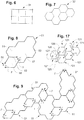
- FIG. 6 shows a possible rectangular basic shape 31 for single basins.
- This basic form 31 is, for example, in the embodiments according to Figure 1 to 5 as well as 11 to 14 implemented.
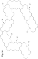
- FIG. 7 shows another basic shape 32, which is based on hexagonal primitives. Single basins of this basic form 32 can be joined in a form-fitting manner via the hexagonal subcontour of the outer wall arrangement (see FIG. 10 ).
- the single basin 51 after FIG. 8 is based, for example, on a joining together of hexagonal basic elements. Accordingly, the outer wall assembly 52 is formed like a jag.
- the inner wall assembly 53 is also oriented to the hexagonal basic pattern, wherein the second water receiving space 58 is hexagonal.
- the flow slot opening 55 and the transfer slot opening 56 are recessed in hexagonal wall sections.
- the calming zone 54 in the first water receiving space 57 also has a hexagonal shape.
- FIG. 9 shows a fish ladder, which from a plurality of joined individual pools 51 after FIG. 8 is erected.
- the individual basins 51 are joined in a form-fitting manner via the hexagonal subcontour of the outer wall arrangement 52.
- FIG. 17 again shows a fish ladder, which is built from a plurality of juxtaposed single basins 121, which are hexagonal.
- the single basin 121 thus has a hexagonal outer wall arrangement.
- Each single basin 121 further includes an inner wall assembly which divides the receiving space into first and second water receiving spaces 127, 128.
- the two water receiving chambers are connected to each other via a flow-through slot opening 125.
- a transfer slot opening 126 is also provided.
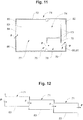
- FIGS. 11 to 14 show a further embodiment of a fish ladder with single basin 71st
- the single basin 71 ( FIG. 11 and 13 ) includes an outer wall assembly 72 having outer walls defining a receiving space 77, 78.
- the single basin 71 further includes an inner wall assembly 73 having inner walls which divide the receiving space 77, 78 into first and second water receiving spaces 77, 78.
- the two water receiving spaces 77, 78 are connected to each other via a flow-through opening 75 in the inner wall assembly 73, so that water can flow from the first water receiving space 77 into the second water receiving space 78.
- the outer wall arrangement 72 forms, upstream of the first water receiving space 77, an inlet opening 84, via which water can flow from an upstream, adjacent single basin 71 into the first water receiving space 77.
- the inner wall assembly 73 for forming the second water receiving space 78 is further configured such that in the first water receiving space 77, a pocket-shaped calming zone 74 is formed in which the inflow and outflow regions are arranged on the same side. In the calming zone 74 there is no flow, so that the fish can rest and recover in this zone.
- a transfer slot opening 76 is furthermore arranged in the wall arrangement, through which water can flow out of the second water receiving space 78 and out of the single basin 71.
- the transfer slot opening 76 is formed from a first wall section 79, which is part of the inner wall arrangement 73, and a second wall section 80, which is part of the outer wall arrangement 72.
- the two wall sections 79, 80 are arranged offset to one another, so that the water as it flows through the transfer slot opening 76 opposite the flow direction F through the flow slot opening 75 undergoes a change in direction.
- the outer wall assembly 72 further defines an outlet opening 91 through which water from the single basin can flow into a downstream, adjacent single basin 71.
- the outlet opening 91 is arranged downstream of the transfer slot opening 76, viewed in the flow direction F.
- the water flows, in particular at an angle, into the first water receiving space 77 of the single basin 71 located downstream. This prevents the water from flowing directly from the inlet port 84 to the flow-through port 75.
- the outer wall assembly 72 includes first connection surfaces 85, 86, 87 defining the inlet opening 84. Furthermore, the outer wall assembly 72 includes second connection surfaces 81, 82, 88 which define the outlet opening 91.
- the single basin 71 is connected via the first connecting surfaces 85, 86, 87 to the second connecting surfaces of an upstream, in particular identical, single basin. Furthermore, the single basin 71 is connected via the second connection surfaces 81, 82, 88 to the first connection surfaces of a downstream arranged, in particular identical, single basin.
- the connection can be made by means of screws.
- the individual basins 71 are according to FIG. 12 and 14 graduated to form a fishway.
- the water now flows in the direction of flow F through the transfer slot opening 76 of an upstream single basin 71 via the outlet flow opening 91 out of the single basin 71 and through the inlet opening 84 of the downstream immediately following single basin 71 in the first water receiving space 77 a.
- the inflowing water is deflected by the change in direction in the transfer slot opening 76 of the upstream single basin 71 to the calming zone 74 out.
- the water continues to flow from the first water receiving space 77 through the flow-through opening 75 into the second water receiving space 78. Via the transfer slot opening 76, the water flows in the manner described above from the single basin 71 into the downstream adjoining single basin 71 (see also FIG. 12 and 14 ).
- the present single basin 71 also includes a bottom 83. At the bottom 83 can also cross ribs as in the embodiment according to FIGS. 3 to 5 shown, may be arranged (not shown).
- FIGS. 15 and 16 show a further embodiment of a fish ladder with single basins 101.
- the individual basins 101 shown substantially correspond to those in the FIGS. 11 to 14
- the single basins 101 differ from the single basins 71 FIGS. 11 to 14 in that the flow-through slot 105 is V-shaped. Furthermore, the transfer slot 106 is wider and therefore has a larger flow area.
- FIG. 18 shows a further embodiment of a single basin 151.
- two such single basins 151 are shown interconnected.
- the same embodiment of the single basin 151 is also shown in FIGS. 19a-19b . 20a-20b and 21a-21c shown.
- the single basin 151 contains an outer wall arrangement 152 with outer walls, which delimit a receiving space 157, 158.
- the outer wall arrangement 152 forms upstream of the first water receiving space 157 an inlet opening 164 with a flow cross section (Q3), via which water can flow from an upstream adjacent single basin 151 into the first water receiving space 157.
- the single basin 151 further includes an inner wall assembly 153 which divide the receiving space into first and second water receiving spaces 157, 158.
- the two water receiving chambers 157, 158 are connected to each other via a flow-through slot opening 155 so that water can flow from the first water receiving space 157 into the second water receiving space 158.
- the second water receiving space 158 forms a water guide channel having an inflow-side first channel portion 159 with a flow cross-section (Q1) and an outflow-side second channel portion 160 having one with a flow area (Q2).
- the second channel section 160 is angled relative to the first channel section 159 by 45 ° to the below-mentioned calming zone 154.
- the flow area (Q2) of the second passage portion (160) is smaller than the flow area (Q1) of the first passage portion (159).
- the second channel section 160 forms a transfer slot opening 156, through which the water can flow out of the second water receiving space 158 and consequently out of the single basin 151.
- the water flows opposite the first channel section 159 at an angle through the inlet opening 164 into the first water receiving chamber 157 of the adjacent one Single basin 151 a. This prevents the water from flowing directly from the inlet port 164 to the flow slot port 155.
- the inner wall assembly 153 for forming the second water receiving space 158 is further configured such that the first water receiving space 157 forms a bag-like calming zone 154 in which the inflow and outflow regions are arranged on the same side. In the calming zone 154 there is no flow, so that the fish can rest and recover in this zone.
- the single basin 151 further includes a bottom 163 on which the wall assemblies 152, 153 are supported.
- the water then flows in the direction of flow F through the transfer slot opening 156 out of the upstream single basin 151 and out through the inlet opening 164 of the downstream immediately following single basin 151 into its first water receiving space 157.
- the inflowing water is deflected through the transfer slot opening 156 to the calming zone 154 and therefore also serves, in particular, as a lock flow or guide flow, which acts toward the calming zone 154.
- the water flows from the first water receiving space 157 through the flow slot opening 155 into the second water receiving space 158. Via the transfer slot opening 156, water flows from the single basin 151 into the downstream adjacent single basin 151 in the manner described above.
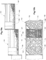
- FIG. 19a shows the single basin arrangement FIG. 18 in a cross-sectional view and the FIG. 19b in a top view.
- the bottom 163 of the single basins 151 is covered with a loose substrate 13.
- the single basin 151 contains stone-shaped retaining elements 166, which are stationary are connected to the floor 163.
- the loose substrate 13 is retained between the retaining elements 166.
- a further retaining element 167 in the form of a wire basket is also arranged immediately after the inlet opening 164.
- the wire basket picks up loose substrate and holds it back.
- the wire basket is designed such that it forms a flow ramp with the loose substrate 13. The flow ramp still terminates in the first receiving space 157 and merges into a horizontal sole formed by the substrate 13 retained by the retaining elements 166.
- the water flowing down the flow ramp at increased flow rate through the transfer slot opening 156 and the inlet opening 164 is calmed above the horizontal sole before it flows through the passage opening 155 into the second water receiving space 158.
- FIGS. 20a and 20b show a single basin arrangement in the lower estuary of the fish ladder.
- the upstream single basin 151 corresponds to the single basin after FIG. 18 or 19a-19b.
- the downstream single basin 151 ' corresponds to a lowermost single basin 151', which forms an estuarine area.
- the lowermost single basin 151 'lies directly on the ground or water body 181 and contains a permeable bottom 180.
- the permeable bottom 180 is formed by a wire mesh grid.
- water guide elements 168, 169 Downstream of the outer wall in the region of the transfer slot 156, water guide elements 168, 169 are screwed on the outside, which guide the water flowing through the transfer slot in the targeted area in a specific direction.
- the Figures 21a to 21c show various embodiments of water guide elements 168, 169, which deflect the water from the transfer slot opening in the mouth region in the direction of flow F as viewed to the left, to the right or straight ahead.
- FIG. 21b is the flow direction F of the water through the transfer slot opening 156 turned by 90 °.
- FIG. 22 shows an example of a self-supporting fish ladder with single basin 101 after FIGS. 15 and 16 , Only the top and bottom single basin 101 of the fish ladder is supported on the ground.
Landscapes
- Engineering & Computer Science (AREA)
- General Engineering & Computer Science (AREA)
- Life Sciences & Earth Sciences (AREA)
- Marine Sciences & Fisheries (AREA)
- Mechanical Engineering (AREA)
- Civil Engineering (AREA)
- Structural Engineering (AREA)
- Sewage (AREA)
- Farming Of Fish And Shellfish (AREA)
Claims (17)
- Bassin individuel (1, 51, 71, 101, 151) pour passe à poissons, doté d'un ensemble (2, 72, 152) de parois extérieures qui forme un espace de réception (7, 8; 77, 78; 127, 128; 157, 158) et une ouverture de transfert (6, 56, 76, 106, 156) en fente permettant le passage de l'eau entre des bassins individuels (71) voisins,
le bassin individuel (1, 51, 71, 101, 151) contenant un ensemble (3, 73, 153) de parois intérieures qui divise l'espace de réception (7, 8; 77, 78; 127, 128; 157, 158) en un premier et un deuxième espace de réception (7, 8; 77, 78; 127, 128; 157, 158), les espaces de réception (7, 8; 77, 78; 127, 128; 157, 158) étant reliés l'un à l'autre par une ouverture de passage (5, 55, 75, 105, 155) en fente permettant le passage de l'eau entre le premier espace de réception (7, 77, 127, 157) et le deuxième espace de réception (8, 78, 128, 158) espace de réception (8, 78, 128, 158), une zone (4, 54, 74, 154) de calmage d'eau étant formée dans le premier espace de réception (7, 77, 127, 157) en aval du deuxième espace de réception (8, 78, 128, 158),
caractérisé en ce que
le deuxième espace de réception (8,78, 128, 158) doté de l'ouverture de transfert (6, 56, 76, 106, 156) est configuré de telle sorte que l'eau qui s'écoule par l'ouverture de transfert (6, 56, 76, 106, 156) est introduite obliquement par rapport à la direction centrale d'écoulement dans un bassin individuel (1, 51, 71, 101, 151) aval voisin et est déviée en direction de la zone (4, 54, 74, 154) de calmage d'eau. - Bassin individuel selon la revendication 1, caractérisé en ce que le deuxième espace (158) de reprise d'eau contient un canal d'amenée d'eau présentant une première section de canal (159) située du côté de l'entrée et une deuxième section de canal (160) située du côté de la sortie, les deux sections de canal (159, 160) formant entre elles un angle.
- Bassin individuel selon la revendication 2, caractérisé en ce que la section transversale d'écoulement (Q2) de la deuxième section de canal (160) est plus petite que la section transversale d'écoulement (Q1) de la première section de canal (159) .
- Bassin individuel selon l'une des revendications 1 à 3, caractérisé en ce que l'ensemble (2, 72, 152) de parois extérieures forme en amont une ouverture (19, 84, 164) d'entrée vers le premier espace de réception (7, 8; 77, 78; 127, 128; 157, 158).
- Bassin individuel selon la revendication 4, caractérisé en ce que le deuxième espace de réception (8,78, 128, 158) est configuré de telle sorte que la direction de l'eau qui sort du deuxième espace de réception (8,78, 128, 158) par l'ouverture de transfert (6, 56, 76, 106, 156) forme un angle par rapport à un plan de passage formé par la section transversale de passage (Q3) de l'ouverture (19, 84, 164) d'entrée.
- Bassin individuel selon l'une des revendications 1 à 5, caractérisé en ce que l'ouverture de transfert (6, 56, 76, 106, 156) est formée par deux sections de paroi (9, 10; 79, 80) décalées l'une par rapport à l'autre.
- Bassin individuel selon l'une des revendications 1 à 6, caractérisé en ce que le bassin individuel (1, 51, 71, 101, 151) est réalisé en matière synthétique renforcée de fibres.
- Passe à poissons présentant plusieurs bassins individuels (1, 51, 71, 101, 151) selon l'une des revendications 1 à 7 qui sont reliées entre elles et formant un parcours de passage.
- Passe à poissons selon la revendication 8, caractérisée en ce que dans l'ensemble (72) de parois extérieures du bassin individuel (71) sont formées des parties de liaison avec des surfaces de liaison (81, 82, 88; 85, 86, 87), les bassins individuels (71) étant reliés à plat les uns aux autres, en particulier de manière libérable, par les surfaces de liaison (81, 82, 88; 85, 86, 87).
- Passe à poissons selon la revendication 9, caractérisée en ce que les bassins individuels (1, 51, 71, 101, 151) ont une forme polygonale de base et contiennent chacun deux premières parois extérieures non voisines l'une de l'autre et deux deuxièmes parois extérieures non voisines l'une de l'autre et qui s'étendent sous un angle par rapport aux premières parois extérieures, les deuxièmes parois extérieures étant configurées comme parois de liaison et deux bassins individuels (1, 51, 71, 101, 151) sont reliés l'un à l'autre par les deuxièmes parois extérieures.
- Passe à poissons selon la revendication 10, caractérisée en ce que l'ensemble (72) de parois extérieures forme en amont dans les parties de liaison (81, 82, 88; 85, 86, 87) une ouverture d'entrée (84) dans le premier espace (77) de reprise d'eau.
- Passe à poissons selon la revendication 11, caractérisée en ce que dans la direction d'écoulement (F), l'ensemble (72) de parois extérieures se raccorde à l'ouverture de transfert (76) en fente par une partie de liaison et une ouverture de sortie (91) disposée dans la partie de liaison, la section transversale de l'ouverture de sortie (91) étant plus grande que la section transversale de l'ouverture de transfert (76) en fente.
- Passe à poissons selon l'une des revendications 8 à 12, caractérisée en ce que deux bassins individuels (1, 51, 71, 101, 151) voisins forment chaque fois un gradin.
- Passe à poissons selon l'une des revendications 8 à 13, caractérisée en ce que la passe à poissons contient une structure de soutien configurée comme soubassement, en particulier un bâti inférieur sur lequel sont soutenus les bassins individuels.
- Passe à poissons selon la revendication 14, caractérisée en ce que la structure de soutien est soutenue sur le terrain par des pieds de soutien et est ancrée.
- Passe à poissons selon l'une des revendications 8 à 13, caractérisée en ce que les bassins individuels (101) sont reliés les uns aux autres pour former une structure autoportante.
- Passe à poissons selon l'une des revendications 8 à 16, caractérisée en ce que l'ouverture de transfert (156) en fente du bassin individuel (151') situé le plus bas en aval débouche dans une partie d'embouchure et en ce qu'au moins un élément (168, 169) de guidage d'eau au moyen duquel la direction d'écoulement (F) de l'eau qui s'écoule par l'ouverture de transfert (156) en fente peut être ajustée dans la zone d'embouchure, est disposé sur le bassin individuel (151').
Applications Claiming Priority (2)
| Application Number | Priority Date | Filing Date | Title |
|---|---|---|---|
| CH00813/14A CH709700A1 (de) | 2014-05-27 | 2014-05-27 | Fischaufstiegsanlage. |
| PCT/CH2015/000021 WO2015179990A1 (fr) | 2014-05-27 | 2015-02-20 | Passe à poissons |
Publications (2)
| Publication Number | Publication Date |
|---|---|
| EP3149247A1 EP3149247A1 (fr) | 2017-04-05 |
| EP3149247B1 true EP3149247B1 (fr) | 2018-09-26 |
Family
ID=52697175
Family Applications (1)
| Application Number | Title | Priority Date | Filing Date |
|---|---|---|---|
| EP15711038.8A Active EP3149247B1 (fr) | 2014-05-27 | 2015-02-20 | Passe à poissons |
Country Status (4)
| Country | Link |
|---|---|
| EP (1) | EP3149247B1 (fr) |
| CH (1) | CH709700A1 (fr) |
| DE (1) | DE212015000141U1 (fr) |
| WO (1) | WO2015179990A1 (fr) |
Families Citing this family (5)
| Publication number | Priority date | Publication date | Assignee | Title |
|---|---|---|---|---|
| EP3214225A1 (fr) * | 2016-03-02 | 2017-09-06 | MVM Holding GmbH | Dispositif de migration d'animaux aquatiques vers des barrières dans des eaux |
| CH714146A2 (de) | 2017-09-15 | 2019-03-15 | Wrh Walter Reist Holding Ag | Wasserführungseinheit für eine Fischaufstiegsanlage und Fischaufstiegsanlage mit einer Mehrzahl von miteinander verbundenden Wasserführungseinheiten. |
| DE102019004859A1 (de) * | 2019-07-03 | 2021-01-07 | Guido Becker | Fischaufstiegshilfe |
| CN110894719B (zh) * | 2019-11-25 | 2025-01-24 | 四川大学 | 一种隔膜式鱼道 |
| CN115961597B (zh) * | 2023-03-17 | 2023-05-16 | 四川省水利科学研究院 | 一种鱼道灌溉设备 |
Family Cites Families (9)
| Publication number | Priority date | Publication date | Assignee | Title |
|---|---|---|---|---|
| CA375421A (fr) * | 1938-07-26 | G. Hurst Frederick | Passage a poissons | |
| JPH11315528A (ja) * | 1998-05-01 | 1999-11-16 | Hokuetsu:Kk | 水路式魚道ブロックおよび水路式魚道 |
| JP3721455B2 (ja) * | 2002-06-12 | 2005-11-30 | 滋賀県 | 魚類遡上構造及びそれに用いる水路部材 |
| KR100658432B1 (ko) * | 2004-12-27 | 2006-12-15 | 강남 | 어도블록 |
| DE202005010752U1 (de) | 2005-07-08 | 2005-09-22 | Hammerl, Rudolf, Dipl.-Ing. | Technische Fischaufstiegshilfe aus einzelnen Trögen zusammengesetzt |
| DE202005019792U1 (de) * | 2005-12-19 | 2006-03-23 | Peters, Hans Wilhelm | Mäandrierender Fischpass |
| AT9955U1 (de) * | 2007-06-21 | 2008-06-15 | Sw Umwelttechnik Oesterreich G | Anordnung an fliessenden gewässern |
| AT507195B1 (de) * | 2008-08-22 | 2010-03-15 | Kirchdorfer Fertigteilholding | Organismenwanderanlage |
| JP5576816B2 (ja) * | 2011-03-11 | 2014-08-20 | 日鐵住金建材株式会社 | 鋼製竪形魚道及びその構築方法 |
-
2014
- 2014-05-27 CH CH00813/14A patent/CH709700A1/de not_active Application Discontinuation
-
2015
- 2015-02-20 WO PCT/CH2015/000021 patent/WO2015179990A1/fr not_active Ceased
- 2015-02-20 DE DE212015000141.5U patent/DE212015000141U1/de not_active Expired - Lifetime
- 2015-02-20 EP EP15711038.8A patent/EP3149247B1/fr active Active
Non-Patent Citations (1)
| Title |
|---|
| None * |
Also Published As
| Publication number | Publication date |
|---|---|
| EP3149247A1 (fr) | 2017-04-05 |
| WO2015179990A1 (fr) | 2015-12-03 |
| DE212015000141U1 (de) | 2017-07-26 |
| CH709700A1 (de) | 2015-11-30 |
Similar Documents
| Publication | Publication Date | Title |
|---|---|---|
| EP0901540B1 (fr) | Echelle a poissons | |
| WO2015179990A1 (fr) | Passe à poissons | |
| EP2098640A2 (fr) | Dispositif de descente d'anguilles sur des bâtiments maritimes | |
| DE10331596B4 (de) | Fischpass | |
| DE2603018B2 (de) | Behälter für Pflanzen | |
| EP3456884A2 (fr) | Installation de remontée piscicole | |
| DE3539832A1 (de) | Oekologisches schutzdeckwerk fuer fliessende gewaesser | |
| DE202005019792U1 (de) | Mäandrierender Fischpass | |
| AT9955U1 (de) | Anordnung an fliessenden gewässern | |
| DE102009044069B4 (de) | Fischaufstiegsanlage zur Überwindung eines Wanderhindernisses in einem Fließgewässer | |
| AT520908B1 (de) | Vorrichtung zur Wanderung von Wassertieren an Barrieren in Gewässern | |
| DE102016111780A1 (de) | Floßartige Vorrichtung | |
| EP2441890A1 (fr) | Passage à poissons à méandre pour bateau | |
| DE102010037926A1 (de) | Wasserkraftanlage | |
| DE102013201427A1 (de) | Fischaufstiegsvorrichtung sowie Verfahren zu dessen Betrieb | |
| EP3214225A1 (fr) | Dispositif de migration d'animaux aquatiques vers des barrières dans des eaux | |
| DE102010021606A1 (de) | Vorrichtung zur Habitaterschließung im Unterwasserbereich eines Offshore-Bauwerks | |
| EP3173530A1 (fr) | Dispositif de migration d'animaux aquatiques vers des barrières dans des eaux | |
| AT516339A2 (de) | Wehranlage, insbesondere Kiesschleuse | |
| EP2918727B1 (fr) | Corps de construction, en particulier à partir d'éléments préfabriqués, pour une petite centrale | |
| AT514687A4 (de) | Sohlanbindung und Lockströmung bei Fischaufstiegsschnecken | |
| AT12581U1 (de) | Anordnung an fliessenden gewässern | |
| DE10043589B4 (de) | Künstliches Bachbett | |
| EP4339375A1 (fr) | Dispositif pour la migration d'animaux aquatiques | |
| EP1911883A2 (fr) | Pont pour petits animaux destiné à des croisements de voies de communication d'eaux |
Legal Events
| Date | Code | Title | Description |
|---|---|---|---|
| STAA | Information on the status of an ep patent application or granted ep patent |
Free format text: STATUS: THE INTERNATIONAL PUBLICATION HAS BEEN MADE |
|
| PUAI | Public reference made under article 153(3) epc to a published international application that has entered the european phase |
Free format text: ORIGINAL CODE: 0009012 |
|
| STAA | Information on the status of an ep patent application or granted ep patent |
Free format text: STATUS: REQUEST FOR EXAMINATION WAS MADE |
|
| 17P | Request for examination filed |
Effective date: 20161123 |
|
| AK | Designated contracting states |
Kind code of ref document: A1 Designated state(s): AL AT BE BG CH CY CZ DE DK EE ES FI FR GB GR HR HU IE IS IT LI LT LU LV MC MK MT NL NO PL PT RO RS SE SI SK SM TR |
|
| AX | Request for extension of the european patent |
Extension state: BA ME |
|
| DAX | Request for extension of the european patent (deleted) | ||
| STAA | Information on the status of an ep patent application or granted ep patent |
Free format text: STATUS: EXAMINATION IS IN PROGRESS |
|
| 17Q | First examination report despatched |
Effective date: 20180222 |
|
| GRAP | Despatch of communication of intention to grant a patent |
Free format text: ORIGINAL CODE: EPIDOSNIGR1 |
|
| STAA | Information on the status of an ep patent application or granted ep patent |
Free format text: STATUS: GRANT OF PATENT IS INTENDED |
|
| INTG | Intention to grant announced |
Effective date: 20180502 |
|
| GRAS | Grant fee paid |
Free format text: ORIGINAL CODE: EPIDOSNIGR3 |
|
| GRAA | (expected) grant |
Free format text: ORIGINAL CODE: 0009210 |
|
| STAA | Information on the status of an ep patent application or granted ep patent |
Free format text: STATUS: THE PATENT HAS BEEN GRANTED |
|
| AK | Designated contracting states |
Kind code of ref document: B1 Designated state(s): AL AT BE BG CH CY CZ DE DK EE ES FI FR GB GR HR HU IE IS IT LI LT LU LV MC MK MT NL NO PL PT RO RS SE SI SK SM TR |
|
| REG | Reference to a national code |
Ref country code: GB Ref legal event code: FG4D Free format text: NOT ENGLISH |
|
| REG | Reference to a national code |
Ref country code: CH Ref legal event code: EP |
|
| REG | Reference to a national code |
Ref country code: AT Ref legal event code: REF Ref document number: 1046186 Country of ref document: AT Kind code of ref document: T Effective date: 20181015 |
|
| REG | Reference to a national code |
Ref country code: IE Ref legal event code: FG4D Free format text: LANGUAGE OF EP DOCUMENT: GERMAN |
|
| REG | Reference to a national code |
Ref country code: DE Ref legal event code: R096 Ref document number: 502015006082 Country of ref document: DE |
|
| REG | Reference to a national code |
Ref country code: CH Ref legal event code: NV Representative=s name: FREI PATENTANWALTSBUERO AG, CH |
|
| REG | Reference to a national code |
Ref country code: NL Ref legal event code: MP Effective date: 20180926 |
|
| PG25 | Lapsed in a contracting state [announced via postgrant information from national office to epo] |
Ref country code: FI Free format text: LAPSE BECAUSE OF FAILURE TO SUBMIT A TRANSLATION OF THE DESCRIPTION OR TO PAY THE FEE WITHIN THE PRESCRIBED TIME-LIMIT Effective date: 20180926 Ref country code: LT Free format text: LAPSE BECAUSE OF FAILURE TO SUBMIT A TRANSLATION OF THE DESCRIPTION OR TO PAY THE FEE WITHIN THE PRESCRIBED TIME-LIMIT Effective date: 20180926 Ref country code: RS Free format text: LAPSE BECAUSE OF FAILURE TO SUBMIT A TRANSLATION OF THE DESCRIPTION OR TO PAY THE FEE WITHIN THE PRESCRIBED TIME-LIMIT Effective date: 20180926 Ref country code: SE Free format text: LAPSE BECAUSE OF FAILURE TO SUBMIT A TRANSLATION OF THE DESCRIPTION OR TO PAY THE FEE WITHIN THE PRESCRIBED TIME-LIMIT Effective date: 20180926 Ref country code: GR Free format text: LAPSE BECAUSE OF FAILURE TO SUBMIT A TRANSLATION OF THE DESCRIPTION OR TO PAY THE FEE WITHIN THE PRESCRIBED TIME-LIMIT Effective date: 20181227 Ref country code: NO Free format text: LAPSE BECAUSE OF FAILURE TO SUBMIT A TRANSLATION OF THE DESCRIPTION OR TO PAY THE FEE WITHIN THE PRESCRIBED TIME-LIMIT Effective date: 20181226 Ref country code: BG Free format text: LAPSE BECAUSE OF FAILURE TO SUBMIT A TRANSLATION OF THE DESCRIPTION OR TO PAY THE FEE WITHIN THE PRESCRIBED TIME-LIMIT Effective date: 20181226 |
|
| REG | Reference to a national code |
Ref country code: LT Ref legal event code: MG4D |
|
| PG25 | Lapsed in a contracting state [announced via postgrant information from national office to epo] |
Ref country code: LV Free format text: LAPSE BECAUSE OF FAILURE TO SUBMIT A TRANSLATION OF THE DESCRIPTION OR TO PAY THE FEE WITHIN THE PRESCRIBED TIME-LIMIT Effective date: 20180926 Ref country code: HR Free format text: LAPSE BECAUSE OF FAILURE TO SUBMIT A TRANSLATION OF THE DESCRIPTION OR TO PAY THE FEE WITHIN THE PRESCRIBED TIME-LIMIT Effective date: 20180926 Ref country code: AL Free format text: LAPSE BECAUSE OF FAILURE TO SUBMIT A TRANSLATION OF THE DESCRIPTION OR TO PAY THE FEE WITHIN THE PRESCRIBED TIME-LIMIT Effective date: 20180926 |
|
| REG | Reference to a national code |
Ref country code: CH Ref legal event code: PUE Owner name: HERZOG INGENIEURE AG, CH Free format text: FORMER OWNER: WRH WALTER REIST HOLDING AG, CH |
|
| PG25 | Lapsed in a contracting state [announced via postgrant information from national office to epo] |
Ref country code: ES Free format text: LAPSE BECAUSE OF FAILURE TO SUBMIT A TRANSLATION OF THE DESCRIPTION OR TO PAY THE FEE WITHIN THE PRESCRIBED TIME-LIMIT Effective date: 20180926 Ref country code: NL Free format text: LAPSE BECAUSE OF FAILURE TO SUBMIT A TRANSLATION OF THE DESCRIPTION OR TO PAY THE FEE WITHIN THE PRESCRIBED TIME-LIMIT Effective date: 20180926 Ref country code: RO Free format text: LAPSE BECAUSE OF FAILURE TO SUBMIT A TRANSLATION OF THE DESCRIPTION OR TO PAY THE FEE WITHIN THE PRESCRIBED TIME-LIMIT Effective date: 20180926 Ref country code: CZ Free format text: LAPSE BECAUSE OF FAILURE TO SUBMIT A TRANSLATION OF THE DESCRIPTION OR TO PAY THE FEE WITHIN THE PRESCRIBED TIME-LIMIT Effective date: 20180926 Ref country code: PL Free format text: LAPSE BECAUSE OF FAILURE TO SUBMIT A TRANSLATION OF THE DESCRIPTION OR TO PAY THE FEE WITHIN THE PRESCRIBED TIME-LIMIT Effective date: 20180926 Ref country code: IS Free format text: LAPSE BECAUSE OF FAILURE TO SUBMIT A TRANSLATION OF THE DESCRIPTION OR TO PAY THE FEE WITHIN THE PRESCRIBED TIME-LIMIT Effective date: 20190126 Ref country code: EE Free format text: LAPSE BECAUSE OF FAILURE TO SUBMIT A TRANSLATION OF THE DESCRIPTION OR TO PAY THE FEE WITHIN THE PRESCRIBED TIME-LIMIT Effective date: 20180926 |
|
| PGFP | Annual fee paid to national office [announced via postgrant information from national office to epo] |
Ref country code: IT Payment date: 20190225 Year of fee payment: 5 Ref country code: DE Payment date: 20190219 Year of fee payment: 5 |
|
| PG25 | Lapsed in a contracting state [announced via postgrant information from national office to epo] |
Ref country code: SK Free format text: LAPSE BECAUSE OF FAILURE TO SUBMIT A TRANSLATION OF THE DESCRIPTION OR TO PAY THE FEE WITHIN THE PRESCRIBED TIME-LIMIT Effective date: 20180926 Ref country code: PT Free format text: LAPSE BECAUSE OF FAILURE TO SUBMIT A TRANSLATION OF THE DESCRIPTION OR TO PAY THE FEE WITHIN THE PRESCRIBED TIME-LIMIT Effective date: 20190126 Ref country code: SM Free format text: LAPSE BECAUSE OF FAILURE TO SUBMIT A TRANSLATION OF THE DESCRIPTION OR TO PAY THE FEE WITHIN THE PRESCRIBED TIME-LIMIT Effective date: 20180926 |
|
| PGFP | Annual fee paid to national office [announced via postgrant information from national office to epo] |
Ref country code: FR Payment date: 20190218 Year of fee payment: 5 |
|
| REG | Reference to a national code |
Ref country code: DE Ref legal event code: R097 Ref document number: 502015006082 Country of ref document: DE |
|
| PG25 | Lapsed in a contracting state [announced via postgrant information from national office to epo] |
Ref country code: DK Free format text: LAPSE BECAUSE OF FAILURE TO SUBMIT A TRANSLATION OF THE DESCRIPTION OR TO PAY THE FEE WITHIN THE PRESCRIBED TIME-LIMIT Effective date: 20180926 |
|
| PLBE | No opposition filed within time limit |
Free format text: ORIGINAL CODE: 0009261 |
|
| STAA | Information on the status of an ep patent application or granted ep patent |
Free format text: STATUS: NO OPPOSITION FILED WITHIN TIME LIMIT |
|
| 26N | No opposition filed |
Effective date: 20190627 |
|
| GBPC | Gb: european patent ceased through non-payment of renewal fee |
Effective date: 20190220 |
|
| PG25 | Lapsed in a contracting state [announced via postgrant information from national office to epo] |
Ref country code: MC Free format text: LAPSE BECAUSE OF FAILURE TO SUBMIT A TRANSLATION OF THE DESCRIPTION OR TO PAY THE FEE WITHIN THE PRESCRIBED TIME-LIMIT Effective date: 20180926 Ref country code: LU Free format text: LAPSE BECAUSE OF NON-PAYMENT OF DUE FEES Effective date: 20190220 Ref country code: SI Free format text: LAPSE BECAUSE OF FAILURE TO SUBMIT A TRANSLATION OF THE DESCRIPTION OR TO PAY THE FEE WITHIN THE PRESCRIBED TIME-LIMIT Effective date: 20180926 |
|
| REG | Reference to a national code |
Ref country code: BE Ref legal event code: MM Effective date: 20190228 |
|
| REG | Reference to a national code |
Ref country code: IE Ref legal event code: MM4A |
|
| PG25 | Lapsed in a contracting state [announced via postgrant information from national office to epo] |
Ref country code: GB Free format text: LAPSE BECAUSE OF NON-PAYMENT OF DUE FEES Effective date: 20190220 Ref country code: IE Free format text: LAPSE BECAUSE OF NON-PAYMENT OF DUE FEES Effective date: 20190220 |
|
| PG25 | Lapsed in a contracting state [announced via postgrant information from national office to epo] |
Ref country code: BE Free format text: LAPSE BECAUSE OF NON-PAYMENT OF DUE FEES Effective date: 20190228 |
|
| PG25 | Lapsed in a contracting state [announced via postgrant information from national office to epo] |
Ref country code: TR Free format text: LAPSE BECAUSE OF FAILURE TO SUBMIT A TRANSLATION OF THE DESCRIPTION OR TO PAY THE FEE WITHIN THE PRESCRIBED TIME-LIMIT Effective date: 20180926 |
|
| PG25 | Lapsed in a contracting state [announced via postgrant information from national office to epo] |
Ref country code: MT Free format text: LAPSE BECAUSE OF FAILURE TO SUBMIT A TRANSLATION OF THE DESCRIPTION OR TO PAY THE FEE WITHIN THE PRESCRIBED TIME-LIMIT Effective date: 20180926 |
|
| REG | Reference to a national code |
Ref country code: DE Ref legal event code: R119 Ref document number: 502015006082 Country of ref document: DE |
|
| PG25 | Lapsed in a contracting state [announced via postgrant information from national office to epo] |
Ref country code: FR Free format text: LAPSE BECAUSE OF NON-PAYMENT OF DUE FEES Effective date: 20200229 Ref country code: DE Free format text: LAPSE BECAUSE OF NON-PAYMENT OF DUE FEES Effective date: 20200901 |
|
| REG | Reference to a national code |
Ref country code: AT Ref legal event code: MM01 Ref document number: 1046186 Country of ref document: AT Kind code of ref document: T Effective date: 20200220 |
|
| PG25 | Lapsed in a contracting state [announced via postgrant information from national office to epo] |
Ref country code: CY Free format text: LAPSE BECAUSE OF FAILURE TO SUBMIT A TRANSLATION OF THE DESCRIPTION OR TO PAY THE FEE WITHIN THE PRESCRIBED TIME-LIMIT Effective date: 20180926 Ref country code: AT Free format text: LAPSE BECAUSE OF NON-PAYMENT OF DUE FEES Effective date: 20200220 |
|
| PG25 | Lapsed in a contracting state [announced via postgrant information from national office to epo] |
Ref country code: HU Free format text: LAPSE BECAUSE OF FAILURE TO SUBMIT A TRANSLATION OF THE DESCRIPTION OR TO PAY THE FEE WITHIN THE PRESCRIBED TIME-LIMIT; INVALID AB INITIO Effective date: 20150220 |
|
| PG25 | Lapsed in a contracting state [announced via postgrant information from national office to epo] |
Ref country code: IT Free format text: LAPSE BECAUSE OF NON-PAYMENT OF DUE FEES Effective date: 20200220 |
|
| PG25 | Lapsed in a contracting state [announced via postgrant information from national office to epo] |
Ref country code: MK Free format text: LAPSE BECAUSE OF FAILURE TO SUBMIT A TRANSLATION OF THE DESCRIPTION OR TO PAY THE FEE WITHIN THE PRESCRIBED TIME-LIMIT Effective date: 20180926 |
|
| REG | Reference to a national code |
Ref country code: CH Ref legal event code: U11 Free format text: ST27 STATUS EVENT CODE: U-0-0-U10-U11 (AS PROVIDED BY THE NATIONAL OFFICE) Effective date: 20260301 |
|
| PGFP | Annual fee paid to national office [announced via postgrant information from national office to epo] |
Ref country code: CH Payment date: 20260301 Year of fee payment: 12 |