EP0901819B1 - Dispositif avec récipient de prélèvement - Google Patents
Dispositif avec récipient de prélèvement Download PDFInfo
- Publication number
- EP0901819B1 EP0901819B1 EP98115132A EP98115132A EP0901819B1 EP 0901819 B1 EP0901819 B1 EP 0901819B1 EP 98115132 A EP98115132 A EP 98115132A EP 98115132 A EP98115132 A EP 98115132A EP 0901819 B1 EP0901819 B1 EP 0901819B1
- Authority
- EP
- European Patent Office
- Prior art keywords
- cylindrical sidewall
- assembly
- container
- tubular sleeve
- sidewall
- Prior art date
- Legal status (The legal status is an assumption and is not a legal conclusion. Google has not performed a legal analysis and makes no representation as to the accuracy of the status listed.)
- Expired - Lifetime
Links
Images




Classifications
-
- B—PERFORMING OPERATIONS; TRANSPORTING
- B01—PHYSICAL OR CHEMICAL PROCESSES OR APPARATUS IN GENERAL
- B01L—CHEMICAL OR PHYSICAL LABORATORY APPARATUS FOR GENERAL USE
- B01L3/00—Containers or dishes for laboratory use, e.g. laboratory glassware; Droppers
- B01L3/50—Containers for the purpose of retaining a material to be analysed, e.g. test tubes
- B01L3/508—Rigid containers without fluid transport within
- B01L3/5082—Test tubes per se
-
- B—PERFORMING OPERATIONS; TRANSPORTING
- B65—CONVEYING; PACKING; STORING; HANDLING THIN OR FILAMENTARY MATERIAL
- B65G—TRANSPORT OR STORAGE DEVICES, e.g. CONVEYORS FOR LOADING OR TIPPING, SHOP CONVEYOR SYSTEMS OR PNEUMATIC TUBE CONVEYORS
- B65G2201/00—Indexing codes relating to handling devices, e.g. conveyors, characterised by the type of product or load being conveyed or handled
- B65G2201/02—Articles
- B65G2201/0235—Containers
- B65G2201/0261—Puck as article support
-
- Y—GENERAL TAGGING OF NEW TECHNOLOGICAL DEVELOPMENTS; GENERAL TAGGING OF CROSS-SECTIONAL TECHNOLOGIES SPANNING OVER SEVERAL SECTIONS OF THE IPC; TECHNICAL SUBJECTS COVERED BY FORMER USPC CROSS-REFERENCE ART COLLECTIONS [XRACs] AND DIGESTS
- Y10—TECHNICAL SUBJECTS COVERED BY FORMER USPC
- Y10S—TECHNICAL SUBJECTS COVERED BY FORMER USPC CROSS-REFERENCE ART COLLECTIONS [XRACs] AND DIGESTS
- Y10S220/00—Receptacles
- Y10S220/918—Spacing element for separating the walls of a spaced-wall container
- Y10S220/921—Spacing element of unitary construction with one wall
Definitions
- This invention relates to a specimen collection container assembly and more particularly to a collection container for collecting biological fluid specimens where a small quantity of fluid may be collected and retained in the container while maintaining a container size sufficient to be easily accommodated and/or compatible with standard clinical equipment and instrumentation.
- Blood samples and other biological fluid specimens are routinely taken and analyzed in hospital and clinical situations for various medical purposes. Collection, handling and testing of these samples typically requires the use of various medical testing instruments. As the blood and fluid specimens are usually collected in a standard sized collection tube, the medical instruments used to test the samples are designed to accommodate these standard sized collection tubes.
- Conventional blood collection tubes used in most clinical situations are elongated cylindrical containers having one end closed by a semi-spherical or rounded portion and an opposed open end. The open end may be sealed by a resilient cap or stopper.
- the tube defines a collection interior which collects and holds the blood sample.
- the most common size of these blood collection tubes are designed to accommodate approximately 10 ml of blood or other biological fluid samples.
- Illustrative of such blood collection tubes is the VACUTAINER® brand blood collection tube sold by Becton, Dickinson and Company, 1 Becton Drive, Franklin Lakes, NJ (registered trademark of Becton, Dickinson and Company).
- a phlebotomist or other medical technician typically obtains a specimen of the patient's blood in the tube by techniques well known in the art.
- the tube is then appropriately labeled and transferred from the site of collection to a laboratory or other location where the contents of the tube are analyzed.
- the tube may be supported by various medical instruments.
- the plasma or serum derived therefrom is processed and analyzed either manually, semiautomatically or automatically. In some cases, the specimen must first be dispensed from the collection tube to a sample test tube or cuvette.
- specimen containers such as those incorporating a "false bottom” have been proposed to achieve decreased volume capacity in conjunction with standard external dimensions.
- these various specimen containers are not compatible with standard clinical equipment and instrumentation due to their design.
- these specimen containers have false bottoms with a generally flat, planar bottom end and a circular shaped opening.
- specimen containers include partial-draw tubes which have standard external dimensions with partial evacuation so that blood fills only a portion of the internal volume.
- partial-draw tubes exhibit a reduction in the draw rate of a sample which reduces the collection efficacy of such tubes.
- partial-draw tubes may result in an inconsistent fill volume which may alter test results.
- it is difficult to determine accurate sample quantities with such partial-draw tubes because the slow rate of sample draw is not consistently measurable.
- a collection assembly corresponding to the introductory part of claim 1, is disclosed in US-A-5,653,686.
- This document describes a transfer device for transferring fluids between closed vials.
- the device has two tubes that are separated by a wall through which extends a fluid transfer needle.
- a first vial containing a sample is, stopper first, inserted into a first tube until seated on an exposed end of the transfer needle.
- a second vial, the transfer vial is, stopper first, then inserted into the second tube until seated on the opposite exposed end of the transfer needle.
- Both vials are generally cylindrical and they have only one side wall.
- the container comprises a first cylindrical sidewall, a second cylindrical sidewall and a third cylindrical sidewall, whereby said first cylindrical sidewall extends from said rim towards said second cylindrical sidewall and said second cylindrical sidewall extends towards said third cylindrical sidewall.
- the present invention is a collection assembly comprising a container and a tubular sleeve.
- the container preferably comprises an open top portion, a closed bottom portion and a sidewall extending from the open top portion to the closed bottom portion.
- the tubular sleeve preferably comprises opposing open portions identified as an open top portion, and an open bottom portion and a cylindrical sidewall extending between the opposing open ends. Most preferably, the container fits within the tubular sleeve.
- the external diameter of the container is less than the internal diameter of the tubular sleeve.
- the external dimensions of the container are less than the external dimensions of the tubular sleeve.
- the tubular sleeve of the assembly provides a means for allowing the container to be modified so as to be compatible with standard clinical equipment and instrumentation.
- the tubular sleeve is removably secured to the container whereby the container is inserted into the tubular sleeve by force friction or an interference fit.
- the tubular sleeve may be the same or different material than the container and may be integral with the container or may be a discrete member so as to be reusable.
- the tubular sleeve is removably unsecured from the container whereby the user slightly twists or pulls the container and the tubular sleeve in opposite rotating directions thereby removing the tubular sleeve from the container.
- the tubular sleeve then can be used again.
- the assembly may further comprise a closure such as a cap or a stopper at the open end of the container.
- the external dimensions of the assembly which includes the container and the tubular sleeve are about the same or substantially the same as a standard-sized or full draw blood collection container assembly.
- Standard-sized full draw blood collection containers have an outer diameter of about 13 to about 16 millimeters, a length of about 75 to about 100 millimeters and an internal volume of about 6 to 10 milliliters.
- the assembly of the present invention can be either evacuated or non-evacuated.
- the assembly is made from polyethylene terephthalate, polypropylene, polyethylene, polyethylene napthalate polyvinyl chloride or copolymers thereof.
- An advantage of the assembly of the present invention is that it provides a full-draw blood collection container assembly having a reduced internal volume but with external dimensions about the same or substantially the same as a standard-sized blood collection container assembly.
- the assembly of the present invention has a standard draw rate as compared to partial draw rate tubes.
- a further advantage of the assembly of the present invention is that it provides a specimen collection container which is universally compatible with various clinical equipment and instrumentation.
- the assembly of the present invention may be easily handled by equipment configured to handle standard-sized blood collection tubes having standard external dimensions.
- the assembly of the present invention provides a blood collection container having full draw external dimensions but with a reduced internal volume as compared to standard-sized full draw blood collection tubes or standard-sized partial draw blood collection tubes.
- the assembly of the present invention therefore addresses the need for a full-draw low-volume blood collection container assembly that presents the external dimensions of a standard-sized blood collection tube.
- the assembly of the present invention may be used to reliably collect small samples of blood or biological fluids and to maintain the integrity of the samples during storage and transport as compared to using standard-sized blood collection tubes.
- the assembly of the present invention can also be accommodated by standard-sized blood collection, transportation, storage, and diagnostic equipment.
- the assembly of the present invention may be used to reliably collect small samples of blood or biological fluids without being under partial pressure.
- the assembly of the present invention is also compatible with existing instrumentation, labels, and bar code readers and obviates the need for new instrumentation and handling devices or procedures that would be required for smaller or varying sized tubes or tubes with flat planar bottoms.
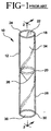
- FIGS. 1 and 2 show a false bottom specimen container 10 of the prior art, having a sidewall 12 having an outer surface 14 and an inner surface 16 .
- Sidewall 12 extends from an upper portion 18 to a lower portion 20 .
- Upper portion 18 includes an open end 22 and a rim 24 .
- Lower portion 20 comprises a closed bottom end 26 .
- An annular skirt 28 extends from lower portion 20 and outer surface 14 to a flat planar bottom end 30 to define an open false bottom area 36 .
- Interior volume 34 extends between rim 24 and closed bottom end 26 .
- FIGS. 3 and 4 show a typical standard sized blood collection tube 40 , having a sidewall 42 extending from an open end rim 44 to a closed end 46 and an interior area 48 .
- Sidewall 42 has an inner wall surface 50 and an outer wall surface 52 .
- a closure 54 may be on the open end rim 44 of tube 40 .
- Tube 40 is most preferably a standard-sized blood collection tube having an outer diameter A of about 13 millimeters, a length B of about 75 millimeters and an internal volume 48 of about 10 milliliters as measured from rim 44 to closed end 46 .
- Interior area 48 is typically maintained at a lower-than-atmospheric internal pressure so that when a blood collection probe penetrates through the closure placing interior area 48 in communication with the circulatory system of a patient, the 48 will draw blood from the patient into the tube.
- Tube 40 may be described as a full-draw evacuated blood collection tube because the internal pressure of interior area 48 is low enough to draw a volume of blood substantially equal to the volume of interior area 48 .
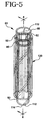
- FIGS. 5 and 6 show the preferred embodiment of the present invention, assembly 60 .
- Assembly 60 comprises a container 80 and a tubular sleeve 120 .
- Container 80 comprises an open end portion 110 and a closed end portion 112 whereby closed end portion 112 has a semi-spherical wall end 114 .
- Container 80 comprises a first cylindrical sidewall 92 having an outer surface 84 and an inner surface 86 .
- First cylindrical sidewall 92 extends from a rim 85 towards a second cylindrical sidewall 90 .
- a shoulder connects first cylindrical sidewall 92 and second cylindrical sidewall 90 .
- Second cylindrical sidewall 90 has a smaller internal and external diameter than first cylindrical sidewall 92 .
- Second cylindrical sidewall 90 comprises an outer surface 94 and an inner surface 96 .
- Second cylindrical sidewall 90 extends towards a third cylindrical sidewall 98 .
- a shoulder 100 connects second cylindrical sidewall 90 and third cylindrical sidewall 98 .
- Third cylindrical sidewall 98 has a smaller internal and external diameter than second cylindrical sidewall 90 .
- Third cylindrical sidewall 98 extends to closed end portion 112 .
- Third cylindrical sidewall 98 comprises an outer surface 102 and
- An interior volume 106 extends between rim 85 and semi-spherical wall end 114 .
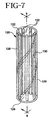
- tubular sleeve 120 includes an open top portion 122 , an open bottom portion 124 , and a sidewall 126 extending from the top portion to the bottom portion. It is within the purview of this invention that there is no distinction between top and bottom portions of the tubular sleeve other than they are opposing ends.
- Sidewall 126 of tubular sleeve 120 includes an outerwall surface 128 and an inner wall surface 130 .
- a plurality of ribs 132 are associated on inner wall surface 130 .
- Ribs 132 assist with the removable secure fit of the tubular sleeve and the container.
- ribs 132 are not on the tubular sleeve and that the external dimensions of the container and internal dimensions of the tubular sleeve will permit an interference fit.
- Tubular sleeve 120 provides means for converting the container to substantially the same external dimensions as a standard-sized blood collection tube.
- assembly 60 has an outer diameter C of about 13 millimeters, as measured by the external dimensions of tubular sleeve 120 , a length D of about 75 millimeters, as measured from rim 85 to semi-spherical wall end 114 , and an interior volume 106 of about 1 to 3 milliliters.
- the external diameter C of tubular sleeve 120 is about 13 millimeters. It is within the purview of this invention that assembly 60 may have an outer diameter of about 13 to about 16 millimeters, a length of about 75 to about 100 millimeters and an interior volume of about 1 to about 3 milliliters.
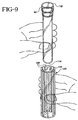
- tubular sleeve 120 is readily compatible with container 80 .
- Container 80 may be inserted into tubular sleeve 120 through either open top portion 122 or open bottom portion 124 .
- inner wall surface 130 or ribs 132 of tubular sleeve 120 mates or fits with outer surface 94 of second cylindrical sidewall of container 80 whereby an interference fit or frictional engagement between them holds container 80 within tubular sleeve 120 .
- the tubular sleeve may be removed from the assembly whereby the user slightly twists or pulls the container and the tubular sleeve in opposite directions thereby removing the tubular sleeve from the container.
- the tubular sleeve can then be reused.
- the length of container 80 and tubular sleeve 120 may be varied so that closed end portion 112 of container 80 may be located within tubular sleeve 120 or extend through the one of the opposing open ends 122 or 124 of tubular sleeve 120 .
- Tubular sleeve 120 may be formed from a thermoformed plastic such as thermoplastic elastomer, polyvinylchloride, polyurethane, polyethylene or polypropylene.
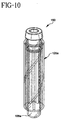
- FIG. 10 includes many components which are substantially identical to the components of FIGS. 5-6. Accordingly, similar components performing similar functions will be numbered identically to those components of FIGS. 5-6, except that a suffix "a" will be used to identify the similar components in FIG. 10.
- a further embodiment of the invention is assembly 150 which includes a closure 160 .
- FIG. 10 may be evacuated or non-evacuated.
- assembly 150 When assembly 150 is evacuated, interior volume 106a is maintained at a lower-than-atmospheric internal pressure so that when a blood collection probe penetrates through the closure placing interior volume 106a in communication with the circulatory system of a patient, the lower-than-atmospheric pressure of interior volume 106a will draw blood from the patient into the tube.
- Assembly 150 may be described as a full-draw evacuated blood collection tube because the internal pressure of interior volume 106a is low enough to draw a volume of blood substantially equal to the volume of interior volume 106a .
Landscapes
- Health & Medical Sciences (AREA)
- Chemical & Material Sciences (AREA)
- Analytical Chemistry (AREA)
- General Health & Medical Sciences (AREA)
- Hematology (AREA)
- Clinical Laboratory Science (AREA)
- Chemical Kinetics & Catalysis (AREA)
- Measurement Of The Respiration, Hearing Ability, Form, And Blood Characteristics Of Living Organisms (AREA)
- Investigating Or Analysing Biological Materials (AREA)
- Sampling And Sample Adjustment (AREA)
- Automatic Analysis And Handling Materials Therefor (AREA)
- Measurement And Recording Of Electrical Phenomena And Electrical Characteristics Of The Living Body (AREA)
Claims (9)
- Système de collecte comprenant :caractérisé en ce queun récipient (80) comprenant une partie supérieure (110) ayant une bordure (85), une partie inférieure (112), une paroi latérale (82, 90, 98) s'étendant de ladite partie supérieure à ladite partie inférieure, et une douille tubulaire (120) comprenant des extrémités ouvertes opposées (122, 124), une paroi latérale cylindrique (126) s'étendant entre lesdites extrémités ouvertes opposées ; dans lequel ledit récipient (80) se monte dans ladite douille tubulaire (120),
ledit récipient (80) comprend une première paroi latérale cylindrique (82), une deuxième paroi latérale cylindrique (90) et une troisième paroi latérale cylindrique (98), ladite première paroi latérale cylindrique (82) s'étendant depuis ladite bordure (85) en direction de ladite deuxième paroi latérale cylindrique (90) et ladite deuxième paroi latérale cylindrique (90) s'étendant en direction de ladite troisième paroi latérale cylindrique (98). - Système selon la revendication 1, dans lequel ladite partie inférieure (120) dudit récipient (80) est une extrémité inférieure fermée ayant une extrémité semi-sphérique (112).
- Système selon la revendication 1 ou 2, dans lequel ladite première paroi latérale cylindrique (82) comprend une surface extérieure (84) et une surface intérieure (86).
- Système selon la revendication 3, dans lequel un premier épaulement (92) relie ladite première paroi latérale cylindrique (82) et ladite deuxième paroi latérale cylindrique (90) et un deuxième épaulement (100) relie ladite deuxième paroi latérale cylindrique (90) et ladite troisième paroi latérale cylindrique (98).
- Système selon la revendication 4, dans lequel le diamètre extérieur de ladite deuxième paroi latérale cylindrique (90) est inférieur au diamètre extérieur de ladite première paroi latérale cylindrique (82).
- Système selon l'une des revendications 1 à 5, dans lequel ladite paroi latérale cylindrique (126) de ladite douille tubulaire (120) comprend une surface de paroi extérieure (128) et une surface de paroi intérieure (130) et ladite surface de paroi intérieure de ladite douille tubulaire correspond ou s'ajuste à ladite surface extérieure (84) de ladite première paroi latérale cylindrique (82) dudit récipient.
- Système selon l'une des revendications 1 à 6, dans lequel ladite douille tubulaire (120) comprend de plus une pluralité de membrures (132) associées à ladite surface de paroi intérieure (130), lesdites membrures contribuant à l'ajustement sûr amovible de ladite douille tubulaire (120) et dudit récipient (80) et ladite pluralité de membrures de ladite douille correspondant ou s'ajustant à ladite surface extérieure de ladite première paroi latérale cylindrique (82) dudit récipient (80).
- Système selon la revendication 1, dans lequel ladite douille tubulaire (120) est fabriquée dans un plastique thermoformé.
- Système selon la revendication 1, comprenant de plus un diamètre extérieur, une longueur et un volume intérieur, dans lequel ledit diamètre vaut d'environ 13 à environ 16 millimètres, ladite longueur vaut d'environ 375 à environ 100 millimètres et ledit volume intérieur vaut d'environ 1 à environ 3 millimètres.
Applications Claiming Priority (2)
| Application Number | Priority Date | Filing Date | Title |
|---|---|---|---|
| US08/928,616 US5975343A (en) | 1997-09-12 | 1997-09-12 | Collection container assembly |
| US928616 | 1997-09-12 |
Publications (3)
| Publication Number | Publication Date |
|---|---|
| EP0901819A2 EP0901819A2 (fr) | 1999-03-17 |
| EP0901819A3 EP0901819A3 (fr) | 2000-01-19 |
| EP0901819B1 true EP0901819B1 (fr) | 2004-12-01 |
Family
ID=25456538
Family Applications (1)
| Application Number | Title | Priority Date | Filing Date |
|---|---|---|---|
| EP98115132A Expired - Lifetime EP0901819B1 (fr) | 1997-09-12 | 1998-08-12 | Dispositif avec récipient de prélèvement |
Country Status (6)
| Country | Link |
|---|---|
| US (1) | US5975343A (fr) |
| EP (1) | EP0901819B1 (fr) |
| JP (1) | JP4308943B2 (fr) |
| AU (1) | AU747043B2 (fr) |
| CA (1) | CA2245031C (fr) |
| DE (1) | DE69827886T2 (fr) |
Families Citing this family (15)
| Publication number | Priority date | Publication date | Assignee | Title |
|---|---|---|---|---|
| US6833267B1 (en) * | 1998-12-30 | 2004-12-21 | Clinical Micro Sensors, Inc. | Tissue collection devices containing biosensors |
| US6354452B1 (en) * | 2000-07-25 | 2002-03-12 | Becton, Dickinson And Company | Collection container assembly |
| US20020121139A1 (en) * | 2001-03-02 | 2002-09-05 | Purpura Paul E. | Adapter for holding a sample container to facilitate sensing of liquid level in the sample container |
| AU2003273236B2 (en) * | 2002-08-20 | 2010-03-11 | Becton, Dickinson And Company | Collection assembly |
| AU2003268274A1 (en) * | 2002-09-04 | 2004-03-29 | Becton, Dickinson And Company | Collection assembly |
| DE102004009419B4 (de) * | 2003-05-05 | 2012-12-13 | Becton Dickinson And Company | Behälteranordnung und Verfahren zur Herstellung der Anordnung |
| US7493349B2 (en) | 2004-07-09 | 2009-02-17 | International Business Machines Corporation | Method and system for performing a backup by querying a backup infrastructure |
| US20060239866A1 (en) * | 2005-04-26 | 2006-10-26 | Drummond Scientific Company | Glass safety tube |
| USD713541S1 (en) * | 2007-01-30 | 2014-09-16 | Daniel LaFaver | Protective sleeve for a vial |
| USD713542S1 (en) * | 2007-01-30 | 2014-09-16 | Daniel LaFaver | Protective sleeve for a vial |
| USD643934S1 (en) * | 2010-06-23 | 2011-08-23 | Becton, Dickinson And Company | Collection container |
| USD647210S1 (en) * | 2010-06-23 | 2011-10-18 | Becton, Dickinson And Company | Collection container |
| USD643935S1 (en) * | 2010-07-12 | 2011-08-23 | Becton, Dickinson And Company | Collection container |
| USD777341S1 (en) * | 2013-09-27 | 2017-01-24 | Sysmex Corporation | Reaction container |
| USD764679S1 (en) * | 2014-08-29 | 2016-08-23 | American Sterilizer Company | Biological indicator vial |
Family Cites Families (18)
| Publication number | Priority date | Publication date | Assignee | Title |
|---|---|---|---|---|
| US3941237A (en) * | 1973-12-28 | 1976-03-02 | Carter-Wallace, Inc. | Puck for and method of magnetic conveying |
| US4483616A (en) * | 1981-07-20 | 1984-11-20 | American Hospital Supply Corporation | Container for small quantities of liquids |
| US4578588A (en) * | 1983-08-12 | 1986-03-25 | Galkin Benjamin M | Volume reduction in liquid scintillation counting |
| US4830217A (en) * | 1988-02-19 | 1989-05-16 | Becton, Dickinson And Company | Body fluid sample collection tube assembly |
| DE8808738U1 (de) * | 1988-07-07 | 1988-09-01 | Diekmann, Stephan, Dr., 3400 Göttingen | Gefäß zur Druchführung von Reaktionen bei erhöhter Temperatur |
| US4915255A (en) * | 1988-09-22 | 1990-04-10 | Cytosciences, Inc. | Transportable specimen container including removable centrifuge tube |
| US4980129A (en) * | 1989-12-22 | 1990-12-25 | Eastman Kodak Company | Kit of collection vessels of uniform outside dimensions, different volumes |
| CA2044422C (fr) * | 1990-07-10 | 1995-02-07 | Hans-Joachim Burkardt | Systeme de transport de prelevements biologiques |
| US5137693A (en) * | 1990-07-30 | 1992-08-11 | Miles Inc. | Spring biased test tube holder |
| GB9107258D0 (en) * | 1991-04-06 | 1991-05-22 | Chromacol Ltd | Apparatus for use in analytical instruments |
| US5236604A (en) * | 1991-05-29 | 1993-08-17 | Sherwood Medical Company | Serum separation blood collection tube and the method of using thereof |
| US5269927A (en) * | 1991-05-29 | 1993-12-14 | Sherwood Medical Company | Separation device for use in blood collection tubes |
| US5556599A (en) * | 1992-06-29 | 1996-09-17 | Ahmed; Syed M. | Blood sample/fluid system |
| US5499747A (en) * | 1994-05-16 | 1996-03-19 | Quennessen; Bernard R. | Retractable carrier for, and in combination with, a vial-type fluid dispenser |
| US5456887A (en) * | 1994-05-27 | 1995-10-10 | Coulter Corporation | Tube adapter |
| US5560830A (en) * | 1994-12-13 | 1996-10-01 | Coleman; Charles M. | Separator float and tubular body for blood collection and separation and method of use thereof |
| US5542562A (en) * | 1994-12-27 | 1996-08-06 | Oratz; Ben | Magnetized fluid vessel |
| US5653686A (en) * | 1995-01-13 | 1997-08-05 | Coulter Corporation | Closed vial transfer method and system |
-
1997
- 1997-09-12 US US08/928,616 patent/US5975343A/en not_active Expired - Lifetime
-
1998
- 1998-08-12 DE DE69827886T patent/DE69827886T2/de not_active Expired - Lifetime
- 1998-08-12 EP EP98115132A patent/EP0901819B1/fr not_active Expired - Lifetime
- 1998-08-13 CA CA002245031A patent/CA2245031C/fr not_active Expired - Fee Related
- 1998-08-31 AU AU83012/98A patent/AU747043B2/en not_active Ceased
- 1998-09-14 JP JP26054298A patent/JP4308943B2/ja not_active Expired - Lifetime
Also Published As
| Publication number | Publication date |
|---|---|
| JPH11151213A (ja) | 1999-06-08 |
| DE69827886T2 (de) | 2006-03-02 |
| EP0901819A3 (fr) | 2000-01-19 |
| CA2245031C (fr) | 2002-04-09 |
| AU8301298A (en) | 1999-03-25 |
| CA2245031A1 (fr) | 1999-03-12 |
| US5975343A (en) | 1999-11-02 |
| DE69827886D1 (de) | 2005-01-05 |
| JP4308943B2 (ja) | 2009-08-05 |
| AU747043B2 (en) | 2002-05-09 |
| EP0901819A2 (fr) | 1999-03-17 |
Similar Documents
| Publication | Publication Date | Title |
|---|---|---|
| CA2243899C (fr) | Ensemble recipient de prelevement | |
| US5938621A (en) | Collection container assembly | |
| EP0901821B1 (fr) | Dispositif avec récipient de prélèvement | |
| EP0901818B1 (fr) | Dispositif pour récipient de prélèvement | |
| EP0901817B1 (fr) | Dispositif avec récipient de prélèvement | |
| JP4486690B2 (ja) | 採集容器アッセンブリ | |
| EP0901819B1 (fr) | Dispositif avec récipient de prélèvement | |
| EP0901822A2 (fr) | Dispositif avec récipient de prélèvement |
Legal Events
| Date | Code | Title | Description |
|---|---|---|---|
| PUAI | Public reference made under article 153(3) epc to a published international application that has entered the european phase |
Free format text: ORIGINAL CODE: 0009012 |
|
| AK | Designated contracting states |
Kind code of ref document: A2 Designated state(s): DE FR GB IT |
|
| AX | Request for extension of the european patent |
Free format text: AL;LT;LV;MK;RO;SI |
|
| PUAL | Search report despatched |
Free format text: ORIGINAL CODE: 0009013 |
|
| AK | Designated contracting states |
Kind code of ref document: A3 Designated state(s): AT BE CH CY DE DK ES FI FR GB GR IE IT LI LU MC NL PT SE |
|
| AX | Request for extension of the european patent |
Free format text: AL;LT;LV;MK;RO;SI |
|
| 17P | Request for examination filed |
Effective date: 20000310 |
|
| AKX | Designation fees paid |
Free format text: DE FR GB IT |
|
| 17Q | First examination report despatched |
Effective date: 20030526 |
|
| GRAP | Despatch of communication of intention to grant a patent |
Free format text: ORIGINAL CODE: EPIDOSNIGR1 |
|
| GRAS | Grant fee paid |
Free format text: ORIGINAL CODE: EPIDOSNIGR3 |
|
| GRAA | (expected) grant |
Free format text: ORIGINAL CODE: 0009210 |
|
| RIC1 | Information provided on ipc code assigned before grant |
Ipc: 7G 01N 33/50 B Ipc: 7G 01N 33/49 B Ipc: 7A 61B 5/145 B Ipc: 7B 01L 3/14 A |
|
| AK | Designated contracting states |
Kind code of ref document: B1 Designated state(s): DE FR GB IT |
|
| PG25 | Lapsed in a contracting state [announced via postgrant information from national office to epo] |
Ref country code: IT Free format text: LAPSE BECAUSE OF FAILURE TO SUBMIT A TRANSLATION OF THE DESCRIPTION OR TO PAY THE FEE WITHIN THE PRESCRIBED TIME-LIMIT;WARNING: LAPSES OF ITALIAN PATENTS WITH EFFECTIVE DATE BEFORE 2007 MAY HAVE OCCURRED AT ANY TIME BEFORE 2007. THE CORRECT EFFECTIVE DATE MAY BE DIFFERENT FROM THE ONE RECORDED. Effective date: 20041201 |
|
| REG | Reference to a national code |
Ref country code: GB Ref legal event code: FG4D |
|
| REF | Corresponds to: |
Ref document number: 69827886 Country of ref document: DE Date of ref document: 20050105 Kind code of ref document: P |
|
| PG25 | Lapsed in a contracting state [announced via postgrant information from national office to epo] |
Ref country code: GB Free format text: LAPSE BECAUSE OF NON-PAYMENT OF DUE FEES Effective date: 20050812 |
|
| PLBE | No opposition filed within time limit |
Free format text: ORIGINAL CODE: 0009261 |
|
| STAA | Information on the status of an ep patent application or granted ep patent |
Free format text: STATUS: NO OPPOSITION FILED WITHIN TIME LIMIT |
|
| 26N | No opposition filed |
Effective date: 20050902 |
|
| ET | Fr: translation filed | ||
| GBPC | Gb: european patent ceased through non-payment of renewal fee |
Effective date: 20050812 |
|
| REG | Reference to a national code |
Ref country code: FR Ref legal event code: PLFP Year of fee payment: 19 |
|
| REG | Reference to a national code |
Ref country code: FR Ref legal event code: PLFP Year of fee payment: 20 |
|
| PGFP | Annual fee paid to national office [announced via postgrant information from national office to epo] |
Ref country code: DE Payment date: 20170719 Year of fee payment: 20 Ref country code: FR Payment date: 20170720 Year of fee payment: 20 |
|
| REG | Reference to a national code |
Ref country code: DE Ref legal event code: R071 Ref document number: 69827886 Country of ref document: DE |