EP0901879A1 - Vorrichtung zum Überführen von Stangen von einer Stützfläche in den Führungskanal einer Stangenzuführvorrichtung - Google Patents
Vorrichtung zum Überführen von Stangen von einer Stützfläche in den Führungskanal einer Stangenzuführvorrichtung Download PDFInfo
- Publication number
- EP0901879A1 EP0901879A1 EP98114901A EP98114901A EP0901879A1 EP 0901879 A1 EP0901879 A1 EP 0901879A1 EP 98114901 A EP98114901 A EP 98114901A EP 98114901 A EP98114901 A EP 98114901A EP 0901879 A1 EP0901879 A1 EP 0901879A1
- Authority
- EP
- European Patent Office
- Prior art keywords
- lever
- bar
- abutment
- supporting
- front edge
- Prior art date
- Legal status (The legal status is an assumption and is not a legal conclusion. Google has not performed a legal analysis and makes no representation as to the accuracy of the status listed.)
- Granted
Links
- 238000000151 deposition Methods 0.000 claims abstract description 6
- 230000008878 coupling Effects 0.000 claims description 2
- 238000010168 coupling process Methods 0.000 claims description 2
- 238000005859 coupling reaction Methods 0.000 claims description 2
- 230000000284 resting effect Effects 0.000 claims 1
- 230000010355 oscillation Effects 0.000 description 3
- 230000001010 compromised effect Effects 0.000 description 1
- 230000005484 gravity Effects 0.000 description 1
- 230000000670 limiting effect Effects 0.000 description 1
- 238000003754 machining Methods 0.000 description 1
Images


Classifications
-
- B—PERFORMING OPERATIONS; TRANSPORTING
- B23—MACHINE TOOLS; METAL-WORKING NOT OTHERWISE PROVIDED FOR
- B23Q—DETAILS, COMPONENTS, OR ACCESSORIES FOR MACHINE TOOLS, e.g. ARRANGEMENTS FOR COPYING OR CONTROLLING; MACHINE TOOLS IN GENERAL CHARACTERISED BY THE CONSTRUCTION OF PARTICULAR DETAILS OR COMPONENTS; COMBINATIONS OR ASSOCIATIONS OF METAL-WORKING MACHINES, NOT DIRECTED TO A PARTICULAR RESULT
- B23Q7/00—Arrangements for handling work specially combined with or arranged in, or specially adapted for use in connection with, machine tools, e.g. for conveying, loading, positioning, discharging, sorting
- B23Q7/001—Lateral transport of long workpieces
-
- B—PERFORMING OPERATIONS; TRANSPORTING
- B65—CONVEYING; PACKING; STORING; HANDLING THIN OR FILAMENTARY MATERIAL
- B65G—TRANSPORT OR STORAGE DEVICES, e.g. CONVEYORS FOR LOADING OR TIPPING, SHOP CONVEYOR SYSTEMS OR PNEUMATIC TUBE CONVEYORS
- B65G69/00—Auxiliary measures taken, or devices used, in connection with loading or unloading
- B65G69/16—Preventing pulverisation, deformation, breakage, or other mechanical damage to the goods or materials
Definitions
- the present invention relates to a device for transferring a bar from a supporting surface into the guiding channel of a bar feeder.
- the mechanical stress to which the involved structural parts are subjected is particularly intense in the case of large-diameter bars; accordingly, breakages and permanent deformations can occur which can compromise the operation of the feeder.
- the bar may enter the channel less than perfectly and therefore the advancement of said bar may be compromised.
- the aim of the present invention is to provide a device which allows to follow the bar during its transfer into the guiding channel, so as to avoid impacts which can endanger the integrity of the feeder and so as to facilitate correct positioning of the bar in the guiding channel.
- a device for transferring a bar from an inclined supporting surface into the guiding channel of a bar feeder characterized in that it comprises a plurality of elements articulated below said supporting surface, each element being composed of a bar abutment and follower lever, which is actuated so as to oscillate between a position in which it abuts against the bar arriving from said chute and a position for depositing the bar in the guiding channel, and of a bar supporting lever, which is operatively associated with said abutment lever and forms, together with said lever, a slot for receiving said bar which arrives from said supporting surface, said supporting lever being operatively associated with said abutment lever for oscillating so as to surpass said abutment lever during rotation from the bar receiving position to the position for depositing said bar in the guiding channel.
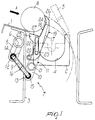
- the reference numeral 1 designates a chute which constitutes a supporting and feeding surface for the bar that must be inserted in the guide 2 of a bar feeder.
- the chute 1 is fixed to a longitudinal beam 3 of the feeder at a higher level than the guide 2.
- the guide 2 is constituted by a U-shaped element which lies longitudinally and forms a guiding channel 4 open upwards and which, during the machining of the bar, is closed by a cover 5, which is shown only schematically in Figure 1.
- a rod 6 is rotatably supported below the chute 1, is parallel to the guide 2, and is connected to a motorization system so as to produce the oscillation of a plurality of elements 7 distributed along the guide 2 to the side thereof.
- the elements 7, only one of which is shown in the figures, are composed of an arm 8 fixed radially to the rod 6 and is articulately connected to the end of a stem 9 which acts as a linkage and is connected, by virtue of its opposite end, to the arm 10 of a lever 11 which is pivoted in a rocker-like manner in the longitudinal beam 3.
- the articulations of the stem 9 in the arms 8 and 10 are constituted by pivots 12 and 13 which are diametrically crossed by the opposite ends of the stem 9 and can rotate in the respective arms about axes which are parallel to the rod 6.
- the stem 9 is coupled to the pivots 12 and 13 by rings 14 and 15 which are mounted at the ends of the stem 9 and against which the pivots are pushed by a spring 16 which is superimposed on the stem portion that lies between the pivots.
- the couplings between the pivots 12 and 13 and the stem 9 are of an elastic type and allow a certain freedom of movement of the lever 11 with respect to the arm 6.
- the lever 11 which owing to its function is termed bar abutment and follower lever, has a second arm 17 whose length is such that it protrudes, in a substantially upright angular position of the lever 11, above the extension of the chute 1.
- the upright position is the one in which the arm 11, with its front edge 18, acts as abutment for a bar B which descends from the chute 1, while the horizontal position is the one in which the bar B is deposited into the channel 4 of the guide 2.
- a second lever is operatively associated with the lever 11 and is adjacent thereto.
- the supporting lever 19 is articulated to the beam 3 about an axis 20 which lies above the articulation axis 21 of the abutment lever 11.
- the lever 19 comprises a slot 22 in which a pin 23 is engaged which protrudes laterally from the arm 17 of the lever 11.
- the slot 22 and the pivot 23 form a slot link which allows the lever 19 to perform angular strokes which are different from those of the lever 11 with which it is associated.
- the lever 19 has a front edge 24 which is co-planar with respect to the front edge 18 of the lever 11.
- the lever 11 has reached a substantially horizontal position, the front edge 24 of the lever 19 has descended below the front edge 18 of the lever 11.
- a central expansion 25 and a tip expansion 26 protrude from the front edge 24 of the lever 19.
- the central expansion 25 has a straight edge 27 which forms a V-shaped slot 28 together with the front edge 24.
- the edge 27 forms, with respect to the edge 24, such an angle that when the lever 19 is in the upright position the edge 27 is parallel to the chute 1.
- the tip expansion 26 is meant to retain the bar, preventing it from leaving the front edge 18 and 24 of the levers 11 and 19.
- the two levers 11 and 19 are arranged in an upright position, so that their front edges 18 and 24 are co-planar.
- the lever 19 By imparting to the elements 7 an oscillation in the direction A by actuating the rod 6, the lever 19, by means of the slot link 22 and 23, surpasses the lever 11, so that the bar B remains in abutment against the front edge 18 of the lever 11 and rests on the edge 27 of the expansion 25 of the lever 19.
- the bar B follows a path which is substantially shaped like an arc and allows it to enter the channel 4 of the guide 2 and be accompanied by the lever 11 until it touches the bottom of said channel.
- the slot link 22 and 23 allows to support the bar along a longer curved path. This is allowed by the fact the once the lever 19 has surpassed the arm 17, the slot 28 is formed by the edges 18 and 27 and, by virtue of the rotation of the lever 19 with respect to the lever 11, moves toward the end of the edge 27.
- the last portion of the transfer path covered by the bar has a substantially steeper inclination which allows more reliable entry into the guiding channel. It is particularly advantageous that the bar continues to be supported by the lever 11 until it is deposited in the channel 4. This, in addition to avoiding stresses which can be critical for the structure of the feeder, produces a considerable reduction in the noise level, which is particularly high in conventional machines since the fall of the bar into the guide is not followed in any way.
- the materials employed may be any according to requirements and to the state of the art.
Landscapes
- Engineering & Computer Science (AREA)
- Mechanical Engineering (AREA)
- Chutes (AREA)
- Intermediate Stations On Conveyors (AREA)
- Attitude Control For Articles On Conveyors (AREA)
- Turning (AREA)
- Feeding Of Articles To Conveyors (AREA)
Applications Claiming Priority (2)
| Application Number | Priority Date | Filing Date | Title |
|---|---|---|---|
| ITBO970548 | 1997-09-09 | ||
| IT97BO000548A IT1294200B1 (it) | 1997-09-09 | 1997-09-09 | Dispositivo per il trasferimento di una barra da un piano di appoggio nel canale di guida di un caricatore di barre. |
Publications (2)
| Publication Number | Publication Date |
|---|---|
| EP0901879A1 true EP0901879A1 (de) | 1999-03-17 |
| EP0901879B1 EP0901879B1 (de) | 2003-05-07 |
Family
ID=11342522
Family Applications (1)
| Application Number | Title | Priority Date | Filing Date |
|---|---|---|---|
| EP98114901A Expired - Lifetime EP0901879B1 (de) | 1997-09-09 | 1998-08-07 | Vorrichtung zum Überführen von Stangen von einer Stützfläche in den Führungskanal einer Stangenzuführvorrichtung |
Country Status (5)
| Country | Link |
|---|---|
| US (1) | US6012893A (de) |
| EP (1) | EP0901879B1 (de) |
| JP (1) | JPH11180520A (de) |
| DE (1) | DE69814270T2 (de) |
| IT (1) | IT1294200B1 (de) |
Cited By (3)
| Publication number | Priority date | Publication date | Assignee | Title |
|---|---|---|---|---|
| EP1224991A1 (de) * | 2001-01-23 | 2002-07-24 | IEMCA Giuliani Macchine Italia S.p.A. | Vorrichtung zum Überführen von Stangen in den Führungskanal einer Stangenzuführvorrichtung |
| CN104014990A (zh) * | 2014-04-22 | 2014-09-03 | 广东工业大学 | 轴双端面精密高效打孔加工装置 |
| KR102722221B1 (ko) * | 2024-04-18 | 2024-10-28 | 김영달 | 가공용 파이프 계단식 이동자동장치 |
Families Citing this family (8)
| Publication number | Priority date | Publication date | Assignee | Title |
|---|---|---|---|---|
| FR2806066B1 (fr) * | 2000-03-09 | 2002-05-03 | Dubuit Mach | Dispositif d'alimentation pour alimenter en objets des porte-objets, en particulier pour machine a imprimer, et machine a imprimer equipee d'un tel dispositif |
| EP1924149B1 (de) * | 2005-05-23 | 2017-08-02 | Intercontinental Great Brands LLC | Süssware mit einer elastomeren komponente, einer gegarten saccharidkomponente und einem geschmacksstoff |
| WO2007098489A2 (en) * | 2006-02-22 | 2007-08-30 | Kneebusch William C | Method and apparatus for feeding bars into a cutting lathe |
| EP2492041B1 (de) * | 2011-02-25 | 2015-01-14 | TRUMPF Werkzeugmaschinen GmbH + Co. KG | Flexible Vorrichtung mit einer Rohrbearbeitungsvorrichtung ; Verfahren zum Entladen eines Rohres unter Verwendung einer solchen Vorrichtung |
| FI125731B (fi) * | 2013-04-24 | 2016-01-29 | Sovellusmestarit Oy | Menetelmä ja laite lieriömäisen kappaleen vastaanottamiseksi sekä käyttö |
| CN106441181A (zh) * | 2016-08-31 | 2017-02-22 | 浙江通泰轴承有限公司 | 一种轴承检测装置中的翻转机构 |
| USD884756S1 (en) * | 2016-12-23 | 2020-05-19 | Bucci Automations S.p.A. | Part of lathe |
| CN109455456B (zh) * | 2018-12-12 | 2024-03-08 | 科德普(厦门)自动化科技有限公司 | 棒材送料机的送料轨道 |
Citations (5)
| Publication number | Priority date | Publication date | Assignee | Title |
|---|---|---|---|---|
| US2573848A (en) * | 1950-06-16 | 1951-11-06 | Nat Tube Co | Pipe transfer apparatus |
| US3118546A (en) * | 1961-11-03 | 1964-01-21 | Taylor Wilson Mfg Co | Apparatus for handling elongated articles |
| US3419159A (en) * | 1966-12-30 | 1968-12-31 | Sundstrand Corp | Bar loading apparatus |
| DE3338281A1 (de) * | 1983-10-21 | 1985-05-02 | Betriebsforschungsinstitut VDEh - Institut für angewandte Forschung GmbH, 4000 Düsseldorf | Vorrichtung zum sammeln und zum vereinzeln von stabfoermigem walzgut |
| DE3424571C1 (de) * | 1984-07-04 | 1986-02-06 | J.H. Schmitz Söhne GmbH, 4100 Duisburg | Vorrichtung zum geräuscharmen Ablegen von Stangenprofilen, insbes. Stäben und Rohren, in eine Sammelmulde |
Family Cites Families (7)
| Publication number | Priority date | Publication date | Assignee | Title |
|---|---|---|---|---|
| US3103939A (en) * | 1962-09-07 | 1963-09-17 | United States Steel Corp | Apparatus for immersing and draining pipe lengths |
| US3306472A (en) * | 1965-04-22 | 1967-02-28 | Americraft Mfg Co | Adjustable gate for bar stock |
| US3446367A (en) * | 1967-05-23 | 1969-05-27 | Pacific Pipeline Construction | Conveyor for pipe sections |
| US3757960A (en) * | 1971-12-22 | 1973-09-11 | Morgan Construction Co | Material handling apparatus |
| US4212584A (en) * | 1978-10-25 | 1980-07-15 | American Can Company | Material handling apparatus |
| SU1017626A1 (ru) * | 1982-01-11 | 1983-05-15 | Государственный Институт По Проектированию Предприятий Машиностроения Для Животноводства И Кормопроизводства | Устройство дл передачи цилиндрических изделий |
| SU1414558A1 (ru) * | 1986-02-14 | 1988-08-07 | Предприятие П/Я В-2330 | Устройство дл поштучной выдачи цилиндрических деталей |
-
1997
- 1997-09-09 IT IT97BO000548A patent/IT1294200B1/it active IP Right Grant
-
1998
- 1998-07-29 US US09/124,748 patent/US6012893A/en not_active Expired - Fee Related
- 1998-08-07 EP EP98114901A patent/EP0901879B1/de not_active Expired - Lifetime
- 1998-08-07 DE DE69814270T patent/DE69814270T2/de not_active Expired - Fee Related
- 1998-09-07 JP JP10252937A patent/JPH11180520A/ja active Pending
Patent Citations (5)
| Publication number | Priority date | Publication date | Assignee | Title |
|---|---|---|---|---|
| US2573848A (en) * | 1950-06-16 | 1951-11-06 | Nat Tube Co | Pipe transfer apparatus |
| US3118546A (en) * | 1961-11-03 | 1964-01-21 | Taylor Wilson Mfg Co | Apparatus for handling elongated articles |
| US3419159A (en) * | 1966-12-30 | 1968-12-31 | Sundstrand Corp | Bar loading apparatus |
| DE3338281A1 (de) * | 1983-10-21 | 1985-05-02 | Betriebsforschungsinstitut VDEh - Institut für angewandte Forschung GmbH, 4000 Düsseldorf | Vorrichtung zum sammeln und zum vereinzeln von stabfoermigem walzgut |
| DE3424571C1 (de) * | 1984-07-04 | 1986-02-06 | J.H. Schmitz Söhne GmbH, 4100 Duisburg | Vorrichtung zum geräuscharmen Ablegen von Stangenprofilen, insbes. Stäben und Rohren, in eine Sammelmulde |
Cited By (3)
| Publication number | Priority date | Publication date | Assignee | Title |
|---|---|---|---|---|
| EP1224991A1 (de) * | 2001-01-23 | 2002-07-24 | IEMCA Giuliani Macchine Italia S.p.A. | Vorrichtung zum Überführen von Stangen in den Führungskanal einer Stangenzuführvorrichtung |
| CN104014990A (zh) * | 2014-04-22 | 2014-09-03 | 广东工业大学 | 轴双端面精密高效打孔加工装置 |
| KR102722221B1 (ko) * | 2024-04-18 | 2024-10-28 | 김영달 | 가공용 파이프 계단식 이동자동장치 |
Also Published As
| Publication number | Publication date |
|---|---|
| IT1294200B1 (it) | 1999-03-22 |
| JPH11180520A (ja) | 1999-07-06 |
| EP0901879B1 (de) | 2003-05-07 |
| DE69814270T2 (de) | 2003-11-13 |
| DE69814270D1 (de) | 2003-06-12 |
| ITBO970548A1 (it) | 1999-03-09 |
| ITBO970548A0 (it) | 1997-09-09 |
| US6012893A (en) | 2000-01-11 |
Similar Documents
| Publication | Publication Date | Title |
|---|---|---|
| EP0901879B1 (de) | Vorrichtung zum Überführen von Stangen von einer Stützfläche in den Führungskanal einer Stangenzuführvorrichtung | |
| JP4218773B2 (ja) | 取り扱い装置、特に挿入器 | |
| US4354588A (en) | Device on an attachment machine | |
| IT9019945A1 (it) | Macchina utensile, in particolare rettificatrice di precisione | |
| GB2279644A (en) | Sheet jogger | |
| US2371126A (en) | Apparatus for feeding-articles from | |
| EP0374747A1 (de) | Zweirichtungs-Fahrvorrichtung zum seitlichen Sortieren von Gegenständen in Transportsystemen mit flexibler Bahn | |
| US4430882A (en) | Multi-stage metal-working machine | |
| CZ281426B6 (cs) | Ovládací zařízení pro vysokorychlostní rotační listové stroje | |
| US2886166A (en) | Conveyors | |
| AU2004218631A1 (en) | Working station of a machine processing plate elements | |
| JP7100393B2 (ja) | 掴線器、および、線材切分工具 | |
| KR100493997B1 (ko) | 중량 경감용 정지 부재를 갖는 얀 공급장치 | |
| US4463873A (en) | Article transfer apparatus | |
| JP2006181846A (ja) | 書類等の綴じ具 | |
| CN101882537A (zh) | 用于断路器的信号装置和包括该信号装置的电气设备 | |
| EP1060665A2 (de) | Stützklammer | |
| JPS59156611A (ja) | 経路切替機構を備えた剪断機 | |
| US20040154221A1 (en) | Feeding station for processing bulbous flowers | |
| EP0943379A2 (de) | Verfahren und Vorrrichtung zum automatischen Biegen von profilierten Metallelementen oder dergleichen | |
| CN1260414C (zh) | 剑杆织机的接纱器 | |
| SE501205C2 (sv) | Anordning vid verktyg | |
| US2207080A (en) | Thread cutter for looms | |
| US2311722A (en) | Machine for grading eggs by weight | |
| EP1270266B1 (de) | Hilfseinschubanordnung für Briefumschlagfüllmaschinen |
Legal Events
| Date | Code | Title | Description |
|---|---|---|---|
| PUAI | Public reference made under article 153(3) epc to a published international application that has entered the european phase |
Free format text: ORIGINAL CODE: 0009012 |
|
| AK | Designated contracting states |
Kind code of ref document: A1 Designated state(s): CH DE FR GB LI |
|
| AX | Request for extension of the european patent |
Free format text: AL;LT;LV;MK;RO;SI |
|
| 17P | Request for examination filed |
Effective date: 19990826 |
|
| AKX | Designation fees paid |
Free format text: CH DE FR GB LI |
|
| 17Q | First examination report despatched |
Effective date: 20010817 |
|
| GRAG | Despatch of communication of intention to grant |
Free format text: ORIGINAL CODE: EPIDOS AGRA |
|
| GRAG | Despatch of communication of intention to grant |
Free format text: ORIGINAL CODE: EPIDOS AGRA |
|
| GRAH | Despatch of communication of intention to grant a patent |
Free format text: ORIGINAL CODE: EPIDOS IGRA |
|
| GRAH | Despatch of communication of intention to grant a patent |
Free format text: ORIGINAL CODE: EPIDOS IGRA |
|
| GRAA | (expected) grant |
Free format text: ORIGINAL CODE: 0009210 |
|
| AK | Designated contracting states |
Designated state(s): CH DE FR GB LI |
|
| REG | Reference to a national code |
Ref country code: GB Ref legal event code: FG4D |
|
| REG | Reference to a national code |
Ref country code: CH Ref legal event code: EP |
|
| REF | Corresponds to: |
Ref document number: 69814270 Country of ref document: DE Date of ref document: 20030612 Kind code of ref document: P |
|
| REG | Reference to a national code |
Ref country code: CH Ref legal event code: NV Representative=s name: PATENTANWALTSBUERO DIPL.-ING. S. V. KULHAVY + CO. |
|
| PG25 | Lapsed in a contracting state [announced via postgrant information from national office to epo] |
Ref country code: GB Free format text: LAPSE BECAUSE OF NON-PAYMENT OF DUE FEES Effective date: 20030807 |
|
| PG25 | Lapsed in a contracting state [announced via postgrant information from national office to epo] |
Ref country code: LI Free format text: LAPSE BECAUSE OF NON-PAYMENT OF DUE FEES Effective date: 20030831 Ref country code: CH Free format text: LAPSE BECAUSE OF NON-PAYMENT OF DUE FEES Effective date: 20030831 |
|
| ET | Fr: translation filed | ||
| PG25 | Lapsed in a contracting state [announced via postgrant information from national office to epo] |
Ref country code: DE Free format text: LAPSE BECAUSE OF NON-PAYMENT OF DUE FEES Effective date: 20040302 |
|
| PLBE | No opposition filed within time limit |
Free format text: ORIGINAL CODE: 0009261 |
|
| STAA | Information on the status of an ep patent application or granted ep patent |
Free format text: STATUS: NO OPPOSITION FILED WITHIN TIME LIMIT |
|
| GBPC | Gb: european patent ceased through non-payment of renewal fee |
Effective date: 20030807 |
|
| REG | Reference to a national code |
Ref country code: CH Ref legal event code: PL |
|
| 26N | No opposition filed |
Effective date: 20040210 |
|
| PG25 | Lapsed in a contracting state [announced via postgrant information from national office to epo] |
Ref country code: FR Free format text: LAPSE BECAUSE OF NON-PAYMENT OF DUE FEES Effective date: 20030831 |
|
| REG | Reference to a national code |
Ref country code: FR Ref legal event code: ST Effective date: 20111125 |