EP0901895A1 - Machine de forage - Google Patents
Machine de forage Download PDFInfo
- Publication number
- EP0901895A1 EP0901895A1 EP98810874A EP98810874A EP0901895A1 EP 0901895 A1 EP0901895 A1 EP 0901895A1 EP 98810874 A EP98810874 A EP 98810874A EP 98810874 A EP98810874 A EP 98810874A EP 0901895 A1 EP0901895 A1 EP 0901895A1
- Authority
- EP
- European Patent Office
- Prior art keywords
- drilling
- longitudinal axis
- housing part
- drilling tool
- bearing
- Prior art date
- Legal status (The legal status is an assumption and is not a legal conclusion. Google has not performed a legal analysis and makes no representation as to the accuracy of the status listed.)
- Granted
Links
Images


Classifications
-
- B—PERFORMING OPERATIONS; TRANSPORTING
- B23—MACHINE TOOLS; METAL-WORKING NOT OTHERWISE PROVIDED FOR
- B23Q—DETAILS, COMPONENTS, OR ACCESSORIES FOR MACHINE TOOLS, e.g. ARRANGEMENTS FOR COPYING OR CONTROLLING; MACHINE TOOLS IN GENERAL CHARACTERISED BY THE CONSTRUCTION OF PARTICULAR DETAILS OR COMPONENTS; COMBINATIONS OR ASSOCIATIONS OF METAL-WORKING MACHINES, NOT DIRECTED TO A PARTICULAR RESULT
- B23Q1/00—Members which are comprised in the general build-up of a form of machine, particularly relatively large fixed members
- B23Q1/25—Movable or adjustable work or tool supports
- B23Q1/44—Movable or adjustable work or tool supports using particular mechanisms
- B23Q1/50—Movable or adjustable work or tool supports using particular mechanisms with rotating pairs only, the rotating pairs being the first two elements of the mechanism
- B23Q1/54—Movable or adjustable work or tool supports using particular mechanisms with rotating pairs only, the rotating pairs being the first two elements of the mechanism two rotating pairs only
-
- B—PERFORMING OPERATIONS; TRANSPORTING
- B28—WORKING CEMENT, CLAY, OR STONE
- B28D—WORKING STONE OR STONE-LIKE MATERIALS
- B28D1/00—Working stone or stone-like materials, e.g. brick, concrete or glass, not provided for elsewhere; Machines, devices, tools therefor
- B28D1/02—Working stone or stone-like materials, e.g. brick, concrete or glass, not provided for elsewhere; Machines, devices, tools therefor by sawing
- B28D1/04—Working stone or stone-like materials, e.g. brick, concrete or glass, not provided for elsewhere; Machines, devices, tools therefor by sawing with circular or cylindrical saw-blades or saw-discs
- B28D1/041—Working stone or stone-like materials, e.g. brick, concrete or glass, not provided for elsewhere; Machines, devices, tools therefor by sawing with circular or cylindrical saw-blades or saw-discs with cylinder saws, e.g. trepanning; saw cylinders, e.g. having their cutting rim equipped with abrasive particles
-
- B—PERFORMING OPERATIONS; TRANSPORTING
- B23—MACHINE TOOLS; METAL-WORKING NOT OTHERWISE PROVIDED FOR
- B23B—TURNING; BORING
- B23B45/00—Hand-held or like portable drilling machines, e.g. drill guns; Equipment therefor
-
- B—PERFORMING OPERATIONS; TRANSPORTING
- B23—MACHINE TOOLS; METAL-WORKING NOT OTHERWISE PROVIDED FOR
- B23Q—DETAILS, COMPONENTS, OR ACCESSORIES FOR MACHINE TOOLS, e.g. ARRANGEMENTS FOR COPYING OR CONTROLLING; MACHINE TOOLS IN GENERAL CHARACTERISED BY THE CONSTRUCTION OF PARTICULAR DETAILS OR COMPONENTS; COMBINATIONS OR ASSOCIATIONS OF METAL-WORKING MACHINES, NOT DIRECTED TO A PARTICULAR RESULT
- B23Q5/00—Driving or feeding mechanisms; Control arrangements therefor
- B23Q5/02—Driving main working members
- B23Q5/04—Driving main working members rotary shafts, e.g. working-spindles
-
- Y—GENERAL TAGGING OF NEW TECHNOLOGICAL DEVELOPMENTS; GENERAL TAGGING OF CROSS-SECTIONAL TECHNOLOGIES SPANNING OVER SEVERAL SECTIONS OF THE IPC; TECHNICAL SUBJECTS COVERED BY FORMER USPC CROSS-REFERENCE ART COLLECTIONS [XRACs] AND DIGESTS
- Y10—TECHNICAL SUBJECTS COVERED BY FORMER USPC
- Y10T—TECHNICAL SUBJECTS COVERED BY FORMER US CLASSIFICATION
- Y10T408/00—Cutting by use of rotating axially moving tool
- Y10T408/23—Cutting by use of rotating axially moving tool including means to cause Tool to progressively vibrate toward work
-
- Y—GENERAL TAGGING OF NEW TECHNOLOGICAL DEVELOPMENTS; GENERAL TAGGING OF CROSS-SECTIONAL TECHNOLOGIES SPANNING OVER SEVERAL SECTIONS OF THE IPC; TECHNICAL SUBJECTS COVERED BY FORMER USPC CROSS-REFERENCE ART COLLECTIONS [XRACs] AND DIGESTS
- Y10—TECHNICAL SUBJECTS COVERED BY FORMER USPC
- Y10T—TECHNICAL SUBJECTS COVERED BY FORMER US CLASSIFICATION
- Y10T408/00—Cutting by use of rotating axially moving tool
- Y10T408/65—Means to drive tool
-
- Y—GENERAL TAGGING OF NEW TECHNOLOGICAL DEVELOPMENTS; GENERAL TAGGING OF CROSS-SECTIONAL TECHNOLOGIES SPANNING OVER SEVERAL SECTIONS OF THE IPC; TECHNICAL SUBJECTS COVERED BY FORMER USPC CROSS-REFERENCE ART COLLECTIONS [XRACs] AND DIGESTS
- Y10—TECHNICAL SUBJECTS COVERED BY FORMER USPC
- Y10T—TECHNICAL SUBJECTS COVERED BY FORMER US CLASSIFICATION
- Y10T408/00—Cutting by use of rotating axially moving tool
- Y10T408/83—Tool-support with means to move Tool relative to tool-support
- Y10T408/85—Tool-support with means to move Tool relative to tool-support to move radially
- Y10T408/858—Moving means including wedge, screw or cam
- Y10T408/8595—Pivotable tool-support
-
- Y—GENERAL TAGGING OF NEW TECHNOLOGICAL DEVELOPMENTS; GENERAL TAGGING OF CROSS-SECTIONAL TECHNOLOGIES SPANNING OVER SEVERAL SECTIONS OF THE IPC; TECHNICAL SUBJECTS COVERED BY FORMER USPC CROSS-REFERENCE ART COLLECTIONS [XRACs] AND DIGESTS
- Y10—TECHNICAL SUBJECTS COVERED BY FORMER USPC
- Y10T—TECHNICAL SUBJECTS COVERED BY FORMER US CLASSIFICATION
- Y10T408/00—Cutting by use of rotating axially moving tool
- Y10T408/86—Tool-support with means to permit positioning of the Tool relative to support
- Y10T408/865—Pivotable Tool
Definitions
- the invention relates to a drilling device according to the preamble of patent claim 1.
- drilling tools with drilling tools with a diamond-tipped cutting area used.
- a drill is known for example from DE-PS 34 34 261 and has in addition to an electrical Drive unit a gear and a receptacle for the drilling tool.
- the Recording has a central recording area for the insertion end of the Drilling tool and is in a housing part over two at a distance from each other spaced bearings rotatably mounted.
- This well-known device stands out characterized in that the longitudinal axis of the receptacle and the longitudinal axis of the Drilling tool with respect to a longitudinal axis of a housing part of the drilling device are coaxially aligned and rotatably mounted.
- Drilling Especially with hand-held Drilling is drilling because of the high contact pressure required and the relative long drilling times exhausting.
- the contact pressure is applied to the entire face of the distributed cutting direction side cutting area of the drilling tool, so that only a low surface pressure results and the above diamonds only little in the Penetrate underground and can dismantle it. Due to the low immersion in the surface tends to round the diamond tips and the whole The drilling process is developing increasingly poorly. The drilling speed is slow.
- the invention has for its object to provide a drill with which low pressing force can achieve a high drilling speed.
- This task is solved by a drilling rig, which is characteristic of the Section of claim 1 features listed.
- a drilling rig which is characteristic of the Section of claim 1 features listed.
- This solution according to the invention becomes the rotating drilling tool tilting or tumbling movement on at least one of the two free End areas of the drilling tool overlaid.
- the longitudinal axis of the drilling tool is thereby periodically inclined to the longitudinal axis of the housing part. Because of the inclination in each case part of the end face of the drilling tool on the drilling direction
- the surface is lifted off, so that only part of the cutting area is used worked the underground.
- the contact pressure therefore only affects a small one Cutting surface so that there is a very high surface pressure.
- the receptacle can be sleeve-shaped, for example, with the drilling tool in an inner receiving area of the receptacle by means of an insertion end is axially fixable.
- the insertion end is, for example, from at least one bearing element surrounded by the insertion end on the side of the receiving area supports.
- About an inclination of the longitudinal axis of the drilling tool with respect to the longitudinal axis to be able to achieve the housing part is preferably at least one bearing element can be arranged inclined with respect to the longitudinal axis of the housing part.
- the bearing element can for this purpose, for example, a receiving opening for the Have insertion end of the drilling tool, the longitudinal axis inclined to the longitudinal axis of the housing part runs.
- the insertion end is supported laterally via two axially one behind the other arranged bearings, for example, the receiving openings of both Bearings aligned coaxially with each other, but with respect to the longitudinal axis of the Housing part arranged inclined.
- the lateral support of the insertion end can but also for example by means of at least one elastically designed bearing element take place, loads occurring when working on a substrate the drilling tool act to deform the elastic bearing element and thus to an inclination of the longitudinal axis of the drilling tool relative to the Guide the longitudinal axis of the housing part.
- a free tipping or Tumbling movement of the drilling tool is stimulated, in each case a part of the in End direction of the cutting edge of the drilling tool pointing from the drilling direction Processing point on the surface. Tilting when working on a surface or tumbles the drilling tool, for example, or is during the Processing can be switched on or off.
- the strength of the tipping or The wobble depends on the load on the drilling tool for example, depending on the contact pressure and the performance of one Drill unit drive unit.
- a tilting or tumbling movement of the drilling tool can, for example can be achieved by expediently including the longitudinal axis of the drilling tool the longitudinal axis of the receiving area with respect to the longitudinal axis of the housing part can be arranged inclined.
- the insertion end of the drilling tool is non-rotatable in the Arranged area of the receptacle and the longitudinal axis of the drilling tool runs coaxially to the longitudinal axis of the receiving area.
- the longitudinal axis of the receiving area is at least one in the bearing point displaceable substantially perpendicular to the longitudinal axis of the housing part can be arranged inclined. If, for example, a first bearing point on the longitudinal axis of the Arranged housing part and a second drilling direction bearing point essentially is offset perpendicular to the longitudinal axis of the housing part, then the tilting or wobble-like movement at the free end of the drilling tool on the drilling direction the biggest.
- the second bearing direction on the drilling direction Arranged longitudinal axis of the housing part and the first bearing point essentially is offset perpendicular to the longitudinal axis of the housing part forms the drilling direction second bearing a pivot around which the drilling tool performs a tilting or wobbling movement.
- both bearings are displaceable essentially perpendicular to the longitudinal axis of the housing part, the first bearing is displaced more than the direction of the drilling direction second bearing point, then there is a tilting or a wobbling movement of the Drilling tool possible around an imaginary pivot point, that of the drilling direction free end of the drilling tool is formed. That means the drilling tool at the free end on the drilling direction and none at the opposite free end largest lateral or wobbling movement.
- the elastic intermediate element is, for example between one of the bearing points and the receptacle or between one of the bearing points and the housing part arranged. So that the longitudinal axis of the recording compared to the Longitudinal axis of the housing part substantially perpendicular to the longitudinal axis of the Housing part can be arranged inclined, for example, the drilling direction side second bearing with the intermediate element and the first bearing with one Swivel bearing in connection.
- This pivot bearing is made of two, for example interlocking, mutually pivotable rings formed. Of course it is possible, the swivel bearing with the first bearing and the drilling direction to bring the second bearing to the intermediate element.
- At least one axle offset element is preferably provided for moving the bearing point, arranged between at least one bearing point and the housing part is.
- This axis offset element is composed, for example, of two interlocking, eccentric rings together which, when rotated together, cause a lateral displacement cause the deposit with which they are connected.
- the axis offset element is, for example, between one of the bearing points and the receptacle or arranged between one of the bearing points and the housing part.
- substantially perpendicular to the longitudinal axis of the housing part can, for example, is the second bearing point on the drilling direction with the axis offset element and the first bearing point in connection with a pivot bearing.
- This Swivel bearing is for example made of two interlocking, mutually pivotable Wrestling formed. It is of course also possible to use the swivel bearing with the first one Bearing point and the drilling bearing side second bearing point with the intermediate element in To connect.
- the arrangement of an axis offset element is, for example also possible at both bearings.
- the speed is preferably the Intermediate sleeve and the speed of the recording out of sync.
- the intermediate sleeve can for example, rotate slower than the shot.
- a rotary movement is transmitted from the holder to the drilling tool advantageously by means of a receptacle part that can be inserted into the receptacle an end of the carrier body facing away from the cutting area is connected and extends radially beyond the carrier body.
- the receiving part can for example be made of an elastic Material.
- the elastic material can be rubber that is on the outside of the the end of the carrier body facing away from the cutting area is vulcanized.
- the elastic material can be plastic or magnesium.
- the drilling tool has, for example, a tubular support body
- the carrier body is to this Purpose on the outside in the area of the insertion end with depressions or Provide through openings into which the material of the receiving part can penetrate, if this material is vulcanized or sprayed onto the insertion end is applied.
- the invention includes other elastic or non-elastic Materials and other joining techniques with which the receiving part with the Cannot connect plugged in.
- the drilling device according to the invention can be either a hand-held or a stand-guided one Act drill.
- the processing of a substrate with the inventive The drill can be carried out either wet or dry.
- improved drilling results can also be made diamond-tipped carbide or steel tools, such as HSS drills to lead.
- the tilting or overlapping of the rotary movement of the drilling tool wobbling movement also has a beneficial effect on the cutting machining of the Using cutting tools or wall saws as well as surface processing a base by means of, for example, an axially tumbling cup wheel out.
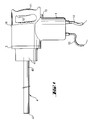
- FIG. 1 shows a drilling device according to the invention, which has a device housing 1, a drive unit, not shown, in the device housing 1, a handle 11, a in the handle 11 integrated operating switch 12, a coolant line 14, a electrical connecting line 13, a housing part 3 and a housing part 3 outstanding drilling tool 4.
- the drilling tool 4 has a first Free end portion of a tubular support body 46 and an insertion end 41 an annular cutting body 47 on a second free end region.
- the attachment of the handle 11 to the device housing 1 is used Hinge 15 and a hinge 15 substantially diametrically opposite arranged closure 16.
- the handle 11 is at least out of the hinge 15 the axial projection surface of the drilling tool 4 is pivotable.
- the housing part 3 is essentially tubular formed and has an inner wall 32 on which two of each other support spaced bearings 33, 34 in the form of two ball bearings.
- the inner rings these ball bearings are formed with a substantially sleeve-shaped Recording 35 in connection.
- a central receiving area 36 is designed in a stepped manner and tapers in the direction of drilling. At an end area pointing counter to the drilling direction the receiving area has a circumferential inner profile 37 in Form of an internal toothing.
- a rotary handle element 31 is located in between the two bearing points 33, 34 Shape of a gear that is rotatably connected to the receptacle 35.
- the Rotary handle element 31 is with its outer profile in a not shown positive connection with the drive unit, also not shown in Fig. 1 and serves to transmit a rotary movement originating from the drive unit on the receptacle 35 or on the drilling tool 4 inserted in the receptacle 35.
- the receiving region 36 of the receptacle 35 serves to receive the insertion end 41.
- the outer diameter of the tubular support body is smaller than the smallest Diameter of the receiving area 36 of the receiving device 35.
- a cover 2 which adjoins the housing part 3 against the drilling direction, has an inner receiving area 21 which is stepped in the drilling direction expanded.
- the end region of the cover facing away from the drilling direction has one Central passage opening 24, which serves the supply of coolant and with the in Fig. 1 shown coolant line 14 is connected. The connection of the passage opening 24 with the coolant line 14 is not shown.
- the cover 2 experiences axial support against the drilling direction, for example from the handle 11, which in a closed position against at least one of the presses against the drilling direction facing surfaces of the lid 2.
- the interaction 1 with the lid 2 is not shown.
- the Lid 2 can be part of the handle 11, for example, so that the lid 2 of the housing part 3 can be lifted when the handle 11 pivots into an open position is and thereby releases an axial projection surface of the drilling tool 4, so that, for example, the removal of a drill core from the drilling tool 4 or a removal of the drilling tool 4 from the receptacle 35 against the drilling direction can be done.
- the receptacle 35 has between the inner profile 37 and the free end facing away from the direction of drilling a first cylindrical Section on.
- Another, second cylindrical section is part of the Receiving area formed, which has a smaller inner diameter than that Section in which the first, cylindrical section is located.
- a first guide element 43 has an outer diameter on which is essentially the inside diameter of the first cylindrical Section corresponds.
- the second guide element 42 has an outer diameter on the substantially the inner diameter of the second cylindrical portion corresponds.
- the tubular one is between the two disk-shaped guide elements 42, 43 Carrier body 46 surrounded by an elastic bearing element 45.
- Part of this Bearing element 45 has an inner profile 37 of the receiving area 35 coordinated outer profile 48. In the direction of drilling, this immediately follows second disk-shaped guide element 42 a further elastic bearing element 44 on.
- the outer diameter of this further bearing element 44 corresponds essentially the outer diameter of the guide element 42.
- a bearing 22 in the form of a ball bearing arranged, the rotatable mounting and the axial guidance of a support element 23 serves.
- the support element 23 penetrates one with a shaft region Inner ring of the bearing 22.
- the end region of the support element 23 on the drilling direction side has a flange-like extension 26.
- a spring element 25 which consists of several Composed of disc springs.
- the entire support element 23 has a central one Through hole through which coolant can reach the drilling tool.
- Sealing element may be arranged so that coolant which passes through the passage opening 24 penetrates into the inner receiving area 21, does not reach the bearing 22 can.
- Tuning the elastic Bearing elements 44, 45 is such that the drilling tool 4 is opposite the receptacle 35 can be inclined at an angle of 0.10 ° to 0.8 °.
- the receptacle 35 has three arranged one behind the other Areas whose diameters widen step-wise against the drilling direction. Two of the areas are cylindrical. The area with the largest The diameter is at an end region of the hole facing away from the drilling direction Recording 35 and is provided with a tooth-shaped inner profile 37.
- the insertion end 41 of the drilling tool 4 is surrounded by a receiving part 6 which has three sections.
- a first section on the drilling direction side is cylindrical educated.
- the outside diameter of this first section corresponds to essentially the inner diameter of the smallest area of the receptacle 35 second section, opposite to the first section, is more eccentric Outer cone 28 is formed, which tapers against the drilling direction.
- a third Section extending between the first and second sections radially over the other two sections and has a tooth-shaped outer profile 48, which form-fit with the inner profile 37 of the receptacle 35 cooperates.
- a bearing 22 in the form of a ball bearing arranged, the receiving and the rotatable mounting of a support element 23 serves.
- the support member 23 has a through hole and an eccentric Inner cone 29, which widens in the direction of drilling.
- the transition area at the insertion end from the third to the second section is stepped.
- the stage forms an annular stop surface pointing against the drilling direction, on which supports a spring element 25 in the form of a compression spring and against one in the drilling direction facing end face of the support member 23 presses.
- coolant reaches the drilling tool 4.
- a sealing element On the opposite of the drilling direction lying side of the bearing 22 can be a sealing element, not shown be arranged so that coolant, which passes through the passage opening 24 in the inner Receiving area 21 penetrates, can not get to the bearing 22.
- a two-part pivot bearing 39 Between the ball bearing forming the bearing 33 and the receptacle 35 is a two-part pivot bearing 39 arranged, the excessive loads on the ball bearing prevented when the receptacle 35 tilts relative to the housing part 3.
- a arranged annular, elastic intermediate element 38 Between the ball bearing forming the bearing 34 and the receptacle 35 is a arranged annular, elastic intermediate element 38, which occurs when it occurs large radial forces deformed such that the receptacle 35 and that in the receptacle 35 used drilling tool 4 tends towards the housing part 3.
- the drilling tool 4 can be inclined relative to the receptacle 35 at an angle of 0.10 ° to 0.8 °.
- Sealing element can prevent coolant from reaching bearing 34 can reach.
- the receptacle 35 remains in relation to the housing part 3 in the illustrated axial position.
- the elastic intermediate element 38 is not deformed and the Recording 35 or the drilling tool 4 run coaxially to the longitudinal axis of the housing part 3rd
- the contact pressure can be increased. This leads to a axial displacement of the drilling tool 4 relative to the receptacle 35 against the Drilling direction.
- the spring element 25 is compressed and the eccentric Outer cone 28 of the receiving part 6 surrounding the insertion end 41 arrives with the eccentric inner cone 29 of the support element 23 in operative connection. Due to the eccentric design of the two cones results in a radial force leading to a Deformation of the elastic intermediate element 38 and an inclination of the receptacle 35 or the drilling tool 4 leads to the housing part 3.
- the high of Deformation of the elastic intermediate element 38 and the resultant The inclination of the receptacle 35 depends on the contact pressure. The greater the contact pressure the greater the inclination of the drilling tool 4 relative to the housing part 3.
- a housing part 3 which has a flange-like at a free end Extension, which by means of connecting elements, not shown, with the Device housing 1 is connected.
- the housing part 3 is essentially tubular and has an inner wall 32 on which two spaced apart Support bearings 40a, 40b in the form of two ball bearings.
- the inner rings of this Bearings 40a, 40b are connected to an intermediate sleeve 5, the inner wall of which 51 runs eccentrically to the outer wall. Support themselves on the inner wall 51 two spaced apart bearings 33, 34 in the form of two ball bearings.
- the Inner rings of these ball bearings are of essentially sleeve-shaped design Recording 35 in connection.
- an axis offset element 53 which is composed of two eccentrically shaped rings. By mutually rotating these rings, the inclination of the receptacle 35 with respect to the longitudinal axis of the intermediate sleeve 5 or with respect to the longitudinal axis of the Housing part 3 influences.
- the inclination can be 0.10 ° to 0.8 °.
- the receptacle 35 has a cylindrical receptacle area 36 which is located at an end region lying opposite the drilling direction gradually expanded.
- the transition area of this extension is tooth-shaped Provided inner profile 37.
- the insertion end 41 of the drilling tool 4 is surrounded by a receiving part 6 which has three sections.
- a first section on the drilling direction side is cylindrical educated. The outside diameter of this first section corresponds to essentially the inner diameter of the cylindrical receiving area.
- a second Section, which lies opposite the first section, is flanged and points out an annular stop surface pointing in the direction of drilling. Between the first and The second section is the third section, which is a form-fitting with the Internal profile 37 of the receptacle 35 cooperating, tooth-shaped Has outer profile 48.
- the intermediate sleeve 5 projects beyond the housing part 3 on the drilling direction side outer wall of the intermediate sleeve 5 related second rotation Attack element 52 in the form of a gearwheel is in that area of the intermediate sleeve 5 arranged, which projects beyond the housing part 3 on the drilling direction.
- the receptacle 35 projects beyond both the housing part 3 and the drilling direction Intermediate sleeve 5.
- a rotatably connected to the outer wall of the intermediate sleeve 5 standing first rotary handle element 31 in the form of a gear is in that Arranged area of the receptacle 35 which projects beyond the intermediate sleeve 5 on the drilling direction side.
- the first and the second rotary handle element 31, 52 stand with their outer profile in a positive connection, not shown, with that also in FIG. 1, not shown drive unit and serve to transmit at least one of the Drive unit outgoing rotary movement on the intermediate sleeve.
- the speed the rotational movement of the second rotary handle element 52 is at most the same as the speed of the first rotary handle element 31.
- a cover 2 that opposes each other the drilling direction to the housing part 3, has an inner receiving area 21, which widens step-wise in the direction of drilling.
- the direction of drilling End region of the cover facing away has a central passage opening 24 which serves to supply coolant and with the coolant line 14 shown in FIG. 1 communicates.
- the connection of the passage opening 24 to the coolant line 14 is not shown.
- the cover 2 experiences the axial support against the drilling direction, for example, from The handle 11 shown in Fig. 1 against in a closed position presses at least one of the surfaces of the cover 2 pointing counter to the drilling direction.
- the interaction of the handle 11 according to FIG. 1 with the cover 2 is not shown.
- the lid 2 can be part of the handle 11, for example, so that the lid 2 can be lifted off the housing part 3 when the handle 11 is in a is pivoted open position and thereby an axial projection surface of the drilling tool releases, so that for example the removal of a drill core from the Drilling tool or a removal of the drilling tool 4 from the receptacle the drilling direction can take place.
- a bearing 22 in the form of a ball bearing arranged, the rotatable mounting and the axial guidance of a support element 23 serves.
- the support element 23 penetrates one with a shaft region Inner ring of the bearing 22.
- the end region of the support element 23 on the drilling direction side has a flange-like extension 26, which rests on the housing part 3.
- a spring element 25 which is made up of several disc springs.
- the entire support element 23 has a central through-hole through which coolant to the drilling tool 4th can reach.
- a bearing Sealing part On the opposite side of the bearing 22 is a bearing Sealing part arranged so that coolant, which passes through the passage opening 24 in penetrates the inner receiving area 21, can not get to the bearing 22.
- a bearing Sealing part At the There is a bore-side end face of the flange-like extension 26 all-round recess into which a sealing element 27 in the form of an O-ring partially protrudes. This sealing element prevents coolant, which through the central through bore of the support member 23 to Drilling tool arrives, can not penetrate to bearing point 34.
Landscapes
- Engineering & Computer Science (AREA)
- Mechanical Engineering (AREA)
- Mining & Mineral Resources (AREA)
- Processing Of Stones Or Stones Resemblance Materials (AREA)
- Drilling And Boring (AREA)
- Cutting Tools, Boring Holders, And Turrets (AREA)
- Drilling Tools (AREA)
Applications Claiming Priority (2)
| Application Number | Priority Date | Filing Date | Title |
|---|---|---|---|
| DE19740462 | 1997-09-15 | ||
| DE19740462A DE19740462A1 (de) | 1997-09-15 | 1997-09-15 | Bohrgerät |
Publications (2)
| Publication Number | Publication Date |
|---|---|
| EP0901895A1 true EP0901895A1 (fr) | 1999-03-17 |
| EP0901895B1 EP0901895B1 (fr) | 2003-11-12 |
Family
ID=7842359
Family Applications (1)
| Application Number | Title | Priority Date | Filing Date |
|---|---|---|---|
| EP98810874A Expired - Lifetime EP0901895B1 (fr) | 1997-09-15 | 1998-09-02 | Machine de forage |
Country Status (7)
| Country | Link |
|---|---|
| US (1) | US6092965A (fr) |
| EP (1) | EP0901895B1 (fr) |
| JP (1) | JP4331288B2 (fr) |
| KR (1) | KR100567181B1 (fr) |
| AT (1) | ATE254019T1 (fr) |
| DE (2) | DE19740462A1 (fr) |
| ES (1) | ES2210704T3 (fr) |
Cited By (2)
| Publication number | Priority date | Publication date | Assignee | Title |
|---|---|---|---|---|
| US20140241821A1 (en) * | 2012-11-05 | 2014-08-28 | M4 Sciences Llc | Rotating tool holder assembly for modulation assisted machining |
| US10875138B1 (en) | 2016-08-09 | 2020-12-29 | M4 Sciences Llc | Tool holder assembly for machining system |
Families Citing this family (5)
| Publication number | Priority date | Publication date | Assignee | Title |
|---|---|---|---|---|
| FR2969945B1 (fr) * | 2010-12-30 | 2013-07-19 | Sylvain Guerin | Dispositif portatif d'usinage, plus particulierement de percage |
| CA2874272C (fr) | 2012-05-30 | 2021-01-05 | Tellus Oilfield, Inc. | Systeme de forage, mecanisme de rappel et procede permettant un forage directionnel d'un trou de forage |
| CN108436148B (zh) * | 2016-11-04 | 2019-09-24 | 泰州市晨虹数控设备制造有限公司 | 一种打孔机构 |
| WO2019027954A1 (fr) | 2017-07-31 | 2019-02-07 | Milwaukee Electric Tool Corporation | Outil électrique rotatif |
| KR102357464B1 (ko) * | 2020-09-08 | 2022-02-07 | 주식회사 대동에스앤티 | 집진부를 포함한 고정볼트 삽입구 타공장치 |
Citations (1)
| Publication number | Priority date | Publication date | Assignee | Title |
|---|---|---|---|---|
| US5316419A (en) * | 1992-05-05 | 1994-05-31 | Fischerwerke Artur Fischer Gmbh & Co. Kg. | Device for making a drilled hole with an undercut |
Family Cites Families (8)
| Publication number | Priority date | Publication date | Assignee | Title |
|---|---|---|---|---|
| DE3206387A1 (de) * | 1982-02-22 | 1983-09-01 | Hilti AG, 9494 Schaan | Bohrwerkzeug fuer hinterschnittene bohrungen |
| DE3327409A1 (de) * | 1983-07-29 | 1985-02-07 | Hawera Probst Gmbh + Co, 7980 Ravensburg | Bohrwerkzeug zur herstellung von hinterschneidungen in vorgefertigten bohrungen |
| JPH0794125B2 (ja) * | 1991-09-06 | 1995-10-11 | 旭栄研磨加工株式会社 | 硬脆材料の孔あけ加工法及びその加工装置 |
| US5363835A (en) * | 1992-08-31 | 1994-11-15 | Rocktec Limited | Nose block assembly |
| DE4330058A1 (de) * | 1993-09-06 | 1995-03-09 | Fischer Artur Werke Gmbh | Bohrvorrichtung zur Herstellung von Bohrlöchern mit Hinterschneidung |
| US5407018A (en) * | 1994-01-10 | 1995-04-18 | Tc Services | Pneumatic impact tool having improved vibration and noise attenuation |
| DE4418103A1 (de) * | 1994-05-24 | 1995-11-30 | Hilti Ag | Bohr- und/oder Meisselgerät |
| DE19514379A1 (de) * | 1995-04-19 | 1996-10-24 | Fischer Artur Werke Gmbh | Bohrvorrichtung zur Herstellung von Bohrlöchern mit Hinterschneidung |
-
1997
- 1997-09-15 DE DE19740462A patent/DE19740462A1/de not_active Withdrawn
-
1998
- 1998-09-02 DE DE59810144T patent/DE59810144D1/de not_active Expired - Lifetime
- 1998-09-02 AT AT98810874T patent/ATE254019T1/de active
- 1998-09-02 EP EP98810874A patent/EP0901895B1/fr not_active Expired - Lifetime
- 1998-09-02 ES ES98810874T patent/ES2210704T3/es not_active Expired - Lifetime
- 1998-09-10 KR KR1019980037401A patent/KR100567181B1/ko not_active Expired - Lifetime
- 1998-09-14 US US09/152,859 patent/US6092965A/en not_active Expired - Lifetime
- 1998-09-16 JP JP26179898A patent/JP4331288B2/ja not_active Expired - Lifetime
Patent Citations (1)
| Publication number | Priority date | Publication date | Assignee | Title |
|---|---|---|---|---|
| US5316419A (en) * | 1992-05-05 | 1994-05-31 | Fischerwerke Artur Fischer Gmbh & Co. Kg. | Device for making a drilled hole with an undercut |
Cited By (3)
| Publication number | Priority date | Publication date | Assignee | Title |
|---|---|---|---|---|
| US20140241821A1 (en) * | 2012-11-05 | 2014-08-28 | M4 Sciences Llc | Rotating tool holder assembly for modulation assisted machining |
| US10245652B2 (en) * | 2012-11-05 | 2019-04-02 | M4 Sciences Llc | Rotating tool holder assembly for modulation assisted machining |
| US10875138B1 (en) | 2016-08-09 | 2020-12-29 | M4 Sciences Llc | Tool holder assembly for machining system |
Also Published As
| Publication number | Publication date |
|---|---|
| US6092965A (en) | 2000-07-25 |
| KR100567181B1 (ko) | 2006-06-21 |
| JP4331288B2 (ja) | 2009-09-16 |
| JPH11156847A (ja) | 1999-06-15 |
| DE19740462A1 (de) | 1999-03-18 |
| ATE254019T1 (de) | 2003-11-15 |
| KR19990029696A (ko) | 1999-04-26 |
| ES2210704T3 (es) | 2004-07-01 |
| EP0901895B1 (fr) | 2003-11-12 |
| DE59810144D1 (de) | 2003-12-18 |
Similar Documents
| Publication | Publication Date | Title |
|---|---|---|
| EP0385059B1 (fr) | Fôret | |
| EP0783933B1 (fr) | Outil pour forer et ciseler | |
| EP0044386B1 (fr) | Dispositif de perçage en vue de percer un trou présentant une partie détalonnée | |
| DE3819833A1 (de) | Duebelbohrer | |
| DE3310807A1 (de) | Rotierender erdbohrmeissel und verfahren zu seiner herstellung | |
| DE3507817A1 (de) | Bohrer zur erzeugung einer hinterschneidung in einer bohrung | |
| WO2005097384A2 (fr) | Dispositif de serrage extensible | |
| EP0336182B1 (fr) | Dispositif de perçage pour l'usinage de chambrages dans des trous cylindriques | |
| DE102007060469B4 (de) | Führungsvorrichtung eines Bohrers | |
| EP0698436A1 (fr) | Dispositif de forage à fabriquer des trous avec chambrage | |
| EP0901895B1 (fr) | Machine de forage | |
| DE19720635A1 (de) | Schaftmeißel | |
| EP0508103A1 (fr) | Dispositif de forage pour l'usinage des trous à chambrage | |
| DE8221158U1 (de) | Bohrwerkzeug zum erzeugen von bohrloechern mit wenigstens einer erweiterung am bohrlochgrund | |
| EP0408860B1 (fr) | Dispositif pour fabriquer un chambrage dans un trou foré | |
| DE19708176A1 (de) | Werkzeughalter für eine Bohr- und/oder Schlagwerkzeugmaschine | |
| EP0791423B1 (fr) | Dispositif porte-foret avec un foret | |
| DE2653082A1 (de) | Werkzeughalter | |
| DE3029560A1 (de) | Werkzeughalterung an einem schlag- oder drehschlaghammer | |
| EP0891832A1 (fr) | Foret | |
| DE10041911B4 (de) | Diamantbohrkrone | |
| DE3515661A1 (de) | Elektropneumatischer drehschlagbohrhammer | |
| CH655272A5 (de) | Bohrhammer mit werkzeughalter. | |
| DE3613526C2 (fr) | ||
| DE2752544C2 (de) | Schlagbohrspitze |
Legal Events
| Date | Code | Title | Description |
|---|---|---|---|
| PUAI | Public reference made under article 153(3) epc to a published international application that has entered the european phase |
Free format text: ORIGINAL CODE: 0009012 |
|
| AK | Designated contracting states |
Kind code of ref document: A1 Designated state(s): AT BE CH DE ES FR GB IT LI NL SE |
|
| AX | Request for extension of the european patent |
Free format text: AL;LT;LV;MK;RO;SI |
|
| 17P | Request for examination filed |
Effective date: 19990917 |
|
| AKX | Designation fees paid |
Free format text: AT BE CH DE ES FR GB IT LI NL SE |
|
| 17Q | First examination report despatched |
Effective date: 20021119 |
|
| GRAH | Despatch of communication of intention to grant a patent |
Free format text: ORIGINAL CODE: EPIDOS IGRA |
|
| GRAS | Grant fee paid |
Free format text: ORIGINAL CODE: EPIDOSNIGR3 |
|
| GRAA | (expected) grant |
Free format text: ORIGINAL CODE: 0009210 |
|
| AK | Designated contracting states |
Kind code of ref document: B1 Designated state(s): AT BE CH DE ES FR GB IT LI NL SE |
|
| REG | Reference to a national code |
Ref country code: GB Ref legal event code: FG4D Free format text: NOT ENGLISH |
|
| REG | Reference to a national code |
Ref country code: CH Ref legal event code: EP |
|
| REF | Corresponds to: |
Ref document number: 59810144 Country of ref document: DE Date of ref document: 20031218 Kind code of ref document: P |
|
| REG | Reference to a national code |
Ref country code: SE Ref legal event code: TRGR |
|
| GBT | Gb: translation of ep patent filed (gb section 77(6)(a)/1977) |
Effective date: 20040212 |
|
| REG | Reference to a national code |
Ref country code: ES Ref legal event code: FG2A Ref document number: 2210704 Country of ref document: ES Kind code of ref document: T3 |
|
| ET | Fr: translation filed | ||
| PLBE | No opposition filed within time limit |
Free format text: ORIGINAL CODE: 0009261 |
|
| STAA | Information on the status of an ep patent application or granted ep patent |
Free format text: STATUS: NO OPPOSITION FILED WITHIN TIME LIMIT |
|
| 26N | No opposition filed |
Effective date: 20040813 |
|
| REG | Reference to a national code |
Ref country code: FR Ref legal event code: PLFP Year of fee payment: 19 |
|
| REG | Reference to a national code |
Ref country code: FR Ref legal event code: PLFP Year of fee payment: 20 |
|
| PGFP | Annual fee paid to national office [announced via postgrant information from national office to epo] |
Ref country code: NL Payment date: 20170814 Year of fee payment: 20 |
|
| PGFP | Annual fee paid to national office [announced via postgrant information from national office to epo] |
Ref country code: GB Payment date: 20170830 Year of fee payment: 20 Ref country code: DE Payment date: 20170830 Year of fee payment: 20 Ref country code: IT Payment date: 20170925 Year of fee payment: 20 Ref country code: FR Payment date: 20170810 Year of fee payment: 20 Ref country code: CH Payment date: 20170912 Year of fee payment: 20 |
|
| PGFP | Annual fee paid to national office [announced via postgrant information from national office to epo] |
Ref country code: SE Payment date: 20170912 Year of fee payment: 20 Ref country code: AT Payment date: 20170825 Year of fee payment: 20 Ref country code: BE Payment date: 20170814 Year of fee payment: 20 |
|
| PGFP | Annual fee paid to national office [announced via postgrant information from national office to epo] |
Ref country code: ES Payment date: 20171002 Year of fee payment: 20 |
|
| REG | Reference to a national code |
Ref country code: DE Ref legal event code: R071 Ref document number: 59810144 Country of ref document: DE |
|
| REG | Reference to a national code |
Ref country code: NL Ref legal event code: MK Effective date: 20180901 |
|
| REG | Reference to a national code |
Ref country code: CH Ref legal event code: PL |
|
| REG | Reference to a national code |
Ref country code: GB Ref legal event code: PE20 Expiry date: 20180901 |
|
| REG | Reference to a national code |
Ref country code: AT Ref legal event code: MK07 Ref document number: 254019 Country of ref document: AT Kind code of ref document: T Effective date: 20180902 |
|
| REG | Reference to a national code |
Ref country code: BE Ref legal event code: MK Effective date: 20180902 |
|
| PG25 | Lapsed in a contracting state [announced via postgrant information from national office to epo] |
Ref country code: GB Free format text: LAPSE BECAUSE OF EXPIRATION OF PROTECTION Effective date: 20180901 |
|
| REG | Reference to a national code |
Ref country code: ES Ref legal event code: FD2A Effective date: 20200724 |
|
| PG25 | Lapsed in a contracting state [announced via postgrant information from national office to epo] |
Ref country code: ES Free format text: LAPSE BECAUSE OF EXPIRATION OF PROTECTION Effective date: 20180903 |