EP0901929B1 - Vorrichtung zum Steuern der Bewegung eines Fahrzeuges - Google Patents
Vorrichtung zum Steuern der Bewegung eines Fahrzeuges Download PDFInfo
- Publication number
- EP0901929B1 EP0901929B1 EP98117156A EP98117156A EP0901929B1 EP 0901929 B1 EP0901929 B1 EP 0901929B1 EP 98117156 A EP98117156 A EP 98117156A EP 98117156 A EP98117156 A EP 98117156A EP 0901929 B1 EP0901929 B1 EP 0901929B1
- Authority
- EP
- European Patent Office
- Prior art keywords
- speed
- deceleration
- allowable
- road
- curve
- Prior art date
- Legal status (The legal status is an assumption and is not a legal conclusion. Google has not performed a legal analysis and makes no representation as to the accuracy of the status listed.)
- Expired - Lifetime
Links
- 230000001133 acceleration Effects 0.000 claims description 73
- 230000008859 change Effects 0.000 claims description 38
- 238000001514 detection method Methods 0.000 claims description 13
- 230000004044 response Effects 0.000 claims description 4
- 230000003247 decreasing effect Effects 0.000 claims 3
- 238000012937 correction Methods 0.000 description 48
- 230000014509 gene expression Effects 0.000 description 25
- 239000000446 fuel Substances 0.000 description 24
- 230000009467 reduction Effects 0.000 description 22
- 230000005540 biological transmission Effects 0.000 description 14
- 238000012545 processing Methods 0.000 description 10
- 230000005484 gravity Effects 0.000 description 5
- 238000000034 method Methods 0.000 description 5
- 230000004913 activation Effects 0.000 description 3
- 230000009194 climbing Effects 0.000 description 3
- 230000000694 effects Effects 0.000 description 3
- 230000003044 adaptive effect Effects 0.000 description 2
- 238000010586 diagram Methods 0.000 description 2
- 238000009826 distribution Methods 0.000 description 2
- 239000004973 liquid crystal related substance Substances 0.000 description 2
- 230000002093 peripheral effect Effects 0.000 description 2
- 238000013519 translation Methods 0.000 description 2
- 238000010792 warming Methods 0.000 description 2
- NCGICGYLBXGBGN-UHFFFAOYSA-N 3-morpholin-4-yl-1-oxa-3-azonia-2-azanidacyclopent-3-en-5-imine;hydrochloride Chemical compound Cl.[N-]1OC(=N)C=[N+]1N1CCOCC1 NCGICGYLBXGBGN-UHFFFAOYSA-N 0.000 description 1
- 238000011161 development Methods 0.000 description 1
- 230000018109 developmental process Effects 0.000 description 1
- 238000006073 displacement reaction Methods 0.000 description 1
- 230000008030 elimination Effects 0.000 description 1
- 238000003379 elimination reaction Methods 0.000 description 1
- 238000002474 experimental method Methods 0.000 description 1
- 230000006870 function Effects 0.000 description 1
- 238000002347 injection Methods 0.000 description 1
- 239000007924 injection Substances 0.000 description 1
- 230000001788 irregular Effects 0.000 description 1
- 239000013589 supplement Substances 0.000 description 1
- 239000000725 suspension Substances 0.000 description 1
Images


Classifications
-
- B—PERFORMING OPERATIONS; TRANSPORTING
- B60—VEHICLES IN GENERAL
- B60K—ARRANGEMENT OR MOUNTING OF PROPULSION UNITS OR OF TRANSMISSIONS IN VEHICLES; ARRANGEMENT OR MOUNTING OF PLURAL DIVERSE PRIME-MOVERS IN VEHICLES; AUXILIARY DRIVES FOR VEHICLES; INSTRUMENTATION OR DASHBOARDS FOR VEHICLES; ARRANGEMENTS IN CONNECTION WITH COOLING, AIR INTAKE, GAS EXHAUST OR FUEL SUPPLY OF PROPULSION UNITS IN VEHICLES
- B60K31/00—Vehicle fittings, acting on a single sub-unit only, for automatically controlling vehicle speed, i.e. preventing speed from exceeding an arbitrarily established velocity or maintaining speed at a particular velocity, as selected by the vehicle operator
- B60K31/0058—Vehicle fittings, acting on a single sub-unit only, for automatically controlling vehicle speed, i.e. preventing speed from exceeding an arbitrarily established velocity or maintaining speed at a particular velocity, as selected by the vehicle operator responsive to externally generated signalling
-
- B—PERFORMING OPERATIONS; TRANSPORTING
- B60—VEHICLES IN GENERAL
- B60K—ARRANGEMENT OR MOUNTING OF PROPULSION UNITS OR OF TRANSMISSIONS IN VEHICLES; ARRANGEMENT OR MOUNTING OF PLURAL DIVERSE PRIME-MOVERS IN VEHICLES; AUXILIARY DRIVES FOR VEHICLES; INSTRUMENTATION OR DASHBOARDS FOR VEHICLES; ARRANGEMENTS IN CONNECTION WITH COOLING, AIR INTAKE, GAS EXHAUST OR FUEL SUPPLY OF PROPULSION UNITS IN VEHICLES
- B60K31/00—Vehicle fittings, acting on a single sub-unit only, for automatically controlling vehicle speed, i.e. preventing speed from exceeding an arbitrarily established velocity or maintaining speed at a particular velocity, as selected by the vehicle operator
- B60K31/0066—Vehicle fittings, acting on a single sub-unit only, for automatically controlling vehicle speed, i.e. preventing speed from exceeding an arbitrarily established velocity or maintaining speed at a particular velocity, as selected by the vehicle operator responsive to vehicle path curvature
-
- B—PERFORMING OPERATIONS; TRANSPORTING
- B60—VEHICLES IN GENERAL
- B60K—ARRANGEMENT OR MOUNTING OF PROPULSION UNITS OR OF TRANSMISSIONS IN VEHICLES; ARRANGEMENT OR MOUNTING OF PLURAL DIVERSE PRIME-MOVERS IN VEHICLES; AUXILIARY DRIVES FOR VEHICLES; INSTRUMENTATION OR DASHBOARDS FOR VEHICLES; ARRANGEMENTS IN CONNECTION WITH COOLING, AIR INTAKE, GAS EXHAUST OR FUEL SUPPLY OF PROPULSION UNITS IN VEHICLES
- B60K31/00—Vehicle fittings, acting on a single sub-unit only, for automatically controlling vehicle speed, i.e. preventing speed from exceeding an arbitrarily established velocity or maintaining speed at a particular velocity, as selected by the vehicle operator
- B60K31/12—Vehicle fittings, acting on a single sub-unit only, for automatically controlling vehicle speed, i.e. preventing speed from exceeding an arbitrarily established velocity or maintaining speed at a particular velocity, as selected by the vehicle operator including a device responsive to centrifugal force
-
- B—PERFORMING OPERATIONS; TRANSPORTING
- B60—VEHICLES IN GENERAL
- B60W—CONJOINT CONTROL OF VEHICLE SUB-UNITS OF DIFFERENT TYPE OR DIFFERENT FUNCTION; CONTROL SYSTEMS SPECIALLY ADAPTED FOR HYBRID VEHICLES; ROAD VEHICLE DRIVE CONTROL SYSTEMS FOR PURPOSES NOT RELATED TO THE CONTROL OF A PARTICULAR SUB-UNIT
- B60W30/00—Purposes of road vehicle drive control systems not related to the control of a particular sub-unit, e.g. of systems using conjoint control of vehicle sub-units
- B60W30/18—Propelling the vehicle
- B60W30/18009—Propelling the vehicle related to particular drive situations
- B60W30/18145—Cornering
-
- B—PERFORMING OPERATIONS; TRANSPORTING
- B60—VEHICLES IN GENERAL
- B60W—CONJOINT CONTROL OF VEHICLE SUB-UNITS OF DIFFERENT TYPE OR DIFFERENT FUNCTION; CONTROL SYSTEMS SPECIALLY ADAPTED FOR HYBRID VEHICLES; ROAD VEHICLE DRIVE CONTROL SYSTEMS FOR PURPOSES NOT RELATED TO THE CONTROL OF A PARTICULAR SUB-UNIT
- B60W2520/00—Input parameters relating to overall vehicle dynamics
- B60W2520/12—Lateral speed
- B60W2520/125—Lateral acceleration
-
- B—PERFORMING OPERATIONS; TRANSPORTING
- B60—VEHICLES IN GENERAL
- B60W—CONJOINT CONTROL OF VEHICLE SUB-UNITS OF DIFFERENT TYPE OR DIFFERENT FUNCTION; CONTROL SYSTEMS SPECIALLY ADAPTED FOR HYBRID VEHICLES; ROAD VEHICLE DRIVE CONTROL SYSTEMS FOR PURPOSES NOT RELATED TO THE CONTROL OF A PARTICULAR SUB-UNIT
- B60W2552/00—Input parameters relating to infrastructure
- B60W2552/15—Road slope, i.e. the inclination of a road segment in the longitudinal direction
-
- B—PERFORMING OPERATIONS; TRANSPORTING
- B60—VEHICLES IN GENERAL
- B60W—CONJOINT CONTROL OF VEHICLE SUB-UNITS OF DIFFERENT TYPE OR DIFFERENT FUNCTION; CONTROL SYSTEMS SPECIALLY ADAPTED FOR HYBRID VEHICLES; ROAD VEHICLE DRIVE CONTROL SYSTEMS FOR PURPOSES NOT RELATED TO THE CONTROL OF A PARTICULAR SUB-UNIT
- B60W2552/00—Input parameters relating to infrastructure
- B60W2552/20—Road profile, i.e. the change in elevation or curvature of a plurality of continuous road segments
-
- B—PERFORMING OPERATIONS; TRANSPORTING
- B60—VEHICLES IN GENERAL
- B60W—CONJOINT CONTROL OF VEHICLE SUB-UNITS OF DIFFERENT TYPE OR DIFFERENT FUNCTION; CONTROL SYSTEMS SPECIALLY ADAPTED FOR HYBRID VEHICLES; ROAD VEHICLE DRIVE CONTROL SYSTEMS FOR PURPOSES NOT RELATED TO THE CONTROL OF A PARTICULAR SUB-UNIT
- B60W2552/00—Input parameters relating to infrastructure
- B60W2552/30—Road curve radius
-
- B—PERFORMING OPERATIONS; TRANSPORTING
- B60—VEHICLES IN GENERAL
- B60W—CONJOINT CONTROL OF VEHICLE SUB-UNITS OF DIFFERENT TYPE OR DIFFERENT FUNCTION; CONTROL SYSTEMS SPECIALLY ADAPTED FOR HYBRID VEHICLES; ROAD VEHICLE DRIVE CONTROL SYSTEMS FOR PURPOSES NOT RELATED TO THE CONTROL OF A PARTICULAR SUB-UNIT
- B60W2556/00—Input parameters relating to data
- B60W2556/45—External transmission of data to or from the vehicle
- B60W2556/50—External transmission of data to or from the vehicle of positioning data, e.g. GPS [Global Positioning System] data
Definitions
- This invention relates to a vehicle maneuvering control device for a vehicle according to the preamble of claim 1.
- a vehicle maneuvering control device for a vehicle according to the preamble of claim 1.
- Such a device is known from DE-A-196 21 085.
- the Japanese Patent Laid-open No. 194886/1996 discloses a control device responsive to the upcoming road condition.
- this device emerging curves are detected based on information from a navigator.
- the device takes into account both the curvature and vehicle speed, and judges whether the present vehicle speed will be too high when entering the corner. If the speed is too high, a warning is set off, or the running condition of the vehicle is adjusted.
- a corrected value based on vehicle speed is added to a predefined target lateral acceleration based on steering angle and the vehicle speed, to obtain an allowable lateral acceleration for approaching the curve.
- An allowable approaching speed is calculated based on the obtained allowable lateral acceleration and the radius of curvature.
- the device makes judgment by comparing the vehicle speed (the present speed) and the allowable approaching speed under the assumption that the vehicle will continue traveling at the present speed until it reaches the starting point of the emerging curve from the warning set-off point which has been defined as a given distance (depending upon the present vehicle speed) ahead of the curve staring point. Accordingly, to make a more practical and reliable control, the distance up to the curve starting point should be taken into account.
- the document DE-A-196 21 085 discloses a vehicle maneuvering control device for a vehicle comprising the features of the preamble of claim 1.
- the conventional vehicle speed control system for a vehicle is used in cooperation with a vehicle navigation system for indicating a location of the vehicle on a road map as the vehicle travels and for providing information related to the road, including curves of the road.
- the conventional system receives information related to curves of a road on which the vehicle travels, such as the radius of curvature, when the vehicle navigation system indicates that the vehicle location is before the curve.
- the road conditions such as a road curvature radius, road gradient, presence or absence of an approaching motor vehicle and other obstacles, as well as a road-surface friction coefficient are detected by means of a camera, a radar and a navigation map information.
- the document DE-A-4 201 142 discloses a vehicle speed control device operating in cooperation with a vehicle navigation system in order to specify the location of the vehicle on a road map while the vehicle travels and to provide information concerning the road including curves.
- the control device receives information concerning a curve in the road, for example the radius of curvature, and the control device calculates a maximum speed which may be used for travelling through the curve in a save manner. This limit of the travelling speed is calculated on the basis of the vehicle speed and the radius of curvature. If the actual vehicle speed is higher than the calculated speed limit, a warning is supplied and/or the vehicle is directly decelerated for safety reasons.
- the object underlying the present invention is to provide a vehicle maneuvering control device with enhanced performance wherein the relevant data and parameters are derived directly out of the travelling condition of the vehicle and its wheels on the road, wherein changes of the parameters are considered.
- the invention provides a vehicle maneuvering control device for a vehicle which is capable of making an optimum control in accordance with the actual road conditions and provides a practical, reliable and stabilized control taking into account the effects stemming from the distance to the curve as well as changes of essential parameters according to the travelling condition.
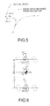
- a controller 2 of a vehicle maneuvering control device to be installed on a vehicle receives signals related to steering angle, yaw rate, vehicle speed, and longitudinal acceleration as detected by a steering wheel angle sensor 3, yaw rate sensor 4, vehicle speed sensor 5, and longitudinal acceleration sensor 6, respectively.
- a signal of a turn signal switch 7 is also input to the controller 2, so as to detect turning operations of the driver (going straight, right turn, left turn).
- a wheel speed sensor 5 may be substitute for the vehicle speed sensor.
- a navigator 8 is connected to the controller 2.
- the navigator 8 provides to the controller 2 such information as point data in map information representing the location and geometry of the road; and road type information, such as highways, ordinary national roads and local roads.
- the width of the road may be input to the controller 2 as map information from the navigator 8.
- a road geometry detector 9 is connected to the controller 2, and detects road width and other data related to road geometry.
- the controller 2 determines whether the vehicle can turn an approaching curve in a stable manner. If required, the controller 2 will warn the driver through a warning device 10, such as, a buzzer, voice warning generator, and warning lamp. Furthermore, if an enforced deceleration is required, the controller 2 will not only set off warning, but also activate a transmission controller 11 to shift the gears down, an engine controller 12 to reduce excessive oil pressure, fuel cut, and throttle full closing (closing control), a brake controller 13 to apply the brakes and increase the braking force.
- a warning device 10 such as, a buzzer, voice warning generator, and warning lamp.
- the controller 2 will not only set off warning, but also activate a transmission controller 11 to shift the gears down, an engine controller 12 to reduce excessive oil pressure, fuel cut, and throttle full closing (closing control), a brake controller 13 to apply the brakes and increase the braking force.
- the navigator 8 consists mainly of a vehicle position detection sensor 8a, an auxiliary memory 8b, a display 8c, a control section 8d, and a processing unit 8e.
- the vehicle position detection sensor 8a gathers running information related to vehicle position.
- the sensor 8a consists mainly of a GPS (Global Positioning System) receiver to receive positioning signals from GPS satellites so as to determine the position of the vehicle; a magnetic sensor to detect the absolute running direction of the vehicle; and a wheel speed sensor composed of an electromagnetic pickup facing an outer periphery of a rotor fixed to the wheel to output a pulse signal when it crosses projections on the outer peripheral of the rotor.
- GPS Global Positioning System
- the auxiliary memory 8b is a CD-ROM device, containing a CD-ROM storing road information, topographical information and other road map information.
- the CD-ROM stores road map information at several hierarchical levels of varying scales as well as road type information such as highways, ordinary national roads, and local roads, and passage conditions information of intersections.
- the road data included in the road map information consists of point data (nodes) input at given intervals of space and line data (link) formed by connecting these nodes.
- the display 8c is a liquid crystal display which displays maps, the vehicle position (the latitude, longitude and altitude), orientation, the position of vehicle on the map, and the optimum routing up to the destination.
- a touch panel as the control section 8d is integrated within the display 8c (liquid crystal display), making it possible to change displaying of the map scale, detailed display of place names, and displays of area information and route guidance.
- the processing unit 8e combines the vehicle running information obtained from the vehicle position detection sensor 8a and the map information read from the auxiliary memory 8b, while making map matching and other processing. The results are fed to the display 8c based on an operating signal sent from the control section 8d, so as to display the present position of the vehicle, its peripheral map, the optimum route to the destination and other information.
- the node data of the road data and the information on node types are output to the controller 2 as required.
- an important function of the road geometry detector 9 is to detect road width.
- the detector 9 consists mainly of a pair of CCD cameras 9a, an image processor 9b and a road width detector 9c.
- the pair of CCD cameras 9a are installed at the right and left sides of the front of the vehicle ceiling at a fixed distance, so as to image the objects outside of the vehicle from different view points. Signals of the passing images taken by the CCD cameras 9a are output to the image processor 9b.
- a pair of stereo images taken by the CCD cameras 9a are fed to the image processor 9b that determines distance information over the entire image filed by way of trigonometric calculations according to the deviations of the positions of objects in each image, so as to generate a distance image showing distance distribution in 3-D.
- the generated 3D-distance image is output to the road width detector 9c.
- the road width detector 9c first recognizes the road being traveled on by providing a histogram processing of the distance distributions of the distance images sent from the image processor 9b. The road width thus calculated is then output to the controller 2 as required.
- the road width detector 9c approximates, for example, lane-dividing lines as broken lines, and judges the area between the left and right broken lines as the traffic lane for the vehicle.
- the road width is calculated from the distance between the left and right broken lines of the traffic lane.
- the road geometry detector 9 detects road geometry to determine the road width and compares the obtained road geometry with the map road geometry data in the navigator 8, and corrects the vehicle position on the map, thereby allowing a more accurate positioning of the vehicle.
- the warning device 10 is a warning means which consists of a chime, buzzer, voice warning generator, warning lamp or combination of these. For example, during warning set-off time, either such a voice warning as "Slow down for the approaching curve" previously recorded in the CD-ROM in the navigator 8 or a buzzer warning is taken, and during enforced deceleration time, the voice warning, the buzzer warning and lighting of the warning lamp are combined. There may be other warning systems, such as selection of two or more voice warnings for just warning time and enforced deceleration time. Color display on the map or voice annunciation may be used for more clearly teaching the driver about the position of the curve for which warning / deceleration control should be taken.
- the transmission controller 11 (deceleration means) makes transmission-related controls such as gear change, lockup of torque converter, and line pressure.
- the transmission controller 11 not only outputs the present gear position to the controller 2, but also makes gear shift-down operation on receiving a signal for commanding a shift-down from the controller 2.
- the engine controller 12 (deceleration means) makes such engine related controls as fuel injection, ignition timing, supercharging pressure, and throttle opening.
- the engine controller 12 not only outputs to the controller 2 supercharging pressure control information, fuel cut information, and throttle opening control information, but also makes supercharging pressure down, fuel cut or throttle full closing operation (closing control) when receiving, respectively, a signal for executing the supercharging pressure down, fuel cut or the throttle full closing (closing control) from the controller 2.
- the brake controller 13 (deceleration means) is connected to a hydraulic unit to make an anti-lock brake control and an automatic brake control.
- the brake controller 13 not only outputs the present brake activation condition to the controller 2, but also, receiving a command signal for brake activation or brake force increase, executes brake activation or brake force increasing.
- the controller 2 comprises a vehicle speed change calculator 21, a road surface friction coefficient estimation section 22, a road slope estimation section 23, a curve geometry detector 24, a data reduction section 25, an allowable lateral acceleration setting section 26, a referential allowable approaching speed setting section 27, an allowable deceleration setting section 28, a warning speed calculation / memory section 29, a speed calculation / memory section 30, a control execution determination section 31, a warning judgment output section 32, a deceleration judgment output section 33 and a selection section 34.
- the above vehicle speed change calculator 21 calculates a change rate of vehicle speed for each setting time based on the vehicle speed output from the vehicle sensor 5. The calculation results are output to the road slope estimation section 23 and the control execution determination section 31.
- the road surface friction coefficient estimation section 22 estimates road surface friction coefficient ⁇ using, e.g., the method disclosed by the applicant of the present invention in the Japanese Patent Laid-open No. 2274/ 1996, based on the vehicle speed V from the vehicle speed sensor 5, the steering angle ⁇ f from the steering wheel angle sensor 3 and the yaw rate ⁇ from the yaw rate sensor 4.
- the estimated road surface friction coefficient ⁇ is output to the allowable lateral acceleration setting section 26 and the allowable deceleration setting section 28.
- a change rate ⁇ of the estimated road surface friction coefficient ⁇ is calculated. If the change rate ⁇ is larger than a given value, an allowable deceleration XgLim, an allowable lateral acceleration ayln, a referential allowable approaching speed Vpn, a warning speed VA, and a deceleration speed VB (each to be described later) are recalculated before starting the control.
- the estimation method of the road surface friction coefficient ⁇ compares a yaw rate response based on the equation for the vehicle's motion and an actual yaw rate so as to estimate online the coefficient while taking the equivalent cornering power of tire as unknown parameter.
- the road surface friction coefficient ⁇ is calculated by the parameter adjustment law according to the following adaptive control theory:
- An equation for the vehicle's lateral motion is established.
- the cornering force may make a response essentially like a first-order lag for the side slip angle of tires, but if this lag may is neglected, thus obtaining the following expressions (4) and (5):
- Kf and Kr are the cornering powers of longitudinal wheels, respectively, ⁇ f and ⁇ r are the side slip angles of them.
- the foregoing equations of motion represented with conditional variables, to develop the adaptive control theory by establishing the parametric adjustment law may allow for estimation of various parameters. Then, the cornering power of the actual vehicle is determined from the estimated parameters of the actual vehicle.
- the body mass and yawing inertial moment of the vehicle may be used as the estimated parameters, but in this case let us assume that these are constant and only the cornering power of vehicle's tires may vary.
- the factors influencing the cornering power of the tires may be nonlinearity of lateral force in respect to slip angle, influence of the road surface friction coefficient ⁇ , and influence of load displacement.
- the cornering powers Kf and Kr of the longitudinal wheels in a non-linear range can be estimated by calculating the above expressions giving various values to the vehicle speed V, the steering angle ⁇ f and the yaw rate ⁇ . Then, the road surface friction coefficient ⁇ can be calculated based on a comparison of the estimated cornering powers Kf and Kr respectively with, e.g., the ones on a high friction coefficient road, thereby resulting in setting of a more accurate estimation of the road surface friction coefficient ⁇ in a non-linear range.
- the road slope estimation section 23 calculates the road slope SL (%) using the following expression (10), based on the longitudinal accelerations given from the longitudinal acceleration sensor 6 and a change rate (m/s 2 ) of the vehicle speed for each setting time calculated by the vehicle speed change calculator 21:
- Road slope (longitudinal acceleration - vehicle speed change rate /g) ⁇ 100 where g (m/s 2 ) is the gravitational acceleration, and (+) is a climbing direction of road slope.
- a change rate ⁇ SL of the estimated road slope SL is calculated.
- a given value such data as an allowable deceleration XgLim, an allowable lateral acceleration ayln, a referential allowable approaching speed Vpn, a warning speed VA and a deceleration speed VB (to be described later) are recalculated, before starting control.
- the road slope SL can be calculated using an engine output torque (N-m), a torque ratio of the torque converter (in the case of automatic transmission vehicle), a transmission gear ratio, a final gear ratio to be used, a radius of tire (m), a running resistance (N), a mass of vehicle (kg), a vehicle speed change rate (m/s 2 ), and the gravitational acceleration g (m/s 2 ):
- Road slope SL tan (sin -1 (((engine output torque ⁇ torque ratio of torque converter ⁇ transmission gear ratio ⁇ final gear ratio/radius of tire) - running resistance)/ mass of vehicle - vehicle speed change rate) /g)) ⁇ 100) ⁇ (((engine output torque ⁇ torque ratio of torque converter ⁇ transmission gear ratio ⁇ final gear ratio/radius of tire) - running resistance)/ mass of vehicle - vehicle speed change rate) /g)) ⁇ 100) ⁇ (((engine output torque ⁇ torque ratio of torque converter ⁇ transmission gear ratio ⁇ final gear ratio/radius
- the road slope SL may be calculated based on altitude data obtained from the navigator 8, or based on road geometry data obtained from the road geometry detector 9.
- the foregoing road slope SL calculated by the road slope estimation section 23 is output to the allowable lateral acceleration setting section 26 and the allowable deceleration setting section 28.
- the curve geometry detector 24 is provided not only with point data (nodes) representing the roads in the map information and road type information, i.e., highway, ordinary national road or local road from the navigator 8, but also with the road width information from the road geometry detector 9. Receiving the input information, the curve geometry detector 24 calculates the curve data for every node within a set distance (forward control range, e.g., V 2 /( ⁇ ⁇ g) assuming twice stop distance under ⁇ ⁇ g deceleration as curve detection range) ahead of the vehicle, so as to output to the data reduction section 25.
- forward control range e.g., V 2 /( ⁇ ⁇ g) assuming twice stop distance under ⁇ ⁇ g deceleration as curve detection range
- the curve geometry detector 24 comprises a three-node detection section 24a, a Pn-1Pn distance calculator 24b, a Pn Pn+1 distance calculator 24c, a long-short judgment section 24d, a mid-point calculator 24e, a mid-point same distance point calculator 24f, a radius calculator 24g and a correction section 24h.
- the three-node detection section 24a reads three nodes located at given intervals in the travelling direction of the vehicle or on the road selected by the driver, successively (from a node closer to the vehicle) as the first node Pn-1, the second node Pn and the third node Pn+1, from the road nodes input from the navigator 8.
- the positional information of the first and second nodes Pn-1 and Pn are output to the Pn-1Pn distance calculator 24b, and the positional information of the second and third nodes Pn and Pn+1 are output to the PnPn+1 distance calculator 24c.
- Pn-1, Pn, and Pn+1 are represented by (Xn-1, Yn-1), (Xn, Yn), and (Xn+1, Yn+1), respectively.
- the representative node of the curve is Pn. Therefore, the curve data of points P1, P2, ..., and Pn are calculated by the combination of (P0, P1, P2), (P1, P2, P3), ..., and (Pn-1, Pn, Pn+1), respectively.
- the Pn-1Pn distance calculator 24b calculates a straight distance connecting Pn-1 and Pn based on the positional information of Pn- 1 and Pn input from the three-node detector 24a, so as to output the straight distance to the long-short judgment section 24d and the correction section 24h.
- the PnPn+ 1 distance calculator 24c calculates a straight distance connecting Pn and Pn+1 based on the positional information of Pn and Pn+1 input from the three-node detector 24a, and outputs the straight distance to the long-short judgment section 24d and the correction section 24h.
- the long-short judgment section 24d compares the straight distance connecting Pn-1 and Pn input from the Pn-lPn distance calculator 24b and the straight distance connecting Pn and Pn+1 input from the PnPn+1 distance calculator 24c, so as to judge which is shorter. Every data (position, distance) for the shorter straight distance is output to the mid-point calculator 24e and the correction section 24g, while every data (position, distance) for the longer straight distance is output to the mid-point same distance point calculator 24f.
- the mid-point calculator 24e Based on the every data (position, distance) for the shorter straight line input from the long-short judgment section 24d, the mid-point calculator 24e not only calculates half of the shorter straight distance, but also determines the mid point position on the shorter straight line.
- the shorter straight line is the straight line connecting Pn-1 and Pn
- every data calculated by the mid-point calculator 24e is output to the mid-point same distance point calculator 24f and the radius calculator 24g.
- the mid-point same distance point calculator 24f determines a mid-point same distance point at the position at half the distance of the shorter straight line apart from Pn on the longer straight line.
- the longer straight line is the line connecting Pn and Pn+1, and let us represent the mid-point same distance point by Pn, n+1 (Xn, n+1 , Yn, n+1).
- the positional data of the mid-point same distance node Pn, n+1 calculated by the mid-point same distance point calculator 24f is output to the radius calculator 24g.
- the radius calculator 24g determines as the central position "On" of the emerging curve on the road the position of the crossing point of a line that crosses the shorter straight line (here, Pn-1 Pn) at right angle with each other at the mid-node Pn-1, n and a line that crosses the longer straight line (here, Pn Pn+1) at right angle with each other at the mid-point same distance node Pn, n+1. Then, based on the determined central position "On", the radius calculator 24g calculates the radius of curvature Rn of the curve. The calculation results are output to the correction section 24h.
- Xn-1, n + M ⁇ (Yn - Yn-1) Xn, n+1 + N ⁇ (Yn+1 - Yn)
- Yn-1,n + M ⁇ (Xn-1 - Xn) Yn, n+1 + N ⁇ (Xn - Xn+1)
- N ((Xn-1 - Xn) ⁇ (Xn-1, n-Xn, n+1) + (Yn-1 - Yn) ⁇ (Yn-1, n - Yn, n+1))/ (Xn-1 ⁇ Yn+1 - Xn+1 ⁇ Yn-1 - Xn-1 ⁇ Yn+Xn Yn-1 - Xn ⁇ Yn+1 + Xn+1 ⁇ Yn)
- Rn ((Xn - Xn- 1) ⁇ (Yn+1 - Yn) - (Xn+ - Xn) ⁇ (Yn - Yn-1)) /
- the case when the radius of curvature Rn is positive means a left turn and the case when the radius of curvature Rn is negative means a right turn.
- the correction section 24h calculates the difference Deln between the radius of curvature Rn obtained by the radius calculator 24g and the distance Lon from the curve center position On to the second node Pn.
- the correction section 24h corrects the radius of curvature Rn so that the difference Deln be within the given error value.
- the final curve information for each node includes the position (Xn, Yn) of the representative node Pn of a curve; the distance Ln between node Pn-1 and node Pn; final radius of curvature Rn; curve angles ⁇ n obtained from the angle formed by lines Pn-1 Pn and Pn Pn+1; the distance between the curve starting point Lsn (the intersection point of the line Pn-1 Pn and the perpendicular from the curve center On to the line Pn-1Pn ) and the node Pn-1; and the distance Lssn from vehicle position to each representative node of the curve.
- the error set value depends on road width D and the shorter line distance judged by the long-short judgment section 24d, thereby being represented as ⁇ D. (Here, ⁇ is a constant to be set in accordance with the shorter line distance, hereinafter referred to as a node interval correction factor.)
- a road width obtained from the road geometry detector 9 is to be adopted for the foregoing road width D, but, when the road geometry detector 9 cannot tell any road width, the foregoing road width D may be set based on the road type information to be obtained from the navigator 8.
- the wider the road width D the larger the error set value, thus going toward no correction. This means that, the wider the actual road width, the larger the radius of the curvature Rn.
- the shorter the shorter line distance the larger the node interval correction factor a , thus increasing the error set value to eliminate the chance for correction.
- ⁇ 1. 2
- ⁇ 1. 2
- ⁇ 3.
- FIG. 4 shows a detailed correction to be made by the correction section 24h.
- the vector from Pn-1 to Pn is denoted as B1ve (ve meaning a vector), and the vector from P2 to P3 is denoted as B2ve.
- Deln Lon -
- the irregular nodes from the navigator 8 can be used as it is, thus resulting in simple calculation without data supplement or complex calculations, so that the radius of curvature of a road being traveled on can be determined quickly and accurately.
- the calculated radius of curvature always becomes smaller than the actual radius of curvature, thereby preferable when setting off a proper warning in the warning / deceleration control when approaching a curve.
- Provision of the correction section 24h for the radius of curvature can help an accurate calculation of the radius of curvature.
- the error set value which a variable in accordance with the actual road geometry and the number of node can make calculations more accurate.
- the wider road actually represents the larger radius of curvature, the wider the road width, the larger the error set value, thus eliminating the need or chance for correction.
- a shorter straight line distance results in fine setting of nodes, thus probably representing the road more accurately, so that the shorter the shorter line distance, the larger the error set value, thereby the more eliminating the chance for correction.
- the data reduction section 25 is provided to reduce data (belonging to every node) detected by the curve geometry detector 24 and sends the reduced data for further calculation, to the allowable lateral acceleration setting section 26, the referential allowable approaching speed setting section 27; the warning speed calculation/memory section 29; the deceleration speed calculation/memory section 30; the warning judgment output section 32; and the deceleration judgment output section 33, thus eliminating unnecessary calculations.
- the data reduction section 25 assumes the following four cases to reduce the voluminous curve information only to really needed ones.
- node Pn can be a start point to calculate a total curve angle ⁇ sn independent from the total curve angle ⁇ s(n-1).
- the reason why the deceleration distance is defined as the difference between the radius of curvature Rn and the radius of curvature Rn-1 is as follows:
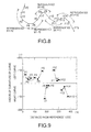
- FIGS. 8, 9 and 10 show an example where the foregoing four cases are applied to actual running :
- FIGS. 9 and 10 show the results of the curve information calculated.
- the radii of curvature of the curves P1 to P 15 were obtained by the curve geometry detector 24 as shown in FIG. 9.
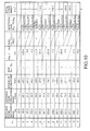
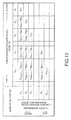
- FIG. 10 is a table showing the results which the data reduction section 25 calculated based on the curve information for each node.
- the case 2 is applied to the route P1 to P2
- the case 3 is applied to the route P2 to P3 and to the route P3 to P4, and therefore, nodes P1, P3 and P4 are neglected.
- nodes P1, P2, P3 and P4 are represented by node P2.
- the case 1 is applied to the route P4 to P5, thus necessitating node P4. But, when the vehicle was running from P3 to P4, P4 has been judged unnecessary, so that node P4 is neglected (or eliminated from this calculation).
- the case 3 is applied to the route P5 to P6, and node P6 is eliminated (or represented by node P5).
- the case 4 is applied to the route P6 to P7 because of turning direction change, thus judging that node P7 is necessary. But, the case 2 is applied to the route P7 to P8, resulting in a judgment that node P7 is unnecessary, so that node P7 is eliminated.
- the case 3 is applied to the route P8 to P9, and P9 is neglected (or represented by node P8).
- the case 4 is applied to the route P9 to P10 because of turning direction change, thus judging that node P10 is necessary. But, the case 2 is applied to the route P10 to P11, resulting in a judgment that node P10 is unnecessary, so that node P10 is eliminated.
- the case 3 is applied to the route P11 to P12, and node P12 is neglected (or represented by node P11).
- the case 4 is applied to the route P12 to P13 because of turning direction change, thus judging that node P13 is necessary. But, the case 2 is applied to the route P13 to P14, resulting in a judgment that node P13 is unnecessary, so that node P13 is eliminated.
- the case 3 is applied to the route P14 to P15, and node P15 is neglected (or represented by node P14).
- the total fifteen nodes are reduced to necessary five nodes, thus resulting in a substantial reduction of calculation and memory volume, as well as a speedy processing.
- the curve detection means comprises the navigator 8, the road geometry detector 9, the curve geometry detector 24 and the data reduction section 25.
- the allowable lateral acceleration setting section 26 comprises a reference value setting section 26a, a vehicle speed correction section 26b, a curve angle correction section 26c, and a road slope correction section 26d.
- the reference value setting section 26a calculates a reference value ayl1n of an allowable lateral acceleration ayln in accordance with the road surface friction coefficient ⁇ .
- the vehicle speed corrected section 26b corrects the reference value aylln to a corrected value ayl2n in accordance with the vehicle speed V.
- the curve angle correction section 26c corrects the corrected value ayl2n to a corrected value ayl3n in accordance with the total curve angle ⁇ sn and the direction of the curve to which node Pn belongs.
- the road slope correction section 26d corrects the corrected value ayl3n in accordance with the road slope SL, to obtain the allowable lateral acceleration ayln.
- the allowable lateral acceleration setting section 26 is constituted as allowable lateral acceleration setting means, and the set allowable lateral acceleration ayln is output to the reference allowable approaching speed setting section 27.
- the safety factor K ⁇ is taken as 0.5 to 1.0 taking into consideration the estimation accuracy of the road surface friction coefficient ⁇ and the vehicle characteristics (e.g., generation of lateral acceleration of 0. 5G is impossible when the road surface friction coefficient ⁇ is 0.5).
- the road slope correction section 26d makes the final correction to be made at the allowable lateral acceleration setting section 26.
- the lateral force to tire becomes maximum when the longitudinal force to tire is zero.
- the vehicle speed is being decelerated with the upward slope so as to have margin, while the vehicle is being accelerated on a downward slope, thus increasing criticality. Therefore, on a downward slope, assuming that the combination of the longitudinal force and the lateral force which can be generated by the tire is constant as a frictional circle, an allowable lateral acceleration ayln less a brake force for traveling the slope at a constant speed is set.
- the reference allowable approaching speed setting section 27 is a means for setting a reference allowable approaching speed Vpn based on the radius of curvature Rn of curve given by the data reduction section 25 and the allowable lateral acceleration ayln given by the allowable lateral acceleration setting section 26.
- Each reference allowable approaching speed Vpn which has been set is output to the warning speed calculation/memory section 29 and the deceleration speed calculation/memory section 30.
- Vpn (ayln ⁇ Rn) 1/2
- the allowable deceleration setting section 28 comprises a reference value setting section 28a and an allowable deceleration correction section 28b to constitute a means for setting a deceleration (allowable deceleration XgLim) which is allowed for a vehicle in accordance with the road conditions including the road surface friction coefficient ⁇ and the road slope SL.
- the allowable deceleration XgLim to be set by the allowable deceleration setting section 28 is output to the warning speed calculation/memory section 29, the deceleration speed calculation/memory section 30, the warning judgment output section 32, the deceleration judgment output section 33 and the selection section 34.
- the coefficient K ⁇ 2 is selected as 0.8 or so.
- the constant axc is previously set by experiment or theoretical calculation, e.g., 5m/s 2 or so.
- the allowable deceleration correction section 28b determines an allowable deceleration XgLim, using the following expression (29): According to this, the allowable deceleration is corrected to be larger taking account of deceleration due to gravity on a climbing slope, thereby to delay warning / deceleration control. Moreover, the allowable deceleration is corrected to be smaller taking account of acceleration due to corrected to be smaller taking account of acceleration due to gravity on a down slope, so as to advance the warning/ deceleration control.
- XgLim XgLim0 + g ⁇ SL/100
- the warning speed calculation/memory section 29 is a means for calculating a reference allowable approaching speed as warning speed VA for warning control based on the allowable deceleration XgLim to be set by the allowable deceleration setting section 28; the reference allowable approaching speed Vpn to be set by the reference allowable approaching speed setting section 27; and the distance Ls between node Pn-1 and node Pn stored at the data reduction section 25.
- each warning speed VA calculated by the warning speed calculation/memory section 29 is stored together with a deceleration speed VB (to be described later), and the stored warning speed VA is fetched to the warning judgment output section 32 as required.
- the warning speed calculation/memory section 29 regards 50% of the attainable deceleration SgLim as a threshold for warning.
- VA ⁇ (VP ⁇ 2 +2 ⁇ (0.5 ⁇ XgLim) ⁇ (L( ⁇ +1)+ ⁇ + L ⁇ )) 1/2
- the deceleration speed calculation/memory section 30 is a means for calculating an allowable approaching speed to be a criterion for deceleration control (as deceleration speed VB) based on the allowable deceleration XgLim set by the allowable deceleration setting section 28; the reference allowable approaching speed Vpn set by the reference allowable approaching speed setting section 27; and the Pn-1 to Pn distance Ln stored in the data reduction section 25. As shown in the table in FIG.
- the deceleration speed VB calculated by the deceleration speed calculation/memory seciton 30 is stored together with the warning speed VA calculated by the warning speed calculation/memory section 29, and the stored data are fetched to the deceleration judgment output section 33 as required.
- the deceleration speed calculation/memory section 30 regards 80% of the allowable deceleration SgLim as a threshold for enforced deceleration.
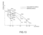
- FIG. 13 is an illustration showing the relationship between the warning speed to be stored in the table shown in FIG. 12 and the deceleration speed. For example, comparison of respective warning speeds plotted on the vertical line at P1 shows that Vp1 ⁇ VA12 ⁇ VA13 ⁇ (VA14 is eliminated) ⁇ VA15. This means that a warming speed force farther node is set larger because of more marginal distance from the reference node P1.
- the data reduction section 25 has already eliminated the data of the node P2
- the data (VA12 / VB12 ⁇ Vp2) for the node P2 in the table is also eliminated. Accordingly, when approaching to node P2, the vehicle makes no control at Vp2, but makes warning control at VA23 and deceleration control at VB23.
- the warning speed VA and the deceleration speed VB calculated based on the allowable deceleration XgLim, the reference allowable approaching speed Vpn and the distance Ln take into account the road surface friction coefficient ⁇ and the road slope SL, a practical control with high reliability and stability can be carried out in accordance with the actual road surface friction coefficient ⁇ and the road slope SL.
- new values for the allowable deceleration XgLim, allowable lateral acceleration ayln, reference allowable approaching speed Vpn, warning speed VA, and speed VB are reset, so as to make an optimum control corresponding to these new data.
- control execution determination section 31 judges the release (OFF) of warning control, the release (OFF) of warning/deceleration control and a switch from deceleration control to warning control, so as to output the judgment results to the warning judgment output section 32 and the deceleration judgment output section 33.
- the warning control :and/or deceleration control is prohibited when the driver operates the turning signal ,switch 7. Furthermore, it can be predicted that the driver makes unusual driving : including sporty driving when the steering angle from the steering angle sensor 3 becomes larger than a predetermined amount. According to the invention, in that case, the warning control and/or deceleration control is prohibited.
- the warning judgment output section 32 can read the distance L1 between the present vehicle position P0 and the closest node P1 from the data reduction section 25; the allowable deceleration XgLim from the allowable deceleration setting section 28; each warning speed VA1 ⁇ (VA1(n+1) ⁇ Vp1) at node P1 from the warning speed calculation/memory section 29; and the vehicle speed V from the vehicle speed sensor 5.
- the warning judgment output section 32 can transform the respective warning speeds VA1 ⁇ (VA1(n+1) ⁇ Vp1) into warning speeds estimated warning speeds VAP at the present vehicle position P0, and can output a signal to the warning device 10 so as to make warning control when the vehicle speed has exceeded the estimated warning speeds VAP.
- the actual execution of the warning control can be prohibited by a command signal from the control execution judgment section 31.
- VAP (VP ⁇ 2 + 2 ⁇ (0.5 ⁇ XgLim) ⁇ (L1 + L2 + ⁇ +L ⁇ )) 1/2
- the deceleration judgment output section 33 can read the distance L1 between the present vehicle position P0 to node P1 from the data reduction section 25; the allowable deceleration XgLim from the allowable deceleration setting section 28; deceleration speeds VB1 ⁇ (VB1(n+1) ⁇ Vp1) at node P1 from the deceleration speed calculation/memory section 30; and the vehicle speed V from the vehicle speed sensor 5.
- the deceleration judgment output section 33 Based on the distance L1 and the allowable deceleration XgLim, the deceleration judgment output section 33 transforms the respective deceleration speeds VB1 ⁇ (VB1 (n+1) ⁇ Vp1) at node P1 into deceleration speeds (estimated deceleration speeds VBP) at the present vehicle position P0. Then, the deceleration judgment output section 33 compares the estimated deceleration speeds VBP and the vehicle speed, to output a deceleration control command signal to the selection section 34 when the present vehicle speed is faster than the estimated deceleration speeds VBP. The execution of deceleration control can be prohibited by a command signal from the control execution judgment section 31. Furthermore, under deceleration control, the deceleration judgment output section 33 outputs a command signal to set off warnings to the effect (turn-on of lamps, voice generation) from the warning device 10.
- the estimated deceleration speed VBP output from the deceleration judgment output section 33 is calculated as follows:
- VBP (VB1 ⁇ 2 + 2 ⁇ (0.8 - XgLim) ⁇ L1) 1/2
- the selection section 34 receives an allowable deceleration XgLim from the allowable deceleration setting section 28 and a command signal of execution (ON) or release (OFF) of deceleration control from the deceleration judgment output section 33. Receiving the command signal of execution of deceleration control, based on the received allowable deceleration XgLim, the selection section 34 selects one of the following control sequences:
- the judgment output means comprises the warning judgment output section 32, the deceleration judgment output section 33 and the selection section 34.
- the warning judgment output section 32 transforms the respective warning speeds VA1 ⁇ (VA1(n+1) ⁇ Vp1) at node P1 into warning speeds (estimated warning speeds VAP) at the present vehicle position P0, and then compares the estimated warning speeds VAP with the present vehicle speed V for judging warning control.
- warning control may be judged as follows: Estimated is a vehicle speed VAP at the nearest forward node P1 after decelerating in accordance with warning deceleration (0. 5 ⁇ Xglim) from the present vehicle position P0. Then, comparison is made between the estimated speed VAP' and the respective warning speeds VA1 ⁇ (VA1(n+1) ⁇ Vp1) at node P1.
- the deceleration judgment output section 33 transforms the respective deceleration speeds VB1 ⁇ (VB1(n+1) ⁇ Vp1) at node P1 into deceleration speeds (estimated deceleration speed VBP) at the present vehicle position P0, and then compares the estimated deceleration speeds VBP with the present vehicle speed V for judging deceleration control.
- deceleration control may be judged as follows: Estimated is a vehicle speed VBP at the nearest forward node P1 after decelerating in accordance with a deceleration (for deceleration purpose) (0. 8 ⁇ Xglim) from the present vehicle position P0.
- VBP' (V 2 -2 ⁇ (0.8 ⁇ XgLim) ⁇ L1) 1/2
- step (hereinafter abbreviated as "S" ) 101 reads the road surface friction coefficient ⁇ estimated by the road surface friction coefficient estimation section 22 based on the vehicle speed V, steering angle ⁇ f and yaw rate ⁇ , to calculate a change rate A ⁇ , and reads the road slope SL calculated by the road slope estimation section 23 based on the longitudinal acceleration from the longitudinal acceleration sensor 6 and on the vehicle speed change rate for every set time calculated by the vehicle speed change calculator 21, to calculate a change rate ⁇ SL.
- the change rates ⁇ and ⁇ SL are compared with given values set for them.
- the given value that is, when either one has largely changed.
- it goes to S103 for recalculation, where every calculation data and memory (allowable deceleration XgLim, allowable lateral acceleration ayIn, reference allowable approaching speed Vpn, warning speed VA, deceleration speed VB and so on) are cleared. Then, it goes to S104.
- S104 reads the present vehicle position P0 from the navigator 8. Then, at S105, new node data ahead of the vehicle, for which allowable deceleration XgLim, allowable lateral acceleration ayln, reference allowable approaching speed Vpn, warning speed VA, and deceleration speed VB have not been calculated yet, are read from the navigator 8 or the memory (in case when the calculation data used have been once cleared on the processor.
- the reference value setting section 26a in the allowable lateral acceleration setting section 26 calculates a reference value atlin for the allowable lateral acceleration ayln in accordance with the road surface friction coefficient ⁇ ;
- the vehicle speed correction section 26b corrects (to a corrected value ayl2n) the reference value ayl1n in accordance with the vehicle speed V;
- the curve angle correction section 26c corrects (to a corrected value ayl3n) the corrected value ayl2n in accordance with the total curve angle ⁇ sn and the turning direction of the curve to which node Pn belongs;
- the road slope correction section 26d corrects the corrected value ayl3n in accordance with the road slope SL so as to determine the final allowable lateral acceleration ayln.
- the reference allowable approaching speed setting section 27 sets the reference allowable approaching speed Vpn based on the the radius of curvature Rn of the curve given from the data reduction section 25 and the allowable lateral acceleration ayln given from the allowable lateral acceleration setting section 26.
- the allowable deceleration setting section 28 sets a reference value XgLim0 based on the road surface friction coefficient ⁇ in the reference value setting section 28a, and adds a correction value based on the road slope SL to the set reference value XgLim0 to obtain an allowable deceleration XgLim.
- the warning speed calculation/memory section 29 calculates and stores a warning speed VA, based on the allowable deceleration XgLim set by the allowable deceleration speed setting section 28; the reference allowable approaching speed Vpn set by the reference allowable approaching speed setting section 27; and each distance Ln between adjacent nodes Pn-1 and Pn stored in the data reduction section 25.
- the deceleration speed calculation /memory section 30 calculates and stores a deceleration speed VB, based on the allowable deceleration XgLim set by the allowable deceleration speed setting section 28; the reference allowable approaching speed Vpn set by the reference allowable approaching speed setting section 27; and each distance Ln between adjacent nodes Pn-1 and Pn stored in the data reduction section 25.
- a forward control range V 2 /( ⁇ ⁇ g) defined to be, e.g., twice the stop distance under ⁇ ⁇ g deceleration as a curve detection range.
- V 2 /( ⁇ ⁇ g) defined to be, e.g., twice the stop distance under ⁇ ⁇ g deceleration as a curve detection range.
- it returns to S105, to repeat the foregoing procedure from S105 to S111, that is, to further detect a new node for calculation.
- it exceeds the forward control range that is, all necessary data within the forward control range are acquired
- the change rate ⁇ or ⁇ SL or both of them are smaller than the set values, that is, the road surface friction coefficient ⁇ or the road slope SL is considered to be constant, the data so far stored is used as it is, so that new data is added to the present data. Therefore, proceeding to S113, the present node P0 is read from the navigator 8. Then, S114 judges whether the distance between the present node P0 and the last read node is within the forward control range.
- S114 judges the distance to be within the forward control range, it returns to S105 to follow the above-described procedure from S105 to S111. Otherwise, when S114 judges the distance to be over the forward control range, it goes directly to S112 to make control based on the data already or presently stored.
- Step S112 judges whether the turning signal switch 7 has been activated. When YES, it goes to S115 to prohibit (OFF) deceleration control, and then goes S116 to prohibit (OFF) warning control. In other words, when the driver has already activated the turning signal switch 7, presupposing that the driver is getting off the road now running and entering a road not described on the map information of the navigator 8, the presently operated warning /deceleration control is prohibited.
- the deceleration judgment output section 33 estimates an estimated deceleration speed VBP at the present node P0 based on each data (each deceleration speed VB1 ⁇ (VB1(n+1) ⁇ Vp1) calculated with reference to node P1.
- the vehicle speed V is compared with the estimated deceleration speed VBP. If the vehicle speed V is over either one of the foregoing estimated deceleration speeds VBP (V ⁇ VBP), it goes to S120.
- S120 judges whether the driver has already been made deceleration over the threshold deceleration (0. 8 ⁇ XgLim) based on a signal from the vehicle speed change calculator 21.
- the warning judgment output section 32 estimates the estimated warning speed VAP at the present node P0 based on each data (warning speeds VA1 ⁇ (VA1 (n+1) ⁇ Vp1)) calculated with reference to node P1.
- S127 judges whether, receiving a signal from the vehicle speed change calculator 21, the driver has already made deceleration over the threshold deceleration (0. 5 ⁇ XgLim).
- the warning control execution (ON) to be made at S123 is accomplished by such a warning device as chime, buzzer, voice warning generator, warning light or their combination.
- the warning control to be performed through S127 is accomplished only by voice warning e.g., "Decelerate for curve", or chime or buzzer sound warning.
- the warning control to be performed through S122 is accomplished only by, for example, chime or buzzer sound warning.
- S129 compares the present vehicle position P0 with the node P1.
- stored node data are shifted (e.g., data stored for node P2 is shifted for to be data for node P1, and data stored for node P3 is shifted to be data for node P2) , and then the program is terminated.
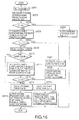
- FIG. 16 is a flow chart showing the program of deceleration control which the selection section 34 carries out when receiving a deceleration control execution signal from the deceleration judgment output device 33:
- the program starts when receiving the deceleration control execution signal.
- S201 sets a deceleration Dt which is the target of deceleration.
- a deceleration D1 achieved by executing supercharging pressure down and fuel cut by the engine controller 12 is calculated.
- comparison between the foregoing target deceleration Dt and the above deceleration D1 is made.
- S205 calculates a deceleration D2 to be expected when the engine controller 12 executes, in addition to the supercharging pressure down and fuel cut throttle closing.
- the program goes to S206, where comparison is made between the target deceleration Dt and the above deceleration D2.
- S209 selects the lowest stage to which gear shift-down can be made by the transmission controller 11, and then the program goes to S210, where it is judged whether the selected gear shift-down is possible.
- S211 calculates a deceleration D3 that is obtained when the engine controller 12 executes supercharging pressure down, fuel cut and closing of the throttle, and the transmission controller 11 executes gear change to the possible lowest stage. Furthermore, the program goes to S212, where the calculated deceleration D3 is compared with the target deceleration Dt.
- the engine controller 12 executes supercharging pressure down, fuel cut, closing of the throttle valve, the transmission controller 11 executes gear shift-down (using the present selected gear shift stage in the case of jump from S210), and the brake controller 13 executes brake force boosting, to terminate the program.
- the selection section 34 selects various combinations of supercharging pressure down, fuel cut, closing of the throttle valve (closing control), gear shift-down and brake force boosting in accordance with necessary deceleration degree, thereby eliminating the possibility of excessive deceleration, thus resulting in a natural and proper deceleration.
- the allowable deceleration setting section 28 sets the reference value XgLim0 in accordance with the actual road surface friction coefficient ⁇ in the reference value setting section 28a, the road surface friction coefficient ⁇ can be well incorporated into the control, thus achieving an optimum vehicle maneuvering control.
- the allowable deceleration setting section 28 not only adds a correction for braking distance variance due to road slope SL by its allowable deceleration correction section 28b, but also corrects the reference value XgLim0 so as to have a larger allowable deceleration on a climbing slope and a smaller allowable deceleration on a down slope for a constant driver's sense of deceleration/acceleration, so that this control can be achieved while giving the driver natural sense.
- the allowable lateral acceleration setting section 26 sets the reference value aylln in accordance with the road surface friction coefficient ⁇ by its reference value setting section 26a, the road surface friction coefficient ⁇ can be well incorporated into the control, thus achieving an optimum vehicle maneuvering control.
- the allowable lateral acceleration setting section 26 corrects the allowable lateral acceleration in accordance with vehicle speed by its vehicle speed correction section 26b, a change in the allowable lateral acceleration in accordance with the vehicle speed is properly corrected, thus resulting in an optimum control.
- the allowable lateral acceleration setting section 26 corrects the allowable lateral acceleration in accordance with the curve angle and the turning direction (left curve, right curve) by its curve angle correction section 26c, an optimum control fully recognizing the difference in forward sighting between left and right curves can be achived when driving on a road having various curving.
- the allowable lateral acceleration setting section 26 corrects the allowable lateral acceleration in accordance with road slope SL by its road slope correction section 26d, the allowable lateral acceleration in accordance with road slope SL can be properly set, thus resulting in optimum control.
- the vehicle maneuvering control device can not only make the optimum control just matching the road condition in a variety of actual roads, but also achive a great deal of benefits allowing natural, practical, reliable and stable maneuvering while taking the effect of the distance up to emerging curves into full consideration.
Landscapes
- Engineering & Computer Science (AREA)
- Transportation (AREA)
- Mechanical Engineering (AREA)
- Chemical & Material Sciences (AREA)
- Combustion & Propulsion (AREA)
- Automation & Control Theory (AREA)
- Control Of Driving Devices And Active Controlling Of Vehicle (AREA)
- Traffic Control Systems (AREA)
- Control Of Vehicle Engines Or Engines For Specific Uses (AREA)
- Auxiliary Drives, Propulsion Controls, And Safety Devices (AREA)
- Navigation (AREA)
- Controls For Constant Speed Travelling (AREA)
- Instructional Devices (AREA)
Claims (14)
- Fahrzeugmanövrier-Steuerungsvorrichtung für ein Fahrzeug, die folgendes aufweist:dadurch gekennzeichnet, daß die Zulässige-Annäherungsgeschwindigkeits-Vorgabeeinrichtung (27) so ausgebildet ist, daß sie auf der Basis der aktuellen Reibungszahl (µ) der Fahrbahn und des Krümmungsradius der Kurve eine zulässige Annäherungsgeschwindigkeit vorgibt, mit der sich das Fahrzeug der Kurve nähern kann, wobei die Annäherungsgeschwindigkeit durch den aktuellen Wert der Fahrbahnneigung (SL) eingestellt wird,eine Fahrbahnoberflächenreibungszahl-Schätzeinheit (22), um aktuelle Werte der Reibungszahl (µ) der Fahrbahnoberfläche zu schätzen;eine Fahrbahnneigungs-Schätzeinheit (23), um aktuelle Werte der Fahrbahnneigung (SL) zu schätzen;eine Kurvendetektiereinrichtung (24), um eine Kurve einer Fahrbahn zu detektieren und Kurvendaten einschließlich eines Abstands zwischen dem Fahrzeug und der Kurve sowie einer physikalischen Größe zu berechnen, die einen Grad der Kurve bezeichnet;eine Zulässige-Verlangsamungs-Vorgabeeinrichtung (28), um die zulässige Verlangsamung vorzugeben, mit der das Fahrzeug unter Berücksichtigung der Fahrbahnbedingungen fahren kann;eine Zulässige-Querbeschleunigungs-Vorgabeeinrichtung (26), um die zulässige Querbeschleunigung vorzugeben, mit der das Fahrzeug unter Berücksichtigung der Fahrbahnbedingungen fahren kann;eine Zulässige-Annäherungsgeschwindigkeits-Vorgabeeinrichtung (27), um auf der Basis einer physikalischen Größe und der zulässigen Querbeschleunigung eine zulässige Annäherungsgeschwindigkeit vorzugeben, mit der sich das Fahrzeug der Kurve nähern kann; undeine Verlangsamungsbeurteilungsgeschwindigkeits-Recheneinrichtung (33), die so ausgebildet ist, daß sie auf der Basis des Abstands, der zulässigen Verlangsamungsgeschwindigkeit und der zulässigen Annäherungsgeschwindigkeit eine Verlangsamungsbeurteilungsgeschwindigkeit berechnet, um zu beurteilen, ob eine aktuelle Geschwindigkeit, mit der das Fahrzeug fährt, verringert werden sollte;
wobei die Reibungszahl (µ) erhalten wird durch Vergleichen einer Gierwinkelreaktion auf der Basis einer Gleichung der Fahrzeugbewegung und eines Ist-Gierwinkels, und wobei die vorgegebene zulässige Annäherungsgeschwindigkeit aktualisiert wird, wenn eine Änderungsrate (Δµ) der Reibungszahl (µ) einen gegebenen Wert überschreitet,
wobei die Fahrbahnneigung (SL) auf der Basis einer Längsbeschleunigung, die von einem Längsbeschleunigungssensor erhalten wird, und einer Änderungsrate einer aktuellen Fahrzeuggeschwindigkeit für jeden Vorgabezeitpunkt berechnet wird, und wobei die vorgegebene zulässige Annäherungsgeschwindigkeit aktualisiert wird, wenn eine Änderungsrate (ΔSL) der Fahrbahnneigung einen gegebenen Wert überschreitet,
daß eine Warnungsbeurteilungsgeschwindigkeits-Recheneinrichtung (29) so ausgebildet ist, daß sie auf der Basis des Abstands, der vorgegebenen zulässigen Verlangsamungsgeschwindigkeit und der vorgegebenen zulässigen Annäherungsgeschwindigkeit eine Warnungsbeurteilungsgeschwindigkeit berechnet, um zu beurteilen, ob dem Fahrer, eine Warnung gegeben werden sollte,
und daß eine Warneinrichtung (10) so ausgebildet ist, daß sie den Fahrer warnt, wenn die aktuelle Geschwindigkeit höher als die Warnungsbeurteilungsgeschwindigkeit ist. - Vorrichtung nach Anspruch 1,
die ferner folgendes aufweist:Verringerungseinrichtungen (11, 12, 13), die so ausgebildet sind, daß sie die aktuelle Geschwindigkeit verringern, wenn die aktuelle Geschwindigkeit höher als die Verlangsamungsbeurteilungsgeschwindigkeit ist. - Vorrichtung nach Anspruch 1 oder 2,
wobei die Verlangsamungsbeurteilungsgeschwindigkeit höher als die Warnungsbeurteilungsgeschwindigkeit ist. - Vorrichtung nach einem der Ansprüche 1 bis 3,
die ferner eine Navigationseinrichtung (8) aufweist, um Informationen über die Fahrbahn zu berücksichtigen, wobei die Kurvendetektiereinrichtung (24) die Kurvendaten auf der Basis der Informationen über die Fahrbahn berechnet. - Vorrichtung nach einem der Ansprüche 1 bis 4,
die ferner eine Fahrbahnkonfigurations-Detektiereinrichtung (9) mit einer Kamera (9a, 9b) aufweist, um durch Bilder der Fahrbahn, die mit der Kamera (9a, 9b) aufgenommen werden, Fahrbahnkonfigurationsdaten zu erhalten, wobei die Kurvendetektiereinrichtung (24) die Kurvendaten auf der Basis der Fahrbahnkonfigurationsdaten modifiziert. - Vorrichtung nach einem der Ansprüche 1 bis 5,
wobei die Kurvendetektiereinrichtung (24) einen Krümmungsradius der Kurve als physikalische Größe berechnet. - Vorrichtung nach einem der Ansprüche 1 bis 6,
wobei die Zulässige-Verlangsamungs-Vorgabeeinrichtung (28) die zulässige Verlangsamungsgeschwindigkeit auf der Basis der Reibungszahl (µ) der Fahrbahn vorgibt. - Vorrichtung nach einem der Ansprüche 1 bis 7,
wobei die Zulässige-Verlangsamungs-Vorgabeeinrichtung (28) die zulässige Verlangsamung auf der Basis der Neigung (SL) der Fahrbahn vorgibt. - Vorrichtung nach einem der Ansprüche 1 bis 8,
wobei die Zulässige-Querbeschleunigungs-Vorgabeeinrichtung (26) die zulässige Querbeschleunigung auf der Basis der Reibungszahl (µ) der Fahrbahn vorgibt. - Vorrichtung nach einem der Ansprüche 1 bis 9,
wobei die Zulässige-Querbeschleunigungs-Vorgabeeinrichtung (26) die zulässige Querbeschleunigung auf der Basis der aktuellen Fahrzeuggeschwindigkeit (V) einstellt. - Vorrichtung nach einem der Ansprüche 1 bis 10,
wobei die Zulässige-Querbeschleunigungs-Vorgabeeinrichtung (26) die zulässige Querbeschleunigung auf der Basis des Winkels der Kurve einstellt. - Vorrichtung nach einem der Ansprüche 1 bis 11,
wobei die Zulässige-Querbeschleunigungs-Vorgabeeinrichtung (26) die zulässige Querbeschleunigung auf der Basis der Richtung einstellt, die das Fahrzeug einschlägt. - Vorrichtung nach einem der Ansprüche 1 bis 12,
wobei die Zulässige-Querbeschleunigungs-Vorgabeeinrichtung (26) die zulässige Querbeschleunigung auf der Basis der Neigung (SL) der Fahrbahn einstellt. - Vorrichtung nach einem der Ansprüche 1 bis 13,
wobei die Verringerungseinrichtungen (11, 12, 13) die aktuelle Geschwindigkeit (V) verringern mit Hilfe von mindestens einer der folgenden Maßnahmen: Herabsetzen der Motorausgangsleistung (12), Herunterschalten (11) und Bremsen (13).
Applications Claiming Priority (3)
| Application Number | Priority Date | Filing Date | Title |
|---|---|---|---|
| JP245788/97 | 1997-09-10 | ||
| JP24578897A JP3485239B2 (ja) | 1997-09-10 | 1997-09-10 | 車両運動制御装置 |
| JP24578897 | 1997-09-10 |
Publications (2)
| Publication Number | Publication Date |
|---|---|
| EP0901929A1 EP0901929A1 (de) | 1999-03-17 |
| EP0901929B1 true EP0901929B1 (de) | 2003-11-26 |
Family
ID=17138846
Family Applications (1)
| Application Number | Title | Priority Date | Filing Date |
|---|---|---|---|
| EP98117156A Expired - Lifetime EP0901929B1 (de) | 1997-09-10 | 1998-09-10 | Vorrichtung zum Steuern der Bewegung eines Fahrzeuges |
Country Status (4)
| Country | Link |
|---|---|
| US (1) | US6208927B1 (de) |
| EP (1) | EP0901929B1 (de) |
| JP (1) | JP3485239B2 (de) |
| DE (1) | DE69819984T2 (de) |
Cited By (2)
| Publication number | Priority date | Publication date | Assignee | Title |
|---|---|---|---|---|
| DE102020100943A1 (de) | 2020-01-16 | 2021-07-22 | Valeo Schalter Und Sensoren Gmbh | Verfahren zur Bestimmung des aktuellen Querneigungswinkels einer Fahrbahn |
| DE102023127573A1 (de) | 2023-10-10 | 2025-04-10 | Dr. Ing. H.C. F. Porsche Aktiengesellschaft | Kraftfahrzeug-Kurvenassistenz-Anordnung |
Families Citing this family (135)
| Publication number | Priority date | Publication date | Assignee | Title |
|---|---|---|---|---|
| DE19848236A1 (de) * | 1998-10-20 | 2000-04-27 | Bosch Gmbh Robert | Verfahren und Vorrichtung zur Begrenzung der Geschwindigkeit eines Fahrzeugs |
| JP3747662B2 (ja) * | 1998-12-07 | 2006-02-22 | トヨタ自動車株式会社 | 車輌の運動制御装置 |
| DE19944333B4 (de) * | 1999-08-04 | 2010-11-11 | Continental Teves Ag & Co. Ohg | Vorrichtung zur Regelung eines Giermoments |
| JP3167987B2 (ja) | 1999-08-06 | 2001-05-21 | 富士重工業株式会社 | カーブ進入制御装置 |
| JP3167989B2 (ja) | 1999-08-10 | 2001-05-21 | 富士重工業株式会社 | カーブ進入制御装置 |
| JP3349120B2 (ja) | 1999-09-09 | 2002-11-20 | 富士重工業株式会社 | カーブ進入制御装置 |
| JP3167990B2 (ja) | 1999-09-14 | 2001-05-21 | 富士重工業株式会社 | カーブ進入制御装置 |
| JP3167993B2 (ja) | 1999-09-21 | 2001-05-21 | 富士重工業株式会社 | 道路形状推定装置及びそれを用いたカーブ進入制御装置 |
| JP3092803B1 (ja) | 1999-09-21 | 2000-09-25 | 富士重工業株式会社 | カーブ進入速度制御装置 |
| JP3391745B2 (ja) * | 1999-09-22 | 2003-03-31 | 富士重工業株式会社 | カーブ進入制御装置 |
| GB0002292D0 (en) * | 2000-02-02 | 2000-03-22 | Jaguar Cars | Motor vehicle dynamic stability control |
| EP1257432B1 (de) * | 2000-02-09 | 2005-05-25 | Continental Teves AG & Co. oHG | Schaltungsanordung und vorrichtung zur regelung und steuerung der fahrgeschwindigkeit eines kraftfahrzeugs |
| DE10008665A1 (de) * | 2000-02-24 | 2001-08-30 | Zahnradfabrik Friedrichshafen | Verfahren zur Steuerung von Antriebssystemen eines Kraftfahrzeugs |
| US6873898B1 (en) * | 2000-06-15 | 2005-03-29 | Continental Teves, Inc. | Vehicle control system utilizing gps data |
| US7375728B2 (en) * | 2001-10-01 | 2008-05-20 | University Of Minnesota | Virtual mirror |
| US6977630B1 (en) * | 2000-07-18 | 2005-12-20 | University Of Minnesota | Mobility assist device |
| DE10047746A1 (de) * | 2000-09-27 | 2002-04-11 | Bayerische Motoren Werke Ag | Verfahren zur Längsregelung eines Fahrzeuges, bei dem Informationen eines Navigationssystems erfasst werden |
| JP3271963B1 (ja) * | 2000-10-26 | 2002-04-08 | 富士重工業株式会社 | 車両の路面摩擦係数推定装置 |
| US6681177B2 (en) * | 2001-01-30 | 2004-01-20 | Rajashri Joshi | Bowing coefficient representation of curvature of geographic features |
| JP2002260190A (ja) * | 2001-02-28 | 2002-09-13 | Fujikura Ltd | 安全運転支援システム |
| USRE46109E1 (en) | 2001-03-29 | 2016-08-16 | Lg Electronics Inc. | Vehicle navigation system and method |
| US6487494B2 (en) * | 2001-03-29 | 2002-11-26 | Wingcast, Llc | System and method for reducing the amount of repetitive data sent by a server to a client for vehicle navigation |
| US8175886B2 (en) | 2001-03-29 | 2012-05-08 | Intellisist, Inc. | Determination of signal-processing approach based on signal destination characteristics |
| US20020143611A1 (en) * | 2001-03-29 | 2002-10-03 | Gilad Odinak | Vehicle parking validation system and method |
| US6591168B2 (en) * | 2001-08-31 | 2003-07-08 | Intellisist, Inc. | System and method for adaptable mobile user interface |
| US6885735B2 (en) * | 2001-03-29 | 2005-04-26 | Intellisist, Llc | System and method for transmitting voice input from a remote location over a wireless data channel |
| US7236777B2 (en) | 2002-05-16 | 2007-06-26 | Intellisist, Inc. | System and method for dynamically configuring wireless network geographic coverage or service levels |
| US20050065779A1 (en) * | 2001-03-29 | 2005-03-24 | Gilad Odinak | Comprehensive multiple feature telematics system |
| JP4628583B2 (ja) | 2001-04-26 | 2011-02-09 | 富士重工業株式会社 | カーブ進入制御装置 |
| US7552008B2 (en) * | 2001-07-18 | 2009-06-23 | Regents Of The University Of Minnesota | Populating geospatial database for onboard intelligent vehicle applications |
| SE0104245D0 (sv) | 2001-12-17 | 2001-12-17 | Scania Cv Abp | A method for a vehicle |
| DE10203511A1 (de) * | 2002-01-30 | 2003-08-07 | Bosch Gmbh Robert | Verfahren und Vorrichtung zur prädiktiven Fahrdynamikregelung bezüglich der Kurvenkontrolle |
| FR2835482B1 (fr) * | 2002-02-04 | 2004-07-09 | Giat Ind Sa | Procede de ralentissement en virage d'un vehicule |
| DE60332124D1 (de) * | 2002-08-06 | 2010-05-27 | Advics Co Ltd | Bewegungssteuervorrichtung für fahrzeug |
| US6970779B2 (en) * | 2002-11-25 | 2005-11-29 | Denso Corporation | Vehicle speed control system and program |
| JP4095460B2 (ja) * | 2003-02-07 | 2008-06-04 | 株式会社堀場製作所 | 業務用車両の運行管理システム |
| DE10333962A1 (de) | 2003-07-25 | 2005-02-10 | Robert Bosch Gmbh | Verfahren zum Betreiben eines Fahrzeugs |
| US8768573B2 (en) * | 2003-08-11 | 2014-07-01 | American Vehicular Sciences, LLC | Technique for ensuring safe travel of a vehicle or safety of an occupant therein |
| DE10346846B4 (de) * | 2003-10-09 | 2013-01-03 | Robert Bosch Gmbh | Datenverarbeitungseinheit für Assistenzeinrichtungen in einem Kraftfahrzeug und Verfahren zur Bereitstellung von aktuellen fusionierten Situationsdaten |
| JP4279112B2 (ja) | 2003-10-15 | 2009-06-17 | 日産自動車株式会社 | 減速制御装置 |
| JP2005119467A (ja) * | 2003-10-16 | 2005-05-12 | Denso Corp | 車両処理システム |
| US7444224B2 (en) * | 2003-11-14 | 2008-10-28 | Nissan Motor Co., Ltd. | Lane departure prevention apparatus |
| US7165008B2 (en) * | 2003-11-21 | 2007-01-16 | Kelsey-Hayes Company | Vehicle anti-rollover monitor using kinetic energy and lateral acceleration |
| JP2005162175A (ja) * | 2003-12-05 | 2005-06-23 | Toyota Motor Corp | 車両の減速制御装置 |
| JP3915774B2 (ja) * | 2003-12-05 | 2007-05-16 | トヨタ自動車株式会社 | 車両の減速制御装置 |
| JP2005164010A (ja) * | 2003-12-05 | 2005-06-23 | Toyota Motor Corp | 車両の減速制御装置 |
| JP4148125B2 (ja) * | 2003-12-09 | 2008-09-10 | 日産自動車株式会社 | 減速制御装置 |
| JP2005226670A (ja) * | 2004-02-10 | 2005-08-25 | Toyota Motor Corp | 車両の減速制御装置 |
| FR2862380B1 (fr) * | 2004-03-22 | 2006-09-08 | Siemens Vdo Automotive | Systeme de navigation pour vehicule automobile |
| JP2005297611A (ja) * | 2004-04-06 | 2005-10-27 | Toyota Motor Corp | 車両の減速制御装置 |
| JP2005306281A (ja) * | 2004-04-23 | 2005-11-04 | Nissan Motor Co Ltd | 減速制御装置 |
| US7751973B2 (en) * | 2004-05-04 | 2010-07-06 | Visteon Global Technologies, Inc. | Curve warning system |
| JP4175291B2 (ja) * | 2004-05-12 | 2008-11-05 | トヨタ自動車株式会社 | 車両の減速制御装置 |
| JP4615899B2 (ja) | 2004-06-07 | 2011-01-19 | 日産自動車株式会社 | 車両用旋回走行制御装置 |
| JP4500126B2 (ja) * | 2004-08-02 | 2010-07-14 | 富士重工業株式会社 | ヨーレートセンサの故障診断装置 |
| JP4466299B2 (ja) | 2004-09-28 | 2010-05-26 | 日本電気株式会社 | 車両用警報装置、車両用警報方法及び車両用警報発生プログラム |
| WO2006042026A1 (en) | 2004-10-07 | 2006-04-20 | Kelsey-Hayes Company | Method for efficiently decelerating a vehicle |
| JP4639997B2 (ja) * | 2005-02-18 | 2011-02-23 | トヨタ自動車株式会社 | 車両の減速制御装置 |
| FR2884311A1 (fr) * | 2005-04-12 | 2006-10-13 | Renault Sas | Procede d'estimation de la pente et du devers d'une route a partir d'un vehicule automobile, et dispositif de mise en oeuvre |
| JP4434101B2 (ja) * | 2005-08-03 | 2010-03-17 | トヨタ自動車株式会社 | 車両用駆動力制御装置 |
| US7266438B2 (en) * | 2005-08-26 | 2007-09-04 | Gm Global Technology Operations, Inc. | Method of assisting driver to negotiate a roadway |
| JP4742818B2 (ja) * | 2005-11-07 | 2011-08-10 | 日産自動車株式会社 | 車両用減速制御装置 |
| JP4696918B2 (ja) * | 2006-01-10 | 2011-06-08 | トヨタ自動車株式会社 | 車両の制御装置 |
| JP4807107B2 (ja) * | 2006-03-02 | 2011-11-02 | 日産自動車株式会社 | 車両用走行制御装置 |
| US7548805B2 (en) | 2006-03-27 | 2009-06-16 | Fujitsu Ten Limited | Vehicle control apparatus, vehicle control method and vehicle slip suppressing apparatus |
| US20070282558A1 (en) * | 2006-06-01 | 2007-12-06 | Denso Corporation | Abnormal condition determining system for steering angle sensor |
| DE102007040539B4 (de) * | 2006-09-04 | 2014-03-27 | Denso Corporation | Fahrzeugsteuersystem |
| JP5114903B2 (ja) * | 2006-09-21 | 2013-01-09 | 日産自動車株式会社 | 車両用運転支援装置 |
| JP5011967B2 (ja) * | 2006-11-09 | 2012-08-29 | トヨタ自動車株式会社 | 車両用駆動力制御装置 |
| EP1930690B1 (de) * | 2006-12-07 | 2009-04-15 | Continental Automotive GmbH | Verfahren und Vorrichtung zur dynamischen Bestimmung der Straßenneigung |
| JP4973174B2 (ja) * | 2006-12-18 | 2012-07-11 | トヨタ自動車株式会社 | 車両用駆動力制御装置 |
| JP4967806B2 (ja) | 2007-05-22 | 2012-07-04 | 株式会社日立製作所 | 経路曲率に応じた車両の速度制御装置 |
| JP5336052B2 (ja) * | 2007-05-28 | 2013-11-06 | 株式会社デンソー | クルーズ制御装置、プログラム、及び目標車速の設定方法 |
| JP4933962B2 (ja) * | 2007-06-22 | 2012-05-16 | 富士重工業株式会社 | 分岐路進入判定装置 |
| JP5061776B2 (ja) * | 2007-08-03 | 2012-10-31 | 日産自動車株式会社 | 車両用走行制御装置および車両用走行制御方法 |
| JP5041946B2 (ja) * | 2007-09-26 | 2012-10-03 | アイシン・エィ・ダブリュ株式会社 | スタビライザ制御装置、スタビライザ制御方法およびスタビライザ制御プログラム |
| US8396623B2 (en) | 2007-09-28 | 2013-03-12 | Fujitsu Ten Limited | Driver recorder and method for setting up the driver recorder |
| JP5257923B2 (ja) * | 2008-01-31 | 2013-08-07 | 株式会社アドヴィックス | 車両の運動制御装置 |
| DE102008020488B4 (de) * | 2008-04-23 | 2012-03-29 | Navigon Ag | Verfahren zum Betrieb einer Einrichtung zur Ermittlung eines Streckenverlaufs |
| US9121716B2 (en) | 2008-05-30 | 2015-09-01 | Here Global B.V. | Data mining in a digital map database to identify insufficient superelevation along roads and enabling precautionary actions in a vehicle |
| US9134133B2 (en) | 2008-05-30 | 2015-09-15 | Here Global B.V. | Data mining to identify locations of potentially hazardous conditions for vehicle operation and use thereof |
| US8688369B2 (en) | 2008-05-30 | 2014-04-01 | Navteq B.V. | Data mining in a digital map database to identify blind intersections along roads and enabling precautionary actions in a vehicle |
| US10648817B2 (en) * | 2008-05-30 | 2020-05-12 | Here Global B.V. | Data mining in a digital map database to identify speed changes on upcoming curves along roads and enabling precautionary actions in a vehicle |
| US8775073B2 (en) | 2008-05-30 | 2014-07-08 | Navteq B.V. | Data mining in a digital map database to identify insufficient merge lanes along roads and enabling precautionary actions in a vehicle |
| US20090299616A1 (en) * | 2008-05-30 | 2009-12-03 | Navteq North America, Llc | Data mining in a digital map database to identify intersections located over hills and enabling precautionary actions in a vehicle |
| US8466810B2 (en) | 2008-05-30 | 2013-06-18 | Navteq B.V. | Data mining in a digital map database to identify intersections located at hill bottoms and enabling precautionary actions in a vehicle |
| US9182241B2 (en) | 2008-05-30 | 2015-11-10 | Here Global B.V. | Data mining in a digital map database to identify unusually narrow lanes or roads and enabling precautionary actions in a vehicle |
| US8698649B2 (en) | 2008-05-30 | 2014-04-15 | Navteq B.V. | Data mining in a digital map database to identify decreasing radius of curvature along roads and enabling precautionary actions in a vehicle |
| EP2135783A1 (de) * | 2008-06-18 | 2009-12-23 | GM Global Technology Operations, Inc. | Verfahren zur Unterstützung des Fahrers eines Kraftfahrzeugs |
| JP5139939B2 (ja) * | 2008-09-25 | 2013-02-06 | 日立オートモティブシステムズ株式会社 | 車両の減速支援装置 |
| JP2010076697A (ja) * | 2008-09-29 | 2010-04-08 | Advics Co Ltd | 車両の速度制御装置 |
| US8886434B2 (en) * | 2009-02-04 | 2014-11-11 | GM Global Technology Operations LLC | Method of operating an electronic stability control |
| US8890747B2 (en) * | 2009-02-25 | 2014-11-18 | GM Global Technology Operations LLC | Longitudinal and lateral velocity estimation using single antenna GPS and magnetic compass |
| CN101866181B (zh) * | 2009-04-16 | 2011-12-14 | 中国农业大学 | 农用机械的导航方法、导航装置和农用机械 |
| US8067829B2 (en) * | 2009-04-29 | 2011-11-29 | Bae Systems Information And Electronic Systems Integration Inc. | System and method for multi-chip module die extraction and replacement |
| JP5363906B2 (ja) * | 2009-08-05 | 2013-12-11 | 株式会社アドヴィックス | 車両の速度制御装置 |
| JP5036787B2 (ja) * | 2009-11-04 | 2012-09-26 | 富士通テン株式会社 | ドライブレコーダ |
| US20110153266A1 (en) * | 2009-12-23 | 2011-06-23 | Regents Of The University Of Minnesota | Augmented vehicle location system |
| DE102010004113B4 (de) * | 2010-01-07 | 2014-11-20 | Continental Automotive Gmbh | Verfahren und Vorrichtung zur Ermittlung eines maximalen Reibungsbeiwerts μmax zwischen einem Reifen und einem Untergrund |
| EP2347940A1 (de) * | 2010-01-25 | 2011-07-27 | Autoliv Development AB | Objektkollisionswarnsystem und Verfahren für ein Motorfahrzeug |
| EP2529972A1 (de) * | 2010-01-29 | 2012-12-05 | Toyota Jidosha Kabushiki Kaisha | Fahrzeugsteuerungsvorrichtung |
| JP5080602B2 (ja) * | 2010-03-19 | 2012-11-21 | 日立オートモティブシステムズ株式会社 | 車両制御装置 |
| US8437936B2 (en) * | 2010-04-09 | 2013-05-07 | Navteq B.V. | Method and system for vehicle ESC system using map data |
| US8630779B2 (en) * | 2010-04-09 | 2014-01-14 | Navteq B.V. | Method and system for vehicle ESC system using map data |
| SI2431712T1 (sl) * | 2010-09-17 | 2013-07-31 | Kapsch Trafficcom Ag | Postopek za izračunavanje dolžine poti, ki jo je opravilo vozilo |
| CN101975577B (zh) * | 2010-09-20 | 2012-08-29 | 北京腾瑞万里科技有限公司 | 导航系统中转弯预警处理方法、设备及导航系统 |
| WO2013011058A1 (de) * | 2011-07-19 | 2013-01-24 | Continental Teves Ag & Co. Ohg | Verfahren zur verbesserung der fahrstabilität |
| JP5887915B2 (ja) * | 2011-12-26 | 2016-03-16 | 日産自動車株式会社 | 車両用運転支援装置及び車両用運転支援方法 |
| US9457802B2 (en) * | 2012-04-06 | 2016-10-04 | Richard Louis Ponziani | Turn signal controlled regenerative braking and decelerative loading |
| CN102636179A (zh) * | 2012-05-11 | 2012-08-15 | 北京赛德斯汽车信息技术有限公司 | 一种车辆导航方法 |
| US9657833B2 (en) * | 2012-08-16 | 2017-05-23 | Jaguar Land Rover Limited | System and method for selecting a driveline gear ratio |
| JP6161942B2 (ja) * | 2013-04-19 | 2017-07-12 | 株式会社デンソーアイティーラボラトリ | カーブ形状モデル化装置、車両情報処理システム、カーブ形状モデル化方法、及びカーブ形状モデル化プログラム |
| US20150203107A1 (en) * | 2014-01-17 | 2015-07-23 | Ford Global Technologies, Llc | Autonomous vehicle precipitation detection |
| SE539444C2 (sv) * | 2014-05-21 | 2017-09-26 | Scania Cv Ab | Förfarande och system för säkert framförande av ett fordon vid kurvkörning |
| SE539778C2 (sv) * | 2014-05-21 | 2017-11-28 | Scania Cv Ab | Förfarande och system för anpassning av ett fordons framförande på en vägbana i samband med kurvkörning |
| KR20170005066A (ko) * | 2014-05-21 | 2017-01-11 | 스카니아 씨브이 악티에볼라그 | 곡선로 주행과 관련하여 도로에서 차량의 운행의 적응화를 위한 방법 및 시스템 |
| CN104554271B (zh) * | 2014-12-08 | 2017-09-12 | 昆明理工大学 | 一种基于参数估计误差的路面坡度和汽车状态参数联合估计方法 |
| JP2016159683A (ja) * | 2015-02-27 | 2016-09-05 | 富士通テン株式会社 | 車両制御装置、車両制御システム、および、車両制御方法 |
| FR3036354A1 (fr) * | 2015-05-20 | 2016-11-25 | Michelin & Cie | Procede de determination d'une vitesse limite de roulage |
| CN105095677B (zh) * | 2015-09-10 | 2018-02-06 | 深圳科隆科技有限公司 | 一种自适应驾驶行为分析方法及其装置 |
| JP6432572B2 (ja) * | 2016-08-22 | 2018-12-05 | トヨタ自動車株式会社 | 表示装置、表示システム |
| JP6253000B1 (ja) | 2016-09-14 | 2017-12-27 | マツダ株式会社 | 車両の制御装置 |
| JP6253001B1 (ja) * | 2016-09-29 | 2017-12-27 | マツダ株式会社 | 車両の制御装置 |
| US10189453B2 (en) | 2016-10-05 | 2019-01-29 | Toyota Motor Engineering & Manufacturing North America, Inc. | Coasting guidance timing and drive force adjustment |
| US9896106B1 (en) | 2016-10-24 | 2018-02-20 | Toyota Motor Engineering & Manufacturing North America, Inc. | Coasting distance determination for coasting assistance system |
| US9898928B1 (en) | 2016-10-25 | 2018-02-20 | Toyota Motor Engineering & Manufacturing North America, Inc. | Coasting guidance timing and learning based on approach lane |
| CN106740868B (zh) * | 2016-12-30 | 2019-03-29 | 东软集团股份有限公司 | 一种车速规划的方法、装置和设备 |
| US10279807B2 (en) * | 2017-02-17 | 2019-05-07 | GM Global Technology Operations LLC | System and method for predicting a possible lane departure when driving a vehicle autonomously or semi-autonomously, and for taking a remedial action to prevent a lane departure |
| JP6753358B2 (ja) * | 2017-05-31 | 2020-09-09 | トヨタ自動車株式会社 | 車両制御装置 |
| US10829099B2 (en) | 2018-05-14 | 2020-11-10 | Ford Global Technologies, Llc | Auto-calibrated brake control for vehicles at low speeds |
| US10926779B1 (en) * | 2019-08-23 | 2021-02-23 | Ford Global Technologies, Llc | Method and system for controlling a vehicle |
| US11654932B2 (en) | 2020-12-28 | 2023-05-23 | Waymo Llc | Architecture for variable motion control envelope |
| JP7744174B2 (ja) | 2021-07-26 | 2025-09-25 | トヨタ自動車株式会社 | 車両用表示装置、車両用表示システム、車両用表示方法及びプログラム |
| TWI797847B (zh) * | 2021-11-24 | 2023-04-01 | 財團法人工業技術研究院 | 路側設備訊息傳輸系統及其方法 |
| GB2623826A (en) * | 2022-10-31 | 2024-05-01 | Continental Autonomous Mobility Germany GmbH | Method and system for controlling a vehicle for travelling on a curved road |
Family Cites Families (8)
| Publication number | Priority date | Publication date | Assignee | Title |
|---|---|---|---|---|
| US5388046A (en) * | 1990-11-22 | 1995-02-07 | Mazda Motor Corporation | Traction controller for a vehicle |
| JP3133770B2 (ja) * | 1991-01-18 | 2001-02-13 | マツダ株式会社 | 自動車の走行システム |
| DE4201142C2 (de) * | 1991-01-18 | 2001-11-29 | Mazda Motor | Fahrgeschwindigkeitsbegrenzungsvorrichtung |
| DE4408745C2 (de) * | 1993-03-26 | 1997-02-27 | Honda Motor Co Ltd | Fahr-Steuereinrichtung für Fahrzeuge |
| JP3366096B2 (ja) * | 1994-02-16 | 2003-01-14 | 本田技研工業株式会社 | 車両の走行制御装置 |
| JPH08205306A (ja) * | 1995-01-27 | 1996-08-09 | Fuji Heavy Ind Ltd | 車両の警報装置 |
| JPH08318765A (ja) * | 1995-05-25 | 1996-12-03 | Hitachi Ltd | 情報化自動車制御装置及び方法 |
| JPH10269499A (ja) * | 1997-03-26 | 1998-10-09 | Mitsubishi Motors Corp | 車両の車速制御装置 |
-
1997
- 1997-09-10 JP JP24578897A patent/JP3485239B2/ja not_active Expired - Lifetime
-
1998
- 1998-09-09 US US09/150,194 patent/US6208927B1/en not_active Expired - Lifetime
- 1998-09-10 DE DE69819984T patent/DE69819984T2/de not_active Expired - Lifetime
- 1998-09-10 EP EP98117156A patent/EP0901929B1/de not_active Expired - Lifetime
Cited By (4)
| Publication number | Priority date | Publication date | Assignee | Title |
|---|---|---|---|---|
| DE102020100943A1 (de) | 2020-01-16 | 2021-07-22 | Valeo Schalter Und Sensoren Gmbh | Verfahren zur Bestimmung des aktuellen Querneigungswinkels einer Fahrbahn |
| WO2021144105A1 (de) | 2020-01-16 | 2021-07-22 | Valeo Schalter Und Sensoren Gmbh | Verfahren zur bestimmung des aktuellen querneigungswinkels einer fahrbahn |
| US12195004B2 (en) | 2020-01-16 | 2025-01-14 | Valeo Schalter Und Sensoren Gmbh | Method for determining the current angle of lateral inclination of a roadway |
| DE102023127573A1 (de) | 2023-10-10 | 2025-04-10 | Dr. Ing. H.C. F. Porsche Aktiengesellschaft | Kraftfahrzeug-Kurvenassistenz-Anordnung |
Also Published As
| Publication number | Publication date |
|---|---|
| US6208927B1 (en) | 2001-03-27 |
| JPH1183501A (ja) | 1999-03-26 |
| JP3485239B2 (ja) | 2004-01-13 |
| DE69819984D1 (de) | 2004-01-08 |
| DE69819984T2 (de) | 2004-09-02 |
| EP0901929A1 (de) | 1999-03-17 |
Similar Documents
| Publication | Publication Date | Title |
|---|---|---|
| EP0901929B1 (de) | Vorrichtung zum Steuern der Bewegung eines Fahrzeuges | |
| JP4037506B2 (ja) | 車両運動制御装置 | |
| EP1818231B1 (de) | Fahrzeugsteuerungssystem | |
| EP1074421B1 (de) | Steuervorrichtung zur Erkennung des Anfangs einer Kurvenfahrt | |
| EP0819912B1 (de) | Fahrzeugfahrzustandsvorhersagevorrichtung und Warnvorrichtung, welche die Vorrichtung verwendet | |
| EP1052610B1 (de) | Informationssystem für Fahrzeug | |
| US8150591B2 (en) | Vehicle travel speed control method | |
| CN101152842B (zh) | 行驶控制装置 | |
| EP0933272B1 (de) | Dynamisches Kraftfahrzeugsteuerungssystem | |
| US20200238980A1 (en) | Vehicle control device | |
| EP1085296B1 (de) | Kurvenannäherungssteuervorrichtung | |
| EP3666612A1 (de) | Fahrzeugsteuerungsvorrichtung | |
| JP3548009B2 (ja) | 車両用走行制御装置 | |
| JPH11115545A (ja) | 車両制御装置 | |
| JP4148125B2 (ja) | 減速制御装置 | |
| JP7684776B2 (ja) | 車両制御装置、車両制御方法、及び車両制御システム | |
| US7512491B2 (en) | Navigation device for a vehicle | |
| JP3120588B2 (ja) | 車両特性変更装置 | |
| JP4094105B2 (ja) | 車両運動制御装置 | |
| JP6982753B2 (ja) | 車両制御装置 | |
| JP2006176062A (ja) | 自動操舵制御装置 | |
| EP4631814A1 (de) | Fahrzeugsteuerungsvorrichtung, fahrzeugsteuerungsverfahren und fahrzeugsteuerungssystem | |
| KR20240049590A (ko) | 자동차의 자동화된 종 방향 안내를 위한 방법 및 장치 | |
| Lee et al. | A simulation study of vehicle curve speed control system | |
| JP2004136868A (ja) | 車両運動制御装置 |
Legal Events
| Date | Code | Title | Description |
|---|---|---|---|
| PUAI | Public reference made under article 153(3) epc to a published international application that has entered the european phase |
Free format text: ORIGINAL CODE: 0009012 |
|
| 17P | Request for examination filed |
Effective date: 19981012 |
|
| AK | Designated contracting states |
Kind code of ref document: A1 Designated state(s): DE GB |
|
| AX | Request for extension of the european patent |
Free format text: AL;LT;LV;MK;RO;SI |
|
| AKX | Designation fees paid |
Free format text: DE GB |
|
| 17Q | First examination report despatched |
Effective date: 20010405 |
|
| GRAH | Despatch of communication of intention to grant a patent |
Free format text: ORIGINAL CODE: EPIDOS IGRA |
|
| GRAS | Grant fee paid |
Free format text: ORIGINAL CODE: EPIDOSNIGR3 |
|
| GRAA | (expected) grant |
Free format text: ORIGINAL CODE: 0009210 |
|
| AK | Designated contracting states |
Kind code of ref document: B1 Designated state(s): DE GB |
|
| REG | Reference to a national code |
Ref country code: GB Ref legal event code: FG4D |
|
| REF | Corresponds to: |
Ref document number: 69819984 Country of ref document: DE Date of ref document: 20040108 Kind code of ref document: P |
|
| PLBE | No opposition filed within time limit |
Free format text: ORIGINAL CODE: 0009261 |
|
| STAA | Information on the status of an ep patent application or granted ep patent |
Free format text: STATUS: NO OPPOSITION FILED WITHIN TIME LIMIT |
|
| 26N | No opposition filed |
Effective date: 20040827 |
|
| PGFP | Annual fee paid to national office [announced via postgrant information from national office to epo] |
Ref country code: GB Payment date: 20050907 Year of fee payment: 8 |
|
| GBPC | Gb: european patent ceased through non-payment of renewal fee |
Effective date: 20060910 |
|
| PG25 | Lapsed in a contracting state [announced via postgrant information from national office to epo] |
Ref country code: GB Free format text: LAPSE BECAUSE OF NON-PAYMENT OF DUE FEES Effective date: 20060910 |
|
| REG | Reference to a national code |
Ref country code: DE Ref legal event code: R082 Ref document number: 69819984 Country of ref document: DE Representative=s name: MEISSNER BOLTE PATENTANWAELTE RECHTSANWAELTE P, DE Ref country code: DE Ref legal event code: R081 Ref document number: 69819984 Country of ref document: DE Owner name: SUBARU CORPORATION, JP Free format text: FORMER OWNER: FUJI JUKOGYO K.K., TOKIO/TOKYO, JP |
|
| PGFP | Annual fee paid to national office [announced via postgrant information from national office to epo] |
Ref country code: DE Payment date: 20170905 Year of fee payment: 20 |
|
| REG | Reference to a national code |
Ref country code: DE Ref legal event code: R071 Ref document number: 69819984 Country of ref document: DE |