EP0902130A2 - Dispositif pour remplacer ou élever un cadre de regard de chaussée pris dans un revêtement d'asphalte ou similaire - Google Patents
Dispositif pour remplacer ou élever un cadre de regard de chaussée pris dans un revêtement d'asphalte ou similaire Download PDFInfo
- Publication number
- EP0902130A2 EP0902130A2 EP98116729A EP98116729A EP0902130A2 EP 0902130 A2 EP0902130 A2 EP 0902130A2 EP 98116729 A EP98116729 A EP 98116729A EP 98116729 A EP98116729 A EP 98116729A EP 0902130 A2 EP0902130 A2 EP 0902130A2
- Authority
- EP
- European Patent Office
- Prior art keywords
- frame
- lifting
- manhole cover
- asphalt surface
- base frame
- Prior art date
- Legal status (The legal status is an assumption and is not a legal conclusion. Google has not performed a legal analysis and makes no representation as to the accuracy of the status listed.)
- Withdrawn
Links
- 239000010426 asphalt Substances 0.000 title claims description 15
- 229910000831 Steel Inorganic materials 0.000 claims description 2
- 239000010959 steel Substances 0.000 claims description 2
- 238000010276 construction Methods 0.000 description 4
- 239000004570 mortar (masonry) Substances 0.000 description 4
- 238000003801 milling Methods 0.000 description 3
- 230000008878 coupling Effects 0.000 description 1
- 238000010168 coupling process Methods 0.000 description 1
- 238000005859 coupling reaction Methods 0.000 description 1
- 238000010586 diagram Methods 0.000 description 1
- 238000005553 drilling Methods 0.000 description 1
- 238000004519 manufacturing process Methods 0.000 description 1
Images


Classifications
-
- E—FIXED CONSTRUCTIONS
- E02—HYDRAULIC ENGINEERING; FOUNDATIONS; SOIL SHIFTING
- E02D—FOUNDATIONS; EXCAVATIONS; EMBANKMENTS; UNDERGROUND OR UNDERWATER STRUCTURES
- E02D29/00—Independent underground or underwater structures; Retaining walls
- E02D29/12—Manhole shafts; Other inspection or access chambers; Accessories therefor
- E02D29/14—Covers for manholes or the like; Frames for covers
- E02D29/1445—Tools for positioning or removing cover frames
Definitions
- the invention relates to a device for Replacing or lifting one in an asphalt surface or the like.
- the Device has a base frame on the upper side a traverse is provided on the for height adjustment several hydraulic cylinders to frame the Manhole cover facing drawbars are arranged, where on lower end of the drawbar a lifting device with several hydraulically extendable and retractable essentially horizontally Spreading arms is arranged, and wherein the device is a Has driving device for moving or moving the same.
- Another device is known from DE 296 05 376 U1, with a milling unit that can be guided concentrically around the frame is, and a lifting device on the inside of the frame non-positively attacks are provided, the Milling unit and the lifting device adjustable in height in one are supported on the frame supporting the asphalt.
- This device is relative complex and heavy device, which negatively affects the Manufacturing and also affects the acquisition costs.
- Excavators or trucks with loading cranes necessary which are also used for Operation of the device provide the necessary oil circuit so that an operation without such a vehicle completely is impossible.
- the invention is therefore based on the object To create device of the specified type with the simple way to cut open the asphalt surface or - is separated with the cranked and conical Manhole cover frame can be gripped, the one Numerous connection options from hydraulic Allows utilities and the relatively inexpensive can be produced.
- the device according to the invention is particularly notable characterized by their simplicity and compactness.
- the integrated Driving device allows the device to be moved without other devices or vehicles.
- Another advantage of the device according to the invention consists in cutting or separating the asphalt surface. Where with the device according to DE 296 05 376 U1 tedious Manhole cover frame must be drilled out with the drill head, is only in the device according to the invention Cutting ring with its cutting edge in the asphalt surface indented and thus separated the same, resulting in a leads to considerable time savings.
- embedded frame of a manhole cover has one Base frame 2 according to the shape of the manhole cover.
- a device 1 with a base frame 2 in a rectangular shape for the corresponding manhole cover shown of course the base frame 2 also can be formed round or in other shapes.
- a cross member 4 On the upper side 3 of the base frame 2 is a cross member 4 provided on the for height adjustment several, preferably three, hydraulic cylinders 5 with to frame the Manhole cover facing drawbar 6 are arranged.
- a lifting device 7 At the lower end of the drawbar 6 is a lifting device 7 with several hydraulically essentially horizontal out and retractable spreading arms 8 arranged.
- the flexible Links 11 are primarily needed when The frame of the manhole covers can be replaced or lifted must have a cranked or conical shape.
- the spreading arms 8 extended or the support wedges 10 in a mortar joint retracted the lower edge of the frame.
- the lie down flexible links 11, the chains, preferably Roller chains, steel cables or the like can be attached to the Edges of the respective offset or cone.
- a cutting ring 12 a circumferential cutting edge 13 directed towards the asphalt surface intended.
- the cutting ring 12 is detachable with the base frame 2 connected.
- the cutting ring 12 has on its top 14 several holding 15 and centering devices 16, whereby support them on the inner edge 17 of the base frame 2 (see Fig. 3).
- the cutting edge 13 runs on the inner edge 18 of the Cutting ring 12, its inner diameter or inner Shape is larger than the outer diameter or the outer shape the frame of the manhole cover.
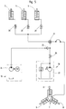
- the cylinders 5 and the spreading arms 8 of the lifting device 7 are via a central hydraulic device 19, on the will be received later.
- the cylinders 5 and the lifting device 7 via valves 20, 21 individually lockable. This has the advantage of being on a downhill slope Road the cylinder 5 can move to different heights because the frame with its lower edge essentially horizontal runs. As a result, the device 1 does not have to be in a horizontal position, which is very difficult could be done by building the base frame 2.
- the frame to the other frame has a driving device 22 on, which is height adjustable.
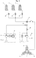
- Fig. 4 shows a hydraulic diagram with the central Hydraulic device 19, which here is a manually operated pump 23 is.
- Fig. 5 is a central hydraulic device 19
- Electromotive pump 24 provided on a clutch 25 of the oil circuit according to FIG. 4 can be connected.
- the manually operated pump 23 shut off via a ball valve 26.
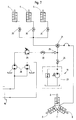
- the Oil circuit of a vehicle e.g. Excavators, Unimog or the like, can be used (see Fig. 7).
- a vehicle e.g. Excavators, Unimog or the like
- the vehicles are usually not sufficient Pressure increase gear pump flow distributor 28, a Booster pump 29 and a shut-off valve 30 may be provided.
- the connection is made via the coupling 25.
- the device 1 by means of the driving device 22 move over the frame of the manhole cover and centrically positioned, the manhole cover being removed from the Framework has been lifted.
- the driving device 22 will then move upwards, whereby the base frame 2 or the cutting ring 12 is placed on the asphalt surface.
- the lifting device 7 into the opening of the frame retracted until the support wedges 10 the lower edge of the Have reached framework.
- the support wedges 10 are by means of the Spreading arms 8 in the mortar joint, below the lower edge of the Frame moves.
Landscapes
- Engineering & Computer Science (AREA)
- Environmental & Geological Engineering (AREA)
- Life Sciences & Earth Sciences (AREA)
- General Life Sciences & Earth Sciences (AREA)
- Mining & Mineral Resources (AREA)
- Paleontology (AREA)
- Civil Engineering (AREA)
- General Engineering & Computer Science (AREA)
- Structural Engineering (AREA)
- Underground Structures, Protecting, Testing And Restoring Foundations (AREA)
- Road Repair (AREA)
Applications Claiming Priority (2)
| Application Number | Priority Date | Filing Date | Title |
|---|---|---|---|
| DE1997140489 DE19740489C2 (de) | 1997-09-15 | 1997-09-15 | Vorrichtung zum Auswechseln bzw. Heben eines in eine Asphaltdecke o.dgl. eingelassenen Rahmens einer Schachtabdeckung |
| DE19740489 | 1997-09-15 |
Publications (2)
| Publication Number | Publication Date |
|---|---|
| EP0902130A2 true EP0902130A2 (fr) | 1999-03-17 |
| EP0902130A3 EP0902130A3 (fr) | 1999-04-28 |
Family
ID=7842379
Family Applications (1)
| Application Number | Title | Priority Date | Filing Date |
|---|---|---|---|
| EP98116729A Withdrawn EP0902130A3 (fr) | 1997-09-15 | 1998-09-03 | Dispositif pour remplacer ou élever un cadre de regard de chaussée pris dans un revêtement d'asphalte ou similaire |
Country Status (2)
| Country | Link |
|---|---|
| EP (1) | EP0902130A3 (fr) |
| DE (1) | DE19740489C2 (fr) |
Cited By (4)
| Publication number | Priority date | Publication date | Assignee | Title |
|---|---|---|---|---|
| DE19912188A1 (de) * | 1999-03-18 | 2000-09-28 | Civieltechnisch Bureau Riedijk | Schachtrahmenheber für den Tief- und Straßenbau |
| ITVI20080285A1 (it) * | 2008-11-28 | 2010-05-29 | Christian Gemmo | Apparecchiatura per estrarre gli anelli dei pozzetti stradali |
| CN114801966A (zh) * | 2022-05-27 | 2022-07-29 | 亚建科技有限公司 | 一种垂直升降式移动拌合楼 |
| CN116873837A (zh) * | 2023-09-08 | 2023-10-13 | 浩立机械(烟台)有限公司 | 一种公路建设井盖机械拆卸设备 |
Families Citing this family (3)
| Publication number | Priority date | Publication date | Assignee | Title |
|---|---|---|---|---|
| DE19945807A1 (de) * | 1999-09-24 | 2001-04-19 | Bartolo Vienna | Gerät zum Anheben und Auswechseln von eingebauten Schachtrahmen |
| DE202012008343U1 (de) * | 2012-08-31 | 2012-09-13 | Frank Straßer | Schieberkappenziehvorrichtung |
| DE202015005865U1 (de) | 2015-08-25 | 2015-09-18 | Nadler Straßentechnik GmbH | Positioniervorrichtung für hydraulische Schachtrahmenheber im Straßenbau |
Citations (1)
| Publication number | Priority date | Publication date | Assignee | Title |
|---|---|---|---|---|
| DE29605376U1 (de) | 1996-03-22 | 1996-06-05 | Stellmach, Paul-Gerd, 32052 Herford | Vorrichtung zum Auswechseln eines in eine Asphaltdecke eingelassenen Rahmens einer Schachtabdeckung |
Family Cites Families (3)
| Publication number | Priority date | Publication date | Assignee | Title |
|---|---|---|---|---|
| DE7008698U (de) * | 1970-03-10 | 1970-11-26 | Helmut Wind | Hydraulischer schachtdeckelringheber. |
| DK172815B1 (da) * | 1994-11-17 | 1999-08-02 | Knud Erik Vester | Fremgangsmåde og aggregat til hævning af brøndkarme |
| DE29608097U1 (de) * | 1996-05-06 | 1996-06-13 | Joch, Hans, 75050 Gemmingen | Hebevorichtung für Schachtrahmen von Regenwassereinläufen |
-
1997
- 1997-09-15 DE DE1997140489 patent/DE19740489C2/de not_active Expired - Fee Related
-
1998
- 1998-09-03 EP EP98116729A patent/EP0902130A3/fr not_active Withdrawn
Patent Citations (1)
| Publication number | Priority date | Publication date | Assignee | Title |
|---|---|---|---|---|
| DE29605376U1 (de) | 1996-03-22 | 1996-06-05 | Stellmach, Paul-Gerd, 32052 Herford | Vorrichtung zum Auswechseln eines in eine Asphaltdecke eingelassenen Rahmens einer Schachtabdeckung |
Non-Patent Citations (1)
| Title |
|---|
| DER FIRMA J. +E. CORDES GMBH, BAUGERCTE FÜR DEN TIEF- UND STRASSENBAU, 57368 LENNESTADT |
Cited By (5)
| Publication number | Priority date | Publication date | Assignee | Title |
|---|---|---|---|---|
| DE19912188A1 (de) * | 1999-03-18 | 2000-09-28 | Civieltechnisch Bureau Riedijk | Schachtrahmenheber für den Tief- und Straßenbau |
| ITVI20080285A1 (it) * | 2008-11-28 | 2010-05-29 | Christian Gemmo | Apparecchiatura per estrarre gli anelli dei pozzetti stradali |
| CN114801966A (zh) * | 2022-05-27 | 2022-07-29 | 亚建科技有限公司 | 一种垂直升降式移动拌合楼 |
| CN116873837A (zh) * | 2023-09-08 | 2023-10-13 | 浩立机械(烟台)有限公司 | 一种公路建设井盖机械拆卸设备 |
| CN116873837B (zh) * | 2023-09-08 | 2023-11-14 | 浩立机械(烟台)有限公司 | 一种公路建设井盖机械拆卸设备 |
Also Published As
| Publication number | Publication date |
|---|---|
| EP0902130A3 (fr) | 1999-04-28 |
| DE19740489A1 (de) | 1999-03-25 |
| DE19740489C2 (de) | 1999-07-15 |
Similar Documents
| Publication | Publication Date | Title |
|---|---|---|
| DE2542432C2 (de) | Drehantrieb für eine Bohranlage sowie Verfahren zum Ausbauen eines Bohrgestänges aus einem Bohrloch | |
| DE3610836A1 (de) | Vorrichtung zum aneinanderfuegen von rohren | |
| DE29612637U1 (de) | Vorrichtung zum Ziehen eines im Erdreich verlegten oder zu verlegenden Rohres | |
| DE19740489C2 (de) | Vorrichtung zum Auswechseln bzw. Heben eines in eine Asphaltdecke o.dgl. eingelassenen Rahmens einer Schachtabdeckung | |
| DE102014011878B4 (de) | Bodenfräsmaschine, Verfahren zum Ausbau und Verfahren zum Einbau einer Fräseinrichtung | |
| DE3238945A1 (de) | Vorrichtung zum setzen von schneestangen oder dgl. | |
| EP0796950A1 (fr) | Méthode et dispositif pour remplacer un cadre de regard disposé dans un revêtement d'asphalte | |
| DE19715775A1 (de) | Hebevorrichtung für Schachtrahmen von Regenwassereinläufen | |
| EP1634848A2 (fr) | Support d'un dispositif de traction pour la pose de canalisations | |
| DE4303944A1 (de) | Hubeinrichtung, insbesondere zum Verlegen von Bordsteinen, Pflasterplatten und dergleichen | |
| DE10203017B4 (de) | Allzweck-Deckelheber für Kanal- und Schachtdeckel | |
| EP0615593A1 (fr) | Support d'ecartement pour canalisations sous-marines | |
| DE102016010089B4 (de) | Positioniervorrichtung für hydraulische Schachtrahmenheber im Straßenbau | |
| DD231922A3 (de) | Vorrichtung zum roden von stubben | |
| DE102016003254A1 (de) | Verfahren zum Ausheben oder Einfahren von Verbauplatten aus einer oder in eine Baugrube, sowie Einrichtung selbst | |
| DE102004048641B4 (de) | Schachtbohranlage mit Hubeinrichtung | |
| DE1811421A1 (de) | Verfahren zum Verlegen von Kabeln und Rohren in Fahrbahnkoerpern | |
| EP3372733B1 (fr) | Dispositif de fixation | |
| DE3312416A1 (de) | Einrichtung zum verlegen von plattenfoermigen elementen | |
| EP3904270B1 (fr) | Dispositif de levage et procédé d'extraction d'un mât ou d'un poteau ancré dans une fondation | |
| DE8212933U1 (de) | Reparaturstand fuer kraftfahrzeugkarosserien | |
| DE2802535A1 (de) | Verfahren zum verlegen oder verlaengern einer rohrleitung und dabei anzuwendende mittel | |
| DE202026100343U1 (de) | Vorrichtung zum Transport sowie zur Montage und Demontage von Schachtrahmen und Straßenablaufrahmen | |
| DE202017104471U1 (de) | Vorrichtung zum Herauspressen eines vertikalen Trägers einer Trägerbohlwand aus dem Erdreich | |
| DE202020103349U1 (de) | System zur Herstellung einer Straßenöffnung in einem Straßenbelag |
Legal Events
| Date | Code | Title | Description |
|---|---|---|---|
| PUAI | Public reference made under article 153(3) epc to a published international application that has entered the european phase |
Free format text: ORIGINAL CODE: 0009012 |
|
| PUAL | Search report despatched |
Free format text: ORIGINAL CODE: 0009013 |
|
| AK | Designated contracting states |
Kind code of ref document: A2 Designated state(s): ES FR NL |
|
| AX | Request for extension of the european patent |
Free format text: AL;LT;LV;MK;RO;SI |
|
| AK | Designated contracting states |
Kind code of ref document: A3 Designated state(s): AT BE CH CY DE DK ES FI FR GB GR IE IT LI LU MC NL PT SE |
|
| AX | Request for extension of the european patent |
Free format text: AL;LT;LV;MK;RO;SI |
|
| 17P | Request for examination filed |
Effective date: 19990519 |
|
| AKX | Designation fees paid |
Free format text: ES FR NL |
|
| REG | Reference to a national code |
Ref country code: DE Ref legal event code: 8566 |
|
| 17Q | First examination report despatched |
Effective date: 20030117 |
|
| STAA | Information on the status of an ep patent application or granted ep patent |
Free format text: STATUS: THE APPLICATION IS DEEMED TO BE WITHDRAWN |
|
| 18D | Application deemed to be withdrawn |
Effective date: 20030401 |