EP0902183B1 - Méthode de fixation des aubes sur le rotor d'une turbine Pelton - Google Patents
Méthode de fixation des aubes sur le rotor d'une turbine Pelton Download PDFInfo
- Publication number
- EP0902183B1 EP0902183B1 EP98810553A EP98810553A EP0902183B1 EP 0902183 B1 EP0902183 B1 EP 0902183B1 EP 98810553 A EP98810553 A EP 98810553A EP 98810553 A EP98810553 A EP 98810553A EP 0902183 B1 EP0902183 B1 EP 0902183B1
- Authority
- EP
- European Patent Office
- Prior art keywords
- pelton
- buckets
- wheel
- cup
- bucket
- Prior art date
- Legal status (The legal status is an assumption and is not a legal conclusion. Google has not performed a legal analysis and makes no representation as to the accuracy of the status listed.)
- Expired - Lifetime
Links
- 239000004033 plastic Substances 0.000 claims description 8
- 229920003023 plastic Polymers 0.000 claims description 8
- 239000000463 material Substances 0.000 claims description 6
- 230000003014 reinforcing effect Effects 0.000 claims description 6
- 238000004873 anchoring Methods 0.000 claims description 4
- 230000005484 gravity Effects 0.000 claims description 3
- 239000002990 reinforced plastic Substances 0.000 claims description 2
- 229910000831 Steel Inorganic materials 0.000 claims 1
- 239000000945 filler Substances 0.000 claims 1
- 230000002401 inhibitory effect Effects 0.000 claims 1
- 229910001092 metal group alloy Inorganic materials 0.000 claims 1
- 239000011241 protective layer Substances 0.000 claims 1
- 239000010959 steel Substances 0.000 claims 1
- 238000005452 bending Methods 0.000 description 7
- XLYOFNOQVPJJNP-UHFFFAOYSA-N water Substances O XLYOFNOQVPJJNP-UHFFFAOYSA-N 0.000 description 5
- 230000008901 benefit Effects 0.000 description 4
- 238000003780 insertion Methods 0.000 description 4
- 230000037431 insertion Effects 0.000 description 4
- 238000004519 manufacturing process Methods 0.000 description 4
- 239000000243 solution Substances 0.000 description 4
- 239000003822 epoxy resin Substances 0.000 description 3
- 239000000835 fiber Substances 0.000 description 3
- 229920000647 polyepoxide Polymers 0.000 description 3
- 229910000851 Alloy steel Inorganic materials 0.000 description 2
- 229920000049 Carbon (fiber) Polymers 0.000 description 2
- PXHVJJICTQNCMI-UHFFFAOYSA-N Nickel Chemical compound [Ni] PXHVJJICTQNCMI-UHFFFAOYSA-N 0.000 description 2
- 239000004917 carbon fiber Substances 0.000 description 2
- 230000008859 change Effects 0.000 description 2
- 238000010276 construction Methods 0.000 description 2
- 238000013461 design Methods 0.000 description 2
- 230000006872 improvement Effects 0.000 description 2
- 238000012423 maintenance Methods 0.000 description 2
- 239000000725 suspension Substances 0.000 description 2
- 238000012546 transfer Methods 0.000 description 2
- VYZAMTAEIAYCRO-UHFFFAOYSA-N Chromium Chemical compound [Cr] VYZAMTAEIAYCRO-UHFFFAOYSA-N 0.000 description 1
- 229920002430 Fibre-reinforced plastic Polymers 0.000 description 1
- 229910052804 chromium Inorganic materials 0.000 description 1
- 239000011651 chromium Substances 0.000 description 1
- 150000001875 compounds Chemical class 0.000 description 1
- 230000003247 decreasing effect Effects 0.000 description 1
- 230000001419 dependent effect Effects 0.000 description 1
- 238000011161 development Methods 0.000 description 1
- 230000018109 developmental process Effects 0.000 description 1
- 238000005553 drilling Methods 0.000 description 1
- 230000000694 effects Effects 0.000 description 1
- 230000005611 electricity Effects 0.000 description 1
- 239000004744 fabric Substances 0.000 description 1
- 239000011151 fibre-reinforced plastic Substances 0.000 description 1
- 230000000762 glandular Effects 0.000 description 1
- 239000003365 glass fiber Substances 0.000 description 1
- LNEPOXFFQSENCJ-UHFFFAOYSA-N haloperidol Chemical compound C1CC(O)(C=2C=CC(Cl)=CC=2)CCN1CCCC(=O)C1=CC=C(F)C=C1 LNEPOXFFQSENCJ-UHFFFAOYSA-N 0.000 description 1
- 238000002347 injection Methods 0.000 description 1
- 239000007924 injection Substances 0.000 description 1
- 238000009434 installation Methods 0.000 description 1
- 229910001234 light alloy Inorganic materials 0.000 description 1
- 229910052751 metal Inorganic materials 0.000 description 1
- 239000002184 metal Substances 0.000 description 1
- VNWKTOKETHGBQD-UHFFFAOYSA-N methane Chemical compound C VNWKTOKETHGBQD-UHFFFAOYSA-N 0.000 description 1
- 238000003801 milling Methods 0.000 description 1
- 238000000465 moulding Methods 0.000 description 1
- 229910052759 nickel Inorganic materials 0.000 description 1
- 238000005498 polishing Methods 0.000 description 1
- 229920000728 polyester Polymers 0.000 description 1
- 229920002635 polyurethane Polymers 0.000 description 1
- 239000004814 polyurethane Substances 0.000 description 1
- 238000010248 power generation Methods 0.000 description 1
- 230000036316 preload Effects 0.000 description 1
- 238000012545 processing Methods 0.000 description 1
- 230000009467 reduction Effects 0.000 description 1
- 230000008439 repair process Effects 0.000 description 1
- 239000004576 sand Substances 0.000 description 1
- 239000007921 spray Substances 0.000 description 1
- VLCQZHSMCYCDJL-UHFFFAOYSA-N tribenuron methyl Chemical compound COC(=O)C1=CC=CC=C1S(=O)(=O)NC(=O)N(C)C1=NC(C)=NC(OC)=N1 VLCQZHSMCYCDJL-UHFFFAOYSA-N 0.000 description 1
Images



Classifications
-
- F—MECHANICAL ENGINEERING; LIGHTING; HEATING; WEAPONS; BLASTING
- F01—MACHINES OR ENGINES IN GENERAL; ENGINE PLANTS IN GENERAL; STEAM ENGINES
- F01D—NON-POSITIVE DISPLACEMENT MACHINES OR ENGINES, e.g. STEAM TURBINES
- F01D5/00—Blades; Blade-carrying members; Heating, heat-insulating, cooling or antivibration means on the blades or the members
- F01D5/30—Fixing blades to rotors; Blade roots ; Blade spacers
- F01D5/3053—Fixing blades to rotors; Blade roots ; Blade spacers by means of pins
-
- F—MECHANICAL ENGINEERING; LIGHTING; HEATING; WEAPONS; BLASTING
- F03—MACHINES OR ENGINES FOR LIQUIDS; WIND, SPRING, OR WEIGHT MOTORS; PRODUCING MECHANICAL POWER OR A REACTIVE PROPULSIVE THRUST, NOT OTHERWISE PROVIDED FOR
- F03B—MACHINES OR ENGINES FOR LIQUIDS
- F03B1/00—Engines of impulse type, i.e. turbines with jets of high-velocity liquid impinging on blades or like rotors, e.g. Pelton wheels; Parts or details peculiar thereto
- F03B1/02—Buckets; Bucket-carrying rotors
-
- Y—GENERAL TAGGING OF NEW TECHNOLOGICAL DEVELOPMENTS; GENERAL TAGGING OF CROSS-SECTIONAL TECHNOLOGIES SPANNING OVER SEVERAL SECTIONS OF THE IPC; TECHNICAL SUBJECTS COVERED BY FORMER USPC CROSS-REFERENCE ART COLLECTIONS [XRACs] AND DIGESTS
- Y02—TECHNOLOGIES OR APPLICATIONS FOR MITIGATION OR ADAPTATION AGAINST CLIMATE CHANGE
- Y02E—REDUCTION OF GREENHOUSE GAS [GHG] EMISSIONS, RELATED TO ENERGY GENERATION, TRANSMISSION OR DISTRIBUTION
- Y02E10/00—Energy generation through renewable energy sources
- Y02E10/20—Hydro energy
Definitions
- the invention relates to a Pelton wheel with a Wheel disc and with separately manufactured cups with Feet that are detachable in the wheel disc Anchoring elements are attached.
- Pelton turbines are found in mountainous areas where a correspondingly high water gradient is available for Power generation used. There is also a Need for compact turbines for the power supply of individual villages in the performance range of, for example 1 megawatt to remote and hard-to-reach areas to supply with electricity.
- the main disadvantages to being outside of industrially managed power plants Making Pelton turbines affordable lies in the high cost of the turbine wheel and in need high quality and trained specialist staff for its Having to use maintenance.
- one-piece Pelton wheels require extensive disassembly, careful repair welds on the cups on most are exposed to wear and tear and then a stress relieving glow of the wheel and further on Polishing and compensating for delay.
- Compound Pelton wheels are in their manufacture and assembly also very expensive.
- This arrangement has the advantage that the nozzle jet generated bending moments in the cup base become smaller and that much of the strength comes from the support shoulders is recorded, which from the same high quality Material consist of how it is made of the wheel disc Strength reasons must be.
- This support allows it, the wall thickness of the cups towards the bottom too small hold and also keep the cup feet slim, so that the mass of a full cup part is small fails and thus relatively simple securing elements to accommodate the generated by the cup parts Centrifugal forces are possible.
- Another improvement to simplify the Securing elements consist in the choice of light ones Materials for the cups. So bring out mugs Plastic, fiber reinforced plastic or Light alloys further reduce the Centrifugal forces on the cup feet. Leave plastic cup for example in high dimensional accuracy and inexpensive to manufacture in a mold.
- Another improvement is a radial one Push in with a swivel for the cups provided.
- the wheel disc is on its periphery with a radial recess, so that in pairs Arranged support shoulders arise throughout the room usable from the recess for reinforcing ribs on the cup base is the centering and lateral support of the Serve cups on the wheel disc and at the same time the Increase the bending stiffness of the cup base.
- locking bolts can be mounted across the wheel disc be attached that only with a portion of their Apply circumference to the cup feet and these against Secure falling out.
- the ribs can be along the The puncture so far that it is in assembled position in the recess if necessary under a predetermined preload touch.
- Another measure can be the puncture slightly conical to fit in with conically shaped reinforcing ribs a light Generate press fit.
- cup base is cylindrical and like a Bucket attachment axially in a suitable recess in the To insert wheel disc, whereby by pre and Recesses also creates a direct attachment.
- Another advantage is that all the essentials Mass are determined by the wheel disc and that the Mounting or changing a cup on one fully installed wheel disc by a Average mechanic can be made.
- the special type of suspension and support of the Mug allows lighter and mechanically weaker Materials than it is the material of the wheel disc, too use. So show cups made of fiber or fabric-reinforced plastics, such as fabric reinforced epoxy resins, very reasonable Results. Carbon fibers, glass fibers can also be used as fibers or plastic fibers can be used.
- plastics can for example epoxy resin, polyester or Polyurethane can be used.
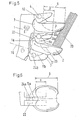
- FIGs 1, 2, 3 and 4 is a first Embodiment shown.
- a wheel disc 1 for one Pelton wheel is centered on its periphery with a radial recess 10 provided. From the side walls limit this recess 10 is a contour worked out that a relatively thin cup base 3 corresponds, with the cup base the lowest point from Puncture 10 protrudes on both sides to close foot 3 itself to lead.
- the cup base 3 there is one in the middle of the puncture 10 matching reinforcing rib 11a, 11b attached, the Height of the pitch of the wheel is adjusted. That rib gives the foot 3 additional flexural rigidity and supports itself when the Pelton wheel is fully equipped, in the circumferential direction on the adjacent ribs.
- the actual cup base 3 corresponds only approximately to that Cup height so that 1 support shoulders 7 on the wheel disc, 7a, 7b stop, the large forces in tangential Can take direction.
- Support shoulders when assembled from the hub side Cup edge 8 in the radial direction approximately up to Project half of the radial cup width 9 outwards, a large part of the on the cups 2 by one Pressure forces delivered directly to the nozzle jet Support shoulders 7, 7a, 7b passed and arise reduced bending moments at the cup base 3.
- the larger the Distance "a" of a support shoulder 7, 7a, 7b from hub-side edge 8 of the cup is chosen the more the bending moments to be compensated for are less Cup. A low cup and foot height is enough to compensate for these bending moments.
- cup 2 and foot 3 decreased, resulting in easier suspension and compensation of the Centrifugal forces.
- Cup 2 made of a carbon fiber reinforced epoxy resin manufactured, which leads to an alloy steel further reduction of centrifugal forces.
- the wheel disc consists of a forged alloy steel with 13% Chromium and 4% nickel, as is usual for water turbines is.
- FIGS 6 Another exemplary embodiment is shown in FIGS 6 shown. It is different from the first example in that to secure the cup base 3 against Falling out is designed as a hook 22, which in a Insertion direction 23 additionally during radial insertion must be swiveled around the wheel disc To reach back shoulder 18, and that too each reinforcing rib 11a, 11b one by one Support shoulder 7 axially inserted bolt 12 as Securing element 4 on a holding surface 24a, 24b is applied. The ribs 11a, 11b do not touch any neighboring ribs 11b, 11a.
- a change in the angular position 16 of the Support surfaces 17 on the support shoulders 7 relative to The center of the wheel disc therefore does not force basically new cups 2, but only for Sectional pivoting of the contour for the Cup holder and to remove other holding surfaces 24a, 24b on the reinforcing ribs 11a, 11b.
- Such one Concept allows it with a one size cup Wheel disks 1 of different diameters too equip and take an angular position 16, the one optimal injection direction of a jet 20 under corresponds to these circumstances. That way, with a whole design field is covered in just a few cup sizes become and at the same time because of the larger ones Cup piece numbers lower the cost per cup. This especially applies when the shape of the cup by pouring into molds because the Molding cost share inversely proportional to the manufactured Number of cups. Cup made of plastic or light metal can be inexpensive in this regard.
- Figure 7 shows an embodiment in which the cup 2 in have cylindrical cup feet 3 in the axial direction, those with holding surfaces 24c, 24d on counter shoulders 18a, 18b the wheel disc 1.
- the cups are axial Direction used and centered by a Centering screw 27 secured in an elongated hole 28th engages on the bottom of the cup 6.
- a part of Support surface 17 is offset in the form of a step to To produce counter shoulder 18b.
- FIGS. 8, 9 and 10 Solution Such a simplified one is shown in FIGS. 8, 9 and 10 Solution shown.
- Holding surfaces 24 and counter shoulders 18 are circular cylindrical in the axial direction Surfaces 29 with a center 30.
- the cup 2 is still retracted by one Angle 34 pivotable about this center 30 so that Cup with a swivel on a tarpaulin Support surface 17 of the support shoulder 7 can rest.
- This division into circular cylindrical surface 29 and flat support surface 17 allows easy processing the wheel disc by drilling and milling.
- An approximate one Center position of the cup edge in the axial direction achieved by a locking screw 32 which in a Pocket 35 can be used on the support shoulder 7 and the Press cup 2 onto support shoulder 17.
- the exact The middle position of the cup 2 should be in the range of Centimeter millimeters relative to the jet should be the same. at a replacement of the cup 2 with the wheel disc installed 1 therefore becomes one that marks the center of the glandular ray Display device on the nozzle in a repeatable Clamping inserted and one cup after the other crazy.
- the side play of the retaining screw 32 in The level of the contact surface is so large that after loosening the retaining screw by knocking on the side the displayed center position on the cup base is adjustable and be secured by tightening the retaining screw 32 can.
- a simple, marking display device results with a LASER that can be clamped on the nozzle POINTER. Because of the contactless but precise convinced anyone can mark the parallel light beam Cup set without loosening the jig become.
- the retaining screw 32 secures the cup 2 against Detachment from the support surface 17.
- An enlargement of the Contact force between cup 2 and support surface 17 results if the center of gravity 31 of the cup 2 is one Distance 33 above an extended connecting line 36 lies, which is the center M of the wheel disc 1 with the Center 30 for the pivotable cup base 3 connects.
- the centripetal force is generated at the center of gravity 3, a moment in the direction of rotation that the Press the cup against the support surface 17.
- the advantage of this design is that, despite the interchangeability of the cups, the cup division D 1 / B 2 can be reduced to a value of around 2.5.
Landscapes
- Engineering & Computer Science (AREA)
- Mechanical Engineering (AREA)
- General Engineering & Computer Science (AREA)
- Chemical & Material Sciences (AREA)
- Combustion & Propulsion (AREA)
- Table Devices Or Equipment (AREA)
- Turbine Rotor Nozzle Sealing (AREA)
Claims (17)
- Roue Pelton munie d'un disque de roue (1) ayant des godets (2) individuels, fabriqués séparément, munis de pieds (3) fixés de façon désolidarisable dans le disque de roue (1) à l'aide d'éléments d'ancrage (4), caractérisée en ce que les godets (2) sont soutenus, sur leur face arrière (6), en direction tangentielle par un épaulement d'appui (7) du disque de roue, qui fait saillie vers l'extérieur en direction radiale d'une distance "a" par rapport au bord (8) côté moyeu des godets, afin de capter les efforts agissant sur les godets et produits par un jet de buse.
- Roue Pelton selon la revendication 1, caractérisée en ce que les épaulements d'appui font saillie radialement vers l'extérieur, chacun d'une distance "a" supérieure à un tiers de l'envergure (9) radiale du godet, en se projetant plus loin que le bord (8) côté moyeu des godets (2).
- Roue Pelton selon la revendication 1 ou 2, caractérisée en ce que les godets (2) peuvent être insérés par leurs pieds (3) en direction radiale (5) dans le disque de roue (1).
- Roue Pelton selon la revendication 3, caractérisée en ce que, lors de l'insertion radiale des godets (2), il faut en plus effecteur un pivotement dans le plan transversal par rapport à l'axe de roue.
- Roue Pelton selon l'une des revendications 1 à 4, caractérisée en ce que le disque de roue (1) présente sur sa périphérie une entaille radiale (10) pour le centrage des pieds de godet, et en ce que des épaulements d'appui (7a, 7b) sont disposés par paires à gauche et à droite de l'entaille (10).
- Roue Pelton selon l'une des revendications 1 à 5, caractérisée en ce que les godets (2) présentent sur leurs pieds une nervure de renforcement (11a, 11b) guidée dans l'entaille (10) du disque de roue.
- Roue Pelton selon l'une des revendications 1 à 6, caractérisée en ce que sont utilisés comme éléments d'ancrage (4) des boulons (12) disposés transversalement par rapport au disque de roue (1), boulons mis en appui sur les pieds de godet (3) par une zone partielle (13) de leur périphérie et assurant ceux-ci contre toute expulsion.
- Roue Pelton selon la revendication 1 ou 2, caractérisée en ce que les pieds de godet (3) présentent des faces (24c, 24d, 6) d'allure cylindrique en direction axiale et sont susceptibles d'être introduits en direction axiale dans le disque de roue, dans un but de fixation.
- Roue Pelton selon la revendication 8, caractérisée en ce que les pieds de godet (3) reposent sur des faces (29) cylindriques à section circulaire et sur des faces d'appui (17) planes sur le disque de roue (1).
- Roue Pelton selon la revendication 9, caractérisée en ce qu'un godet (2), à l'état introduit axiale ment, est susceptible de pivoter d'un angle (34) prédéterminé autour du centre (30) des faces (29) cylindriques à section circulaire et est susceptible d'être pressé sur la face d'appui (17) à l'aide d'un élément de fixation (32).
- Roue Pelton selon la revendication 8 ou la revendication 9, caractérisée en ce que le centre de gravité (31) des godets (2) est situé, en observant dans le sens inverse du sens de rotation de la roue Pelton, à une distance (33), sur une droite de liaison prolongée tracée entre le centre du disque de roue (1) et le centre (30) de la face (29) cylindrique à section circulaire.
- Roue Pelton selon l'une des revendications 1 à 11, caractérisée en ce que les godets (2) sont fabriqués en un matériau à faible poids spécifique par rapport à l'acier, par exemple en une matière synthétique ou bien en un alliage de métal léger.
- Roue Pelton selon la revendication 12, caractérisée en ce que les godets (2) sont fabriqués en une matière synthétique renforcée par des fibres ou bien renforcée par un textile.
- Roue Pelton selon la revendication 12 ou 13, caractérisée en ce qu'au moins sur la face supérieure de godet (14) est appliquée une couche protectrice (15) résistante à l'usure, formée d'un autre matériau.
- Roue Pelton selon la revendication 12 ou 13, caractérisée en ce que sur la face supérieure de godet est insérée dans la surface une charge ayant comme effet d'empêcher l'usure.
- Système de construction pour différentes tailles, échelonnées, de godets de roues Pelton selon l'une des revendications 1 à 15, caractérisé en ce qu'une taille de godet peut être insérée dans des disques de roue à diamètre différents, la position angulaire (16) de la face d'appui (17) des épaulements d'appui (7) par rapport au centre de roue étant pivotée de manière qu'on obtienne pour le godet (2) un angle de calage avantageux, correspondant au diamètre et au nombre de godets, par rapport au jet de buse.
- Turbine Pelton équipée d'une roue Pelton selon l'une des revendications 1 à 13.
Priority Applications (1)
| Application Number | Priority Date | Filing Date | Title |
|---|---|---|---|
| EP98810553A EP0902183B1 (fr) | 1997-09-04 | 1998-06-17 | Méthode de fixation des aubes sur le rotor d'une turbine Pelton |
Applications Claiming Priority (3)
| Application Number | Priority Date | Filing Date | Title |
|---|---|---|---|
| EP97810630A EP0900935A1 (fr) | 1997-09-04 | 1997-09-04 | Fixation d'aubes sur un disque de rotor Pelton |
| EP97810630 | 1997-09-04 | ||
| EP98810553A EP0902183B1 (fr) | 1997-09-04 | 1998-06-17 | Méthode de fixation des aubes sur le rotor d'une turbine Pelton |
Publications (2)
| Publication Number | Publication Date |
|---|---|
| EP0902183A1 EP0902183A1 (fr) | 1999-03-17 |
| EP0902183B1 true EP0902183B1 (fr) | 2003-07-30 |
Family
ID=26148059
Family Applications (1)
| Application Number | Title | Priority Date | Filing Date |
|---|---|---|---|
| EP98810553A Expired - Lifetime EP0902183B1 (fr) | 1997-09-04 | 1998-06-17 | Méthode de fixation des aubes sur le rotor d'une turbine Pelton |
Country Status (1)
| Country | Link |
|---|---|
| EP (1) | EP0902183B1 (fr) |
Families Citing this family (3)
| Publication number | Priority date | Publication date | Assignee | Title |
|---|---|---|---|---|
| FR2817283B1 (fr) | 2000-11-27 | 2003-06-13 | Alstom Power Nv | Composant hydraulique et procede de fabrication d'un tel composant |
| NO333946B1 (no) * | 2011-10-04 | 2013-10-28 | Dynavec As | Skovlforbindelse for et turbinløpehjul |
| CN113478187A (zh) * | 2021-07-19 | 2021-10-08 | 沈阳市盛华特种铸造有限公司 | 一种分体机械组合冲击式转轮的制造方法 |
Family Cites Families (4)
| Publication number | Priority date | Publication date | Assignee | Title |
|---|---|---|---|---|
| FR570124A (fr) * | 1922-11-09 | 1924-04-24 | Neyret Beylier & Piccard Picte | Dispositif de blocage des aubes des turbines pelton |
| CH111442A (fr) * | 1924-08-19 | 1925-09-01 | Fulpius Edmond | Dispositif de fixation d'aubes pour roues de turbine. |
| CH159487A (fr) * | 1931-11-16 | 1933-01-15 | Blum Adolf | Roue Pelton. |
| AT394093B (de) | 1988-11-21 | 1992-01-27 | Efg Turbinen Und Kraftwerksanl | Peltonrad |
-
1998
- 1998-06-17 EP EP98810553A patent/EP0902183B1/fr not_active Expired - Lifetime
Also Published As
| Publication number | Publication date |
|---|---|
| EP0902183A1 (fr) | 1999-03-17 |
Similar Documents
| Publication | Publication Date | Title |
|---|---|---|
| DE19903550C1 (de) | Blattwurzel für Propeller- und Rotorblätter | |
| EP1484475A2 (fr) | Pied d'une aube de compresseur pour moteur d'avion | |
| DE202006007055U1 (de) | Schlegel für eine Zerkleinerungsvorrichtung | |
| EP2286959B1 (fr) | Outil d'ébauchage et de ponçage | |
| DE2953715C2 (de) | Rotierende Mahlscheibe eines Scheibenrefiners | |
| EP0902183B1 (fr) | Méthode de fixation des aubes sur le rotor d'une turbine Pelton | |
| EP3215676B1 (fr) | Attache de rail et plaque intercalaire | |
| WO2011044961A1 (fr) | Frein à disque pour un entraînement azimutal d'une éolienne | |
| EP0900935A1 (fr) | Fixation d'aubes sur un disque de rotor Pelton | |
| EP0250708B1 (fr) | Moule de vulcanisation de pneus | |
| US7040863B2 (en) | Variable pitch rotor blade for shrouded rotors, in particular helicopter rotors | |
| EP2387663B1 (fr) | Turbine à jet libre et procédé de production ou d'installation après coup du roue d'une turbine à jet libre | |
| DE3620097A1 (de) | Rad fuer kraftfahrzeuge | |
| DE1577555A1 (de) | Sandstrahlschleuderradanordnung | |
| DE2642122C2 (de) | Scheibenbremsen-Betätigungskolben | |
| WO2021043938A1 (fr) | Roue de roulement pour vélo | |
| DE3637214A1 (de) | Verbundrad und verfahren seiner herstellung | |
| AT405081B (de) | Laufrad für eine freistrahlturbine | |
| DE3021355A1 (de) | Klemmvorrichtung fuer eine schneideinsatz | |
| DE19650930C2 (de) | Kolben für Brennkraftmaschine | |
| AT400013B (de) | Schleifanordnung | |
| DE1006810B (de) | Pressluftschlagwerkzeug | |
| DE8905025U1 (de) | Bodenbearbeitungsmaschine | |
| DE8009721U1 (de) | Fraeswerkzeug | |
| DD241857B5 (de) | Eisstock |
Legal Events
| Date | Code | Title | Description |
|---|---|---|---|
| PUAI | Public reference made under article 153(3) epc to a published international application that has entered the european phase |
Free format text: ORIGINAL CODE: 0009012 |
|
| AK | Designated contracting states |
Kind code of ref document: A1 Designated state(s): AT CH DE ES FR IT LI |
|
| AX | Request for extension of the european patent |
Free format text: AL;LT;LV;MK;RO;SI |
|
| 17P | Request for examination filed |
Effective date: 19990819 |
|
| AKX | Designation fees paid |
Free format text: AT CH DE ES FR IT LI |
|
| RAP1 | Party data changed (applicant data changed or rights of an application transferred) |
Owner name: VA TECH ESCHER WYSS AG |
|
| RAP1 | Party data changed (applicant data changed or rights of an application transferred) |
Owner name: VA TECH HYDRO GMBH & CO. |
|
| GRAH | Despatch of communication of intention to grant a patent |
Free format text: ORIGINAL CODE: EPIDOS IGRA |
|
| GRAH | Despatch of communication of intention to grant a patent |
Free format text: ORIGINAL CODE: EPIDOS IGRA |
|
| GRAA | (expected) grant |
Free format text: ORIGINAL CODE: 0009210 |
|
| AK | Designated contracting states |
Designated state(s): AT CH DE ES FR IT LI |
|
| REG | Reference to a national code |
Ref country code: CH Ref legal event code: EP |
|
| REF | Corresponds to: |
Ref document number: 59809143 Country of ref document: DE Date of ref document: 20030904 Kind code of ref document: P |
|
| REG | Reference to a national code |
Ref country code: ES Ref legal event code: FG2A Ref document number: 2202784 Country of ref document: ES Kind code of ref document: T3 |
|
| ET | Fr: translation filed | ||
| PLBE | No opposition filed within time limit |
Free format text: ORIGINAL CODE: 0009261 |
|
| STAA | Information on the status of an ep patent application or granted ep patent |
Free format text: STATUS: NO OPPOSITION FILED WITHIN TIME LIMIT |
|
| 26N | No opposition filed |
Effective date: 20040504 |
|
| REG | Reference to a national code |
Ref country code: FR Ref legal event code: PLFP Year of fee payment: 18 |
|
| PGFP | Annual fee paid to national office [announced via postgrant information from national office to epo] |
Ref country code: DE Payment date: 20150619 Year of fee payment: 18 Ref country code: ES Payment date: 20150626 Year of fee payment: 18 Ref country code: CH Payment date: 20150618 Year of fee payment: 18 |
|
| PGFP | Annual fee paid to national office [announced via postgrant information from national office to epo] |
Ref country code: FR Payment date: 20150619 Year of fee payment: 18 Ref country code: AT Payment date: 20150619 Year of fee payment: 18 Ref country code: IT Payment date: 20150622 Year of fee payment: 18 |
|
| REG | Reference to a national code |
Ref country code: DE Ref legal event code: R119 Ref document number: 59809143 Country of ref document: DE |
|
| REG | Reference to a national code |
Ref country code: CH Ref legal event code: PL |
|
| REG | Reference to a national code |
Ref country code: AT Ref legal event code: MM01 Ref document number: 246313 Country of ref document: AT Kind code of ref document: T Effective date: 20160617 |
|
| REG | Reference to a national code |
Ref country code: FR Ref legal event code: ST Effective date: 20170228 |
|
| PG25 | Lapsed in a contracting state [announced via postgrant information from national office to epo] |
Ref country code: DE Free format text: LAPSE BECAUSE OF NON-PAYMENT OF DUE FEES Effective date: 20170103 Ref country code: CH Free format text: LAPSE BECAUSE OF NON-PAYMENT OF DUE FEES Effective date: 20160630 Ref country code: FR Free format text: LAPSE BECAUSE OF NON-PAYMENT OF DUE FEES Effective date: 20160630 Ref country code: LI Free format text: LAPSE BECAUSE OF NON-PAYMENT OF DUE FEES Effective date: 20160630 |
|
| PG25 | Lapsed in a contracting state [announced via postgrant information from national office to epo] |
Ref country code: AT Free format text: LAPSE BECAUSE OF NON-PAYMENT OF DUE FEES Effective date: 20160617 |
|
| PG25 | Lapsed in a contracting state [announced via postgrant information from national office to epo] |
Ref country code: IT Free format text: LAPSE BECAUSE OF NON-PAYMENT OF DUE FEES Effective date: 20160617 |
|
| REG | Reference to a national code |
Ref country code: ES Ref legal event code: FD2A Effective date: 20180507 |
|
| PG25 | Lapsed in a contracting state [announced via postgrant information from national office to epo] |
Ref country code: ES Free format text: LAPSE BECAUSE OF NON-PAYMENT OF DUE FEES Effective date: 20160618 |