EP0902184A2 - Procédé de production d'un amortisseur de son pour une ouverture d'admission de fluide partculièrement adapté pour des circuits de compression des installations de réfrigération - Google Patents
Procédé de production d'un amortisseur de son pour une ouverture d'admission de fluide partculièrement adapté pour des circuits de compression des installations de réfrigération Download PDFInfo
- Publication number
- EP0902184A2 EP0902184A2 EP98115986A EP98115986A EP0902184A2 EP 0902184 A2 EP0902184 A2 EP 0902184A2 EP 98115986 A EP98115986 A EP 98115986A EP 98115986 A EP98115986 A EP 98115986A EP 0902184 A2 EP0902184 A2 EP 0902184A2
- Authority
- EP
- European Patent Office
- Prior art keywords
- base
- cover
- intake muffler
- retention joint
- intake
- Prior art date
- Legal status (The legal status is an assumption and is not a legal conclusion. Google has not performed a legal analysis and makes no representation as to the accuracy of the status listed.)
- Granted
Links
- 238000000034 method Methods 0.000 title claims abstract description 20
- 230000006835 compression Effects 0.000 title claims abstract description 12
- 238000007906 compression Methods 0.000 title claims abstract description 12
- 238000004519 manufacturing process Methods 0.000 title claims abstract description 11
- 238000005057 refrigeration Methods 0.000 title claims abstract description 11
- 230000014759 maintenance of location Effects 0.000 claims abstract description 22
- 238000000465 moulding Methods 0.000 claims abstract description 8
- 230000008878 coupling Effects 0.000 claims description 7
- 238000010168 coupling process Methods 0.000 claims description 7
- 238000005859 coupling reaction Methods 0.000 claims description 7
- 238000007373 indentation Methods 0.000 claims description 3
- 238000003466 welding Methods 0.000 description 6
- 238000001816 cooling Methods 0.000 description 2
- 238000004873 anchoring Methods 0.000 description 1
- 238000010276 construction Methods 0.000 description 1
- 238000003780 insertion Methods 0.000 description 1
- 230000037431 insertion Effects 0.000 description 1
- 230000000670 limiting effect Effects 0.000 description 1
- 238000012986 modification Methods 0.000 description 1
- 230000004048 modification Effects 0.000 description 1
- 238000005457 optimization Methods 0.000 description 1
- 238000000926 separation method Methods 0.000 description 1
- 230000003584 silencer Effects 0.000 description 1
- 238000005493 welding type Methods 0.000 description 1
Images


Classifications
-
- F—MECHANICAL ENGINEERING; LIGHTING; HEATING; WEAPONS; BLASTING
- F04—POSITIVE - DISPLACEMENT MACHINES FOR LIQUIDS; PUMPS FOR LIQUIDS OR ELASTIC FLUIDS
- F04B—POSITIVE-DISPLACEMENT MACHINES FOR LIQUIDS; PUMPS
- F04B39/00—Component parts, details, or accessories, of pumps or pumping systems specially adapted for elastic fluids, not otherwise provided for in, or of interest apart from, groups F04B25/00 - F04B37/00
- F04B39/0027—Pulsation and noise damping means
- F04B39/0055—Pulsation and noise damping means with a special shape of fluid passage, e.g. bends, throttles, diameter changes, pipes
- F04B39/0072—Pulsation and noise damping means with a special shape of fluid passage, e.g. bends, throttles, diameter changes, pipes characterised by assembly or mounting
Definitions
- the present invention relates to a method for manufacturing an intake muffler, particularly for compression circuits for refrigeration systems and the like.
- an air intake device which acts as silencer and as cooling system, is used for each compressor in compression circuits.
- This device better known as intake muffler, consists of two parts: a base, in which a labyrinth-like path is molded, and a cover; said parts are assembled in order to obtain a hermetic casing.
- the muffler since the intake is transmitted to capillary ducts, the muffler must be provided so that in addition to ensuring perfect tightness it has no flash which, as a consequence of its separation, might start circulating and obstruct said capillary passages.
- Intake mufflers are currently manufactured in two parts which are joined by ultrasonic welding. Although this type of welding occurs in controlled conditions as regards the profile of the two parts to be coupled, the shape of the sonotrode and the frequency and intensity of the welding action, nonetheless some of the welded parts have flash along their inside and outside perimeters.
- Another conventional solution for mutually assembling the cover and the base of the muffler provides for the mutual interlocking of the two parts by means of teeth formed in the plastic; in this manner the muffler is not pressure-tight.
- Another conventional solution provides for the insertion, between the base and the cover, of a third element made of rubber-like material which, when compressed, provides at least some sort of pressure-tightness.
- the aim of the present invention is to provide a method for manufacturing an intake muffler for compression circuits for refrigeration systems and the like which combines optimum tightness with substantially complete absence of flash.
- an object of the present invention is to provide a method for manufacturing an intake muffler for compression circuits for refrigeration systems and the like in which internal flash is fully eliminated.
- Another object of the present invention is to provide a method for manufacturing an intake muffler for compression circuits for refrigeration systems and the like in which the construction method according to the invention is provided by modifying molds that are currently used.
- Another object of the present invention is to provide a method for manufacturing an intake muffler for compression circuits for refrigeration systems and the like which is highly reliable, relatively easy to manufacture and at low costs.
- an intake muffler for compression circuits comprising a base provided with air passage channels and with a cover which is meant to be coupled to said base, characterized in that it comprises a retention joint which is molded around the perimetric seam between said base and said cover.
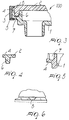
- the method for manufacturing the intake muffler according to the present invention comprises a first step which consists in molding the base 1 and the cover 2 of the muffler in separate molds, thus obtaining the finished parts meant to be assembled in order to constitute the intake muffler, generally designated by the reference numeral 100 in Figure 3.
- the step for the assembly of the muffler is performed in a suitable assembly mold, in which a perimetric profile is formed, being adapted to provide a retention joint 3 which is molded perimetrically at the coupling edge of the base 1 and of the cover 2.
- the retention joint 3 thus closes the perimeter of the base and of the cover of the muffler; in order to provide a hermetic coupling on the upper surface of the cover 2, at the edge, and on the lower surface of the base, at the rim, perimetric grooves 4 are provided in which complementarily shaped raised portions 5 engage.
- the raised portions are formed on the retention joint 3 as a consequence of molding in the mold for the assembly of the muffler 100.
- the retention joint therefore has, in a transverse sectional view, a substantially C-shaped profile as shown in Figure 3.
- the coupling between the base 1 and the cover 2 occurs by means of the interlocking of a frustum-shaped protrusion 6 of the cover 2 in a cavity 7 formed in the base 1.
- the frustum-like shape of the cavity 7 and of the protrusion 6 allows to obtain an interlock between the base 1 and the cover 2 which combines with the action of the retention joint 3, engaging between the rim of the cover 2 and the rim of the base 1, as described above.
- the molding of the retention joint 3 around the seam for coupling the base and the cover eliminates the possibility of forming internal flash and any external flash that might form at the closure regions of the mold can be easily eliminated.
- the compactness of the muffler can be increased by using additional systems for mutually anchoring the retention joint 3 and the base 1 of the muffler.
- undercuts 8 formed as grooves provided in the outer rim of the base 1 of the muffler.
- the method according to the invention fully achieves the intended aim, since it allows to perform the hermetic assembly of an intake muffler while avoiding the forming of internal and external perimetric flash, which can be damaging, if it breaks off, by obstructing capillary passages in which the cooling air aspirated by the compressor through said muffler must pass.
- the base 1 and the cover 2 of the muffler can be provided, at one or more outer rim regions, with an undercut which is more definite than the undercuts 4 (perimetric grooves) shown in Figure 3, to anchor the retention jont 3.
- the outer rim profile is suitably interrupted at one or more regions, to define at least one indentation 10. Accordingly, the retention joint 3 is molded perimetrically and the indentation 10 fills with molded material when the base and the cover are assembled, in order to strenghten the coupling.
- the materials employed may be any according to requirements and to the state of the art.
Landscapes
- Engineering & Computer Science (AREA)
- Mechanical Engineering (AREA)
- General Engineering & Computer Science (AREA)
- Compressor (AREA)
- Exhaust Silencers (AREA)
- Transmission Systems Not Characterized By The Medium Used For Transmission (AREA)
- Tone Control, Compression And Expansion, Limiting Amplitude (AREA)
Applications Claiming Priority (2)
| Application Number | Priority Date | Filing Date | Title |
|---|---|---|---|
| ITMI972073 | 1997-09-11 | ||
| ITMI972073 IT1295020B1 (it) | 1997-09-11 | 1997-09-11 | Procedimento di realizzazione di muffola di aspirazione, particolarmente per circuiti di compressione per impianti frigoriferi |
Publications (3)
| Publication Number | Publication Date |
|---|---|
| EP0902184A2 true EP0902184A2 (fr) | 1999-03-17 |
| EP0902184A3 EP0902184A3 (fr) | 2000-03-22 |
| EP0902184B1 EP0902184B1 (fr) | 2005-04-20 |
Family
ID=11377859
Family Applications (1)
| Application Number | Title | Priority Date | Filing Date |
|---|---|---|---|
| EP19980115986 Expired - Lifetime EP0902184B1 (fr) | 1997-09-11 | 1998-08-25 | Procédé de production d'un amortisseur de son pour une ouverture d'admission de fluide partculièrement adapté pour des circuits de compression des installations de réfrigération |
Country Status (4)
| Country | Link |
|---|---|
| EP (1) | EP0902184B1 (fr) |
| DE (1) | DE69829810T2 (fr) |
| ES (1) | ES2242252T3 (fr) |
| IT (1) | IT1295020B1 (fr) |
Cited By (4)
| Publication number | Priority date | Publication date | Assignee | Title |
|---|---|---|---|---|
| WO2000073656A1 (fr) * | 1999-05-27 | 2000-12-07 | Matsushita Refrigeration Company | Silencieux d'aspiration pour compresseur hermetique |
| EP1316943A3 (fr) * | 2001-11-28 | 2003-12-17 | Omron Corporation | Filtre acoustique |
| EP1088993A4 (fr) * | 1999-04-15 | 2004-08-04 | Matsushita Refrigeration | Silencieux d'aspiration et compresseur electrique ferme |
| WO2004085848A1 (fr) * | 2003-03-28 | 2004-10-07 | Empresa Brasileira De Compressores S.A. - Embraco | Silencieux d'aspiration pour compresseur hermetique |
Family Cites Families (6)
| Publication number | Priority date | Publication date | Assignee | Title |
|---|---|---|---|---|
| FR1005684A (fr) * | 1947-09-05 | 1952-04-15 | Roulements A Aiguilles Sa | Procédé d'assemblage d'éléments métalliques et assemblages résultant de l'application de ce procédé |
| JPS5943917A (ja) * | 1982-09-02 | 1984-03-12 | Sanyo Electric Co Ltd | 圧縮機の吸込マフラ製造方法 |
| DE3312231A1 (de) * | 1983-04-05 | 1984-10-11 | Bayer Ag, 5090 Leverkusen | Hohlkoerper aus kunststoffen |
| BR8804016A (pt) * | 1988-07-29 | 1990-03-20 | Brasil Compressores Sa | Aperfeicoamento em sistema de succao para compressor hermetico de refrigeracao |
| FR2690376B1 (fr) * | 1992-04-22 | 1995-08-11 | Aplast Consortium | Procede pour fabriquer un corps creux en matiere plastique par assemblage de deux demi-coquilles, et corps creux ainsi obtenu, notamment collecteur d'amission d'air de moteur a explosion. |
| US5341654A (en) * | 1993-04-16 | 1994-08-30 | Copeland Corporation | Suction gas conduit |
-
1997
- 1997-09-11 IT ITMI972073 patent/IT1295020B1/it active IP Right Grant
-
1998
- 1998-08-25 EP EP19980115986 patent/EP0902184B1/fr not_active Expired - Lifetime
- 1998-08-25 DE DE69829810T patent/DE69829810T2/de not_active Expired - Fee Related
- 1998-08-25 ES ES98115986T patent/ES2242252T3/es not_active Expired - Lifetime
Cited By (9)
| Publication number | Priority date | Publication date | Assignee | Title |
|---|---|---|---|---|
| EP1088993A4 (fr) * | 1999-04-15 | 2004-08-04 | Matsushita Refrigeration | Silencieux d'aspiration et compresseur electrique ferme |
| WO2000073656A1 (fr) * | 1999-05-27 | 2000-12-07 | Matsushita Refrigeration Company | Silencieux d'aspiration pour compresseur hermetique |
| AU754210B2 (en) * | 1999-05-27 | 2002-11-07 | Matsushita Refrigeration Company | Suction muffler for a hermetic compressor |
| US6688856B1 (en) | 1999-05-27 | 2004-02-10 | Matsushita Refrigeration Company | Suction muffler for a hermetic compressor |
| EP1316943A3 (fr) * | 2001-11-28 | 2003-12-17 | Omron Corporation | Filtre acoustique |
| WO2004085848A1 (fr) * | 2003-03-28 | 2004-10-07 | Empresa Brasileira De Compressores S.A. - Embraco | Silencieux d'aspiration pour compresseur hermetique |
| CN100414101C (zh) * | 2003-03-28 | 2008-08-27 | 巴西船用压缩机有限公司 | 用来关闭封闭式压缩机的吸入消声器的系统 |
| US7500540B2 (en) | 2003-03-28 | 2009-03-10 | Empresa Brasileira De Compressores S.A. Embraco | Suction muffler for a hermetic compressor |
| KR101039365B1 (ko) * | 2003-03-28 | 2011-06-08 | 월풀 에쎄.아. | 밀폐형 압축기의 흡입 머플러 |
Also Published As
| Publication number | Publication date |
|---|---|
| IT1295020B1 (it) | 1999-04-27 |
| EP0902184A3 (fr) | 2000-03-22 |
| ES2242252T3 (es) | 2005-11-01 |
| DE69829810T2 (de) | 2006-03-02 |
| ITMI972073A1 (it) | 1999-03-11 |
| DE69829810D1 (de) | 2005-05-25 |
| EP0902184B1 (fr) | 2005-04-20 |
Similar Documents
| Publication | Publication Date | Title |
|---|---|---|
| US8833771B2 (en) | Gasket assembly with improved locating and retention pin and method of construction thereof | |
| CA1279579C (fr) | Dispositif pour amortir un bruit d'aspiration | |
| JPH06191280A (ja) | 開閉可能な車輛ルーフのカバーおよびそのカバーの製造方法 | |
| EP0902184B1 (fr) | Procédé de production d'un amortisseur de son pour une ouverture d'admission de fluide partculièrement adapté pour des circuits de compression des installations de réfrigération | |
| US6394226B1 (en) | Method for manufacturing an intake muffler particularly for compression circuit for refrigeration systems and the like | |
| EP1415101B1 (fr) | Dispositif comprenant un joint d'etancheite place entre deux elements constitutifs | |
| JP2004502480A (ja) | 接合されるテープに溶着された歯を備える封止用スライドファスナ | |
| GB2271955A (en) | Joining the ends of a weatherstrip by moulding | |
| CA2182712A1 (fr) | Joint en elastomere, particulierement pour portes de four de cuisson | |
| JPH0345212B2 (fr) | ||
| US20070262537A1 (en) | Method for the Production of a Flat Seal, and Flat Seal | |
| JP2001280207A (ja) | 仕切板付きタンク | |
| US20080296218A1 (en) | Oil Canning of Mesh Screen for Filter | |
| CA2626478C (fr) | Silencieux acoustique pour compresseur hermetique | |
| KR100349703B1 (ko) | 차량용 등기구 및 그 제조 방법 | |
| CN220135314U (zh) | 一种灯具及灯具的壳体 | |
| KR200156186Y1 (ko) | 밀폐형 압축기의 머플러 | |
| JPH10141508A (ja) | バックアップリング付きオイルシール | |
| JP2003025418A (ja) | ブロー成形用型内インサート | |
| JP3255851B2 (ja) | 密閉型電動圧縮機 | |
| JPH0694165A (ja) | ウォールカバー | |
| KR100517173B1 (ko) | 타이어 가류금형의 블레이드 구조_ | |
| JPH0986175A (ja) | ウエザーストリップの接続構造 | |
| JPH05288117A (ja) | ガスケット | |
| JP4484000B2 (ja) | リップシールの製造方法 |
Legal Events
| Date | Code | Title | Description |
|---|---|---|---|
| PUAI | Public reference made under article 153(3) epc to a published international application that has entered the european phase |
Free format text: ORIGINAL CODE: 0009012 |
|
| AK | Designated contracting states |
Kind code of ref document: A2 Designated state(s): DE ES FR GB IT |
|
| AX | Request for extension of the european patent |
Free format text: AL;LT;LV;MK;RO;SI |
|
| PUAL | Search report despatched |
Free format text: ORIGINAL CODE: 0009013 |
|
| AK | Designated contracting states |
Kind code of ref document: A3 Designated state(s): AT BE CH CY DE DK ES FI FR GB GR IE IT LI LU MC NL PT SE |
|
| AX | Request for extension of the european patent |
Free format text: AL;LT;LV;MK;RO;SI |
|
| RIC1 | Information provided on ipc code assigned before grant |
Free format text: 7F 04B 39/00 A, 7B 29C 67/00 B |
|
| 17P | Request for examination filed |
Effective date: 20000825 |
|
| AKX | Designation fees paid |
Free format text: DE ES FR GB IT |
|
| 17Q | First examination report despatched |
Effective date: 20040107 |
|
| GRAP | Despatch of communication of intention to grant a patent |
Free format text: ORIGINAL CODE: EPIDOSNIGR1 |
|
| GRAS | Grant fee paid |
Free format text: ORIGINAL CODE: EPIDOSNIGR3 |
|
| GRAA | (expected) grant |
Free format text: ORIGINAL CODE: 0009210 |
|
| AK | Designated contracting states |
Kind code of ref document: B1 Designated state(s): DE ES FR GB IT |
|
| REG | Reference to a national code |
Ref country code: GB Ref legal event code: FG4D |
|
| REF | Corresponds to: |
Ref document number: 69829810 Country of ref document: DE Date of ref document: 20050525 Kind code of ref document: P |
|
| PG25 | Lapsed in a contracting state [announced via postgrant information from national office to epo] |
Ref country code: GB Free format text: LAPSE BECAUSE OF NON-PAYMENT OF DUE FEES Effective date: 20050825 |
|
| REG | Reference to a national code |
Ref country code: ES Ref legal event code: FG2A Ref document number: 2242252 Country of ref document: ES Kind code of ref document: T3 |
|
| PLBE | No opposition filed within time limit |
Free format text: ORIGINAL CODE: 0009261 |
|
| STAA | Information on the status of an ep patent application or granted ep patent |
Free format text: STATUS: NO OPPOSITION FILED WITHIN TIME LIMIT |
|
| 26N | No opposition filed |
Effective date: 20060123 |
|
| GBPC | Gb: european patent ceased through non-payment of renewal fee |
Effective date: 20050825 |
|
| EN | Fr: translation not filed | ||
| PGFP | Annual fee paid to national office [announced via postgrant information from national office to epo] |
Ref country code: ES Payment date: 20080228 Year of fee payment: 10 |
|
| PGFP | Annual fee paid to national office [announced via postgrant information from national office to epo] |
Ref country code: IT Payment date: 20080228 Year of fee payment: 10 Ref country code: DE Payment date: 20080228 Year of fee payment: 10 |
|
| PG25 | Lapsed in a contracting state [announced via postgrant information from national office to epo] |
Ref country code: FR Free format text: LAPSE BECAUSE OF NON-PAYMENT OF DUE FEES Effective date: 20050831 |
|
| PG25 | Lapsed in a contracting state [announced via postgrant information from national office to epo] |
Ref country code: FR Free format text: LAPSE BECAUSE OF NON-PAYMENT OF DUE FEES Effective date: 20050420 |
|
| PG25 | Lapsed in a contracting state [announced via postgrant information from national office to epo] |
Ref country code: IT Free format text: LAPSE BECAUSE OF NON-PAYMENT OF DUE FEES Effective date: 20080825 Ref country code: DE Free format text: LAPSE BECAUSE OF NON-PAYMENT OF DUE FEES Effective date: 20090303 |
|
| REG | Reference to a national code |
Ref country code: ES Ref legal event code: FD2A Effective date: 20080826 |
|
| PG25 | Lapsed in a contracting state [announced via postgrant information from national office to epo] |
Ref country code: ES Free format text: LAPSE BECAUSE OF NON-PAYMENT OF DUE FEES Effective date: 20080826 |