EP0902597A1 - System zur Verkehrsbeobachtung - Google Patents
System zur Verkehrsbeobachtung Download PDFInfo
- Publication number
- EP0902597A1 EP0902597A1 EP98402240A EP98402240A EP0902597A1 EP 0902597 A1 EP0902597 A1 EP 0902597A1 EP 98402240 A EP98402240 A EP 98402240A EP 98402240 A EP98402240 A EP 98402240A EP 0902597 A1 EP0902597 A1 EP 0902597A1
- Authority
- EP
- European Patent Office
- Prior art keywords
- analyzer
- outputs
- switching
- mic
- network
- Prior art date
- Legal status (The legal status is an assumption and is not a legal conclusion. Google has not performed a legal analysis and makes no representation as to the accuracy of the status listed.)
- Granted
Links
Images



Classifications
-
- H—ELECTRICITY
- H04—ELECTRIC COMMUNICATION TECHNIQUE
- H04W—WIRELESS COMMUNICATION NETWORKS
- H04W24/00—Supervisory, monitoring or testing arrangements
Definitions
- the present invention relates to a system network traffic observation mobile radio such as the GSM system (Global System for Mobile).
- GSM system Global System for Mobile
- the B.S.S. distributes the radio network. It is made up of base stations (B.T.S. Base Transceiver Station) managed by a base station controller (B.S.C. Base Station Controller).
- a B.T.S. base station is the ensuring element the interface between the terrestrial network and mobiles.
- each B.T.S. is defined by the radio coverage requirement for a specific area.
- base B.T.S. In low density areas the base B.T.S. cover an emission radius and strong reception, while in high density areas B.T.S. base stations are more numerous and cover smaller areas.
- a B.S.C. manages base stations B.T.S. attached to it. He realizes the procedures for establishing radio calls and release, as well as the procedures for maintaining communications (power control, handover).
- the B.S.C. further provides a function of concentration of the transmission links which are M.I.C. (Pulse modulation and Coding) by allowing the channels of base station traffic on a number restricted channels to its switch attachment (M.S.C.).
- M.I.C. Pulse modulation and Coding
- B.S.C. are placed so that reduce their number and the distance of the M.I.C. use.
- the N.S.S. subsystem consists of a switches (M.S.C. Mobile Services Switching Center) as well as nominal location recorders (H.L.R.) and temporary (V.I.R.).
- the mobile switching center M.S.C. ensure the transport of communications between fixed subscribers and mobile. It is a digital switch capable perform all the functions necessary for the call management of mobile subscribers located in its area.
- V.L.R. Visited Location Register Visited Location Register
- H.L.R. Home Location Register nominal M.S.C.
- the location of the mobile switching center M.S.C./V.L.R. is done so as to reduce its distance compared to the B.S.S.
- the V.L.R. stores data necessary for calls locally incoming and outgoing mobile subscribers who are registered in its database.
- the subscribers mobile are those found in areas of locations managed by the V.L.R.
- the radio interface ensures communication between the mobile and the B.T.S. for the transmission of digital signals. It is based on the LAPDm protocol.
- the A Bis interface is structured to transport user traffic (voice and data) as well as the signage between the B.S.C. and the B.T.S.
- Physical access between the B.T.S. and the B.S.C. is made by digital M.I.C. 2048 Kbit / s architectured in 32 64 Kbit / s time intervals. Each time interval corresponds to a channel of traffic used on the radio interface.
- Interface A provides traffic transport for users (voice and data) and signaling between B.S.S. and N.S.S.
- Transporting user traffic requires allocation of land resources between the B.S.S. and the N.S.S.These land resources are circuits identified by a time interval number and an M.I.C.
- the mobile station During call establishment, the mobile station practice a first access on the cell channel. In response to this the B.S.C. allocate to the station a first dedicated channel. After pick up by the station mobile of this radio channel, a path exists between this one and the B.S.C. The mobile station then uses this path to send an initial message.
- the B.S.C. Upon receipt of the initial message, the B.S.C. establishes with the M.S.C. on the interface has a connection dedicated to this mobile station. These two elements, one on the radio interface the other on interface A constitute a dedicated path from the mobile station M.S.C. The dialogue can then proceed.
- a physical interface A has several MIC connections (N connections, this number not being always the same depending on the interfaces).
- a first disadvantage of this system is that a connection sometimes generated disturbances on M.I.C correspondents resulting in cuts communications.
- a second disadvantage of this system is that it requires manual connection to be implemented on place on the site, in practice 20 connections for four MICs to test.
- this implementation requires a movement in the switching center (M.S.C.) generally located tens of kilometers from the place of observation, that is to say of the place where is located the traffic observation piloting equipment.
- M.S.C. switching center
- the present invention makes it possible to remedy these problems and proposes for that to connect between the analyzer and the MIC links an interface of automatic switching to route an output of the analyzer to any of the MIC links to observe.
- the interface is remotely controllable thanks to an ISDN link connecting a control unit to the protocol analyzer. Thanks to this connection the protocol analyzer is as transferred to the place of order.
- the command parameters are transmitted by the analyzer to the switch box and the box switches between its different outputs and the MIC channels to be observed according to the instructions it received from the analyzer.
- the present invention more particularly has for object a traffic observation system of a network of mobile radiocommunication comprising per site, one switching center connected to controllers base station by N transmission links digital (MIC) and / or a base station controller connected to base stations by N links digital transmission (MIC); at least one protocol with n outputs, mainly in this that it further comprises switching means with n inputs and N outputs, suitable for routing the signals of each input on one of the outputs, the n inputs corresponding to the n outputs of the analyzer and the N outputs being connected to the N MIC connections to be observed.
- MIC transmission links digital
- MIC transmission links digital
- the system comprises a steering body for the protocol analyzer connected to the analyzer by a transmission line digital to remotely control the progress of network analysis and management of resources switching.
- the line is a line of the network to service integration (ISDN).
- ISDN network to service integration
- the means of switching have a formed switching assembly of flip-flops and relays and a unit of control capable of actuating the switching relays.
- the means of switching can be turned on or off without interruption of telephone communications.
- Another object of the present invention relates to a switching device for observation system traffic with at least one protocol analyzer (AP) with n outputs and intended to analyze N bonds of digital transmission (MIC), said device comprising for this at least n likely inputs to be connected to the n outputs of an analyzer and to the minus N outputs likely to be connected to N digital transmission links (MIC), and being able to direct each entry to one of the exits.
- AP protocol analyzer
- MIC digital transmission links
- the device for switching includes a switching set comprising a set of flip-flops per outlet of the relay analyzer so that a relay either placed at each exit of each scale and a control unit capable of actuating the relay switching.
- the switching device can be connected to the traffic monitoring system without interruption of telephone communications.
- the device for switching is in the form of a box independent of the protocol analyzer connectable to outputs of the analyzer and to the MIC connections to be observed.
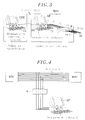
- the system proposed and shown schematically in Figure 3 consists in connecting an AP protocol analyzer (or tester) in each site of the network.
- a site can be monosectoral, i.e. each cell is covered by a base station, or trisectorial this which means that a base station covers three cells.
- the switching means can be realized by a device in the form of a card internal electronics to the protocol analyzer which then includes the number of outputs corresponding to number of MIC channels to analyze.
- the switching means are made by a box independent of the analyzer protocol connectable to the outputs of the analyzer and MIC connections to observe.
- This switch box can be used on the A or A-Bis interface. On interface A it will be inserted between the mobile switching center M.S.C and the base station controller B.S.C. On the interface A-Bis it will be inserted between the station controller B.S.C base and B.T.S.
- the CDE piloting unit of the AP analyzer can be placed in a radiotelephone and will be connected to the AP analyzer by a transmission link L of the telephone network switched.
- This link L could for example be a network digital transmission link to ISDN service integration.
- a port PS series of the AP analyzer is connected by a link LS series or B case to ensure the transfer of configuration parameters between the AP analyzer and the housing B.
- the CDE control unit performs the function of remote control for the box through the AP analyzer and for said analyzer. It is made up of a unit central type P.C. connected to a connection box to the ISDN network (not shown) and responsible for a program remote control of the analyzer.
- This program enables communication with the analyzer at the request of a user. Once the communication established, the user can then return configuration parameters of the switching to the CDE unit just as if it did directly on the analyzer. The AP analyzer screen is reflected on the control unit.
- the remote control program executed by the CDE control unit is able to allow the control of the application executed by the AP protocol and this by keystroke CL keyboard and mouse clicks of this unit CDE control unit and by means of the display on its screen of images that are on the remote screen (analyzer screen).
- Interface A just like the A-Bis interface according to GSM standard, has a variable number N of links MIC. Observing a MIC requires connecting 2 wires for transmission, 2 wires for reception and 1 wire massive.
- Another advantage of the present invention is that it becomes quite possible to connect two or more protocol analyzers on interface A or A-Bis, it will be necessary in this case to provide for the housing a number of entries equal to n times the number of analyzers.
- this switch box is transparent with respect to the analyzer. It simply allows a ports of the analyzer.
- the impedance of the latter is infinite.
- GSM protocols decodable by the K1103 analyzer are based on a protocol stacking mechanism. Some protocols differ depending on the interface (A or A bis) that we want to observe. Interface A provides mainly network management while the A-Bis interface concerns that of the mobile.
- the AP protocol analyzer allows in particular to monitor and analyze signaling errors GSM digital telephone network on interface A and A-Bis. It analyzes the signaling in both direction of transmission which is made up of a pair send and receive pair.
- the AP protocol analyzer allows the observation of a maximum of four MIC links between two points on the network, for example between the station controller B.S.C. and the M.S.C.
- FIG. 4 illustrates this application.
- the flow of the bipolar signals observed is 2048 Kbit / s. These 6-volt peak-to-peak amplitude signals corresponding to an HDB3 type coding.
- This box has a control unit 10 which is carried out according to the application example given by a microcontroller such as the microcontroller referenced MC68HC11 using HCMOS technology, which has advantage of combining a small size with a bus fast 2MHz and low power consumption.
- a microcontroller such as the microcontroller referenced MC68HC11 using HCMOS technology, which has advantage of combining a small size with a bus fast 2MHz and low power consumption.
- the memory chip contains 8 kbytes of non-memory volatile.
- This is program memory 20 (ROM) of the microcontroller and it contains a program capable activate the appropriate toggles (as detailed below) according to the parameters of configuration received by the microcontroller.
- This chip memory further includes 512 bytes of memory from electrically programmable and electrically programmable erasable 30 (EEPROM) to allow updates of the ROM program and 256 bytes of working memory 40.
- EEPROM electrically programmable and electrically programmable erasable 30
- the housing further includes a set of switching comprising of relay switches 50 and bistable scales 60.
- Each of the n inputs of box B is able to be switched to one of the N outputs, and for this nxN relay are used, i.e. 4x24 in the example implementation given previously.
- a serial clock of one mega Hertz synchronizes the input of data on the rising edge in the scales.
- Each input E1-E4 uses 3 flip-flops, i.e. 24 bits required to code each of the 24 outputs S1 to S24.
- the relays are such no input and output are connected.
- the pilot program implemented on the AP analyzer asks the user for the number of the M.I.C. that he wants observe on each of the four inputs E1-E4.
- the program transforms the number received in the form of 3 digits (3 bytes) which it sends one after the other on the LS serial link. The transmission is secure. AT this end, as soon as the first byte is received by the microcontroller 10 of the housing B, the latter returns it to the AP analyzer. Once the 3 bytes have been sent and received, the AP analyzer compares the sum of the bytes sent to the sum of the bytes received. If these sums are different, the control program of the box asks the user for the M.I.C. number again
- the corresponding relays R1 to RN, or RN + 1 to R2N, or ... R3N + 1 to R4N commute.
- the desired connections between the inputs and the outputs are established.
- the user can then configure the protocol analyzer and observe the network traffic.
- the switch box performs a reset automatically after 2 minutes.
- the housing does will not connect outputs to the inputs.
- the relays used are bistable relays with changeover contacts composed of two coils installed on a magnetic circuit (electromagnet) and several change-over contacts (opening and closing closure with a common point).
- This set provides switching instant upon taking the line which makes the even more transparent observation system of the application versus the state system of the technical.
- CB1-CB24 patch cords are provided to each contain the wires of a MIC link. These cords are further equipped with M1-M24 connectors to one end intended to be connected to the fixed mounting F and at the other end of C1-C24 connectors which can be connected indifferently to outputs S1-S24 of the box switch B or at the outputs of the AP analyzer.
Landscapes
- Engineering & Computer Science (AREA)
- Computer Networks & Wireless Communication (AREA)
- Signal Processing (AREA)
- Mobile Radio Communication Systems (AREA)
- Data Exchanges In Wide-Area Networks (AREA)
Applications Claiming Priority (2)
| Application Number | Priority Date | Filing Date | Title |
|---|---|---|---|
| FR9711409 | 1997-09-12 | ||
| FR9711409A FR2768583B1 (fr) | 1997-09-12 | 1997-09-12 | Systeme d'observation du trafic |
Publications (2)
| Publication Number | Publication Date |
|---|---|
| EP0902597A1 true EP0902597A1 (de) | 1999-03-17 |
| EP0902597B1 EP0902597B1 (de) | 2001-06-13 |
Family
ID=9511055
Family Applications (1)
| Application Number | Title | Priority Date | Filing Date |
|---|---|---|---|
| EP98402240A Expired - Lifetime EP0902597B1 (de) | 1997-09-12 | 1998-09-10 | System zur Verkehrsbeobachtung |
Country Status (4)
| Country | Link |
|---|---|
| US (1) | US6438372B1 (de) |
| EP (1) | EP0902597B1 (de) |
| DE (1) | DE69800916T2 (de) |
| FR (1) | FR2768583B1 (de) |
Cited By (2)
| Publication number | Priority date | Publication date | Assignee | Title |
|---|---|---|---|---|
| WO2002011478A1 (en) * | 2000-08-01 | 2002-02-07 | Simtel S.R.L. | System for monitoring the performance of mobile telephony networks |
| RU2239294C2 (ru) * | 2000-03-02 | 2004-10-27 | Открытое акционерное общество "Московская телекоммуникационная корпорация" | Устройство для дистанционного выборочного контроля каналов связи в многоканальной сети связи |
Families Citing this family (1)
| Publication number | Priority date | Publication date | Assignee | Title |
|---|---|---|---|---|
| DE10035483B4 (de) * | 2000-07-21 | 2005-07-21 | Sartorius Hamburg Gmbh | Kraftaufnehmer für einen Fahrzeugsitz |
Citations (5)
| Publication number | Priority date | Publication date | Assignee | Title |
|---|---|---|---|---|
| US4860281A (en) * | 1988-02-29 | 1989-08-22 | Motorola, Inc. | Individual subchannel loopback in the PCM interfaces of a digital telephone exchange with control of the outbound path |
| DE4205239A1 (de) * | 1992-02-21 | 1993-08-26 | Sel Alcatel Ag | Mobiles testgeraet fuer ein mobilfunk-system |
| EP0710043A1 (de) * | 1994-10-28 | 1996-05-01 | Hewlett-Packard Company | Überwachungsverfahren für ein zellulares Mobilfunksystem zur Gewinnung von Gebietsinformation |
| EP0738091A1 (de) * | 1995-04-11 | 1996-10-16 | Hewlett-Packard Company | Erkennungsverfahren zur Bestimmung von Information über ein Signalisierungsnetz |
| FR2753596A1 (fr) * | 1996-09-17 | 1998-03-20 | Cegetel Etudes Et Gestion | Systeme et procede de controle d'un reseau de radiocommunication cellulaire au moyen d'un ensemble d'analyseurs de protocole et de stations mobiles |
Family Cites Families (10)
| Publication number | Priority date | Publication date | Assignee | Title |
|---|---|---|---|---|
| US4424421A (en) * | 1981-10-23 | 1984-01-03 | Lynch Communication Systems, Inc. | Apparatus for testing subscriber carrier systems |
| JP2726315B2 (ja) * | 1989-09-20 | 1998-03-11 | 富士通株式会社 | 移動通信システムの回線異常検出方法 |
| US5287506A (en) * | 1991-10-17 | 1994-02-15 | Hewlett-Packard Company | Token ring network protocol analyzer |
| US5373501A (en) * | 1992-07-10 | 1994-12-13 | C & P Of Virginia | Telecommunications switching network including improved port selector and control circuitry |
| US5375159A (en) * | 1992-09-29 | 1994-12-20 | C & P Of Virginia | System and method for remote testing and protocol analysis of communication lines |
| US5457729A (en) * | 1993-03-15 | 1995-10-10 | Symmetricom, Inc. | Communication network signalling system link monitor and test unit |
| NO940977L (no) * | 1993-04-06 | 1994-10-05 | Alcatel Str Ag | Fremgangsmåte og anordning for å sikre tjenestekvaliteten i et mobilt radiosystem |
| NO942031L (no) * | 1994-06-01 | 1995-12-04 | Ericsson As Creative Engineeri | System for overvåkning av telefonnett og/eller datakommunikasjonsnett, spesielt mobiltelefonnett |
| JPH08293828A (ja) * | 1995-04-21 | 1996-11-05 | Nec Corp | 携帯無線通信システムにおけるセルサイト試験方式 |
| KR100206463B1 (ko) * | 1995-12-30 | 1999-07-01 | 윤종용 | 이동체 통신장치의 무선특성 평가 장치 |
-
1997
- 1997-09-12 FR FR9711409A patent/FR2768583B1/fr not_active Expired - Fee Related
-
1998
- 1998-09-09 US US09/150,627 patent/US6438372B1/en not_active Expired - Fee Related
- 1998-09-10 EP EP98402240A patent/EP0902597B1/de not_active Expired - Lifetime
- 1998-09-10 DE DE69800916T patent/DE69800916T2/de not_active Expired - Lifetime
Patent Citations (5)
| Publication number | Priority date | Publication date | Assignee | Title |
|---|---|---|---|---|
| US4860281A (en) * | 1988-02-29 | 1989-08-22 | Motorola, Inc. | Individual subchannel loopback in the PCM interfaces of a digital telephone exchange with control of the outbound path |
| DE4205239A1 (de) * | 1992-02-21 | 1993-08-26 | Sel Alcatel Ag | Mobiles testgeraet fuer ein mobilfunk-system |
| EP0710043A1 (de) * | 1994-10-28 | 1996-05-01 | Hewlett-Packard Company | Überwachungsverfahren für ein zellulares Mobilfunksystem zur Gewinnung von Gebietsinformation |
| EP0738091A1 (de) * | 1995-04-11 | 1996-10-16 | Hewlett-Packard Company | Erkennungsverfahren zur Bestimmung von Information über ein Signalisierungsnetz |
| FR2753596A1 (fr) * | 1996-09-17 | 1998-03-20 | Cegetel Etudes Et Gestion | Systeme et procede de controle d'un reseau de radiocommunication cellulaire au moyen d'un ensemble d'analyseurs de protocole et de stations mobiles |
Non-Patent Citations (1)
| Title |
|---|
| H LUTHI: "QVoice - die neue Generation von Diagnose-Systemen für zellulare Mobilfunk-Netze", DAS TECHNISCHE MAGAZIN VON ASCOM, no. 3, 1 March 1995 (1995-03-01), BERN,CH, pages 30 - 4, XP000557527 * |
Cited By (3)
| Publication number | Priority date | Publication date | Assignee | Title |
|---|---|---|---|---|
| RU2239294C2 (ru) * | 2000-03-02 | 2004-10-27 | Открытое акционерное общество "Московская телекоммуникационная корпорация" | Устройство для дистанционного выборочного контроля каналов связи в многоканальной сети связи |
| WO2002011478A1 (en) * | 2000-08-01 | 2002-02-07 | Simtel S.R.L. | System for monitoring the performance of mobile telephony networks |
| US7069004B2 (en) | 2000-08-01 | 2006-06-27 | Commprove, Ltd. | System for monitoring the performance of mobile telephony networks |
Also Published As
| Publication number | Publication date |
|---|---|
| DE69800916D1 (de) | 2001-07-19 |
| US6438372B1 (en) | 2002-08-20 |
| FR2768583A1 (fr) | 1999-03-19 |
| FR2768583B1 (fr) | 2000-06-23 |
| DE69800916T2 (de) | 2001-10-18 |
| EP0902597B1 (de) | 2001-06-13 |
Similar Documents
| Publication | Publication Date | Title |
|---|---|---|
| EP0460486B1 (de) | Verfahren zur zentralen Wartung für ein schnurloses Telefonnetzwerk | |
| FR2703538A1 (fr) | Station d'un réseau de radiocommunication numérique à moyens d'échange de signaux de parole et moyens d'échange de signaux de données. | |
| CA2333958A1 (en) | Method and apparatus for providing global communications interoperability | |
| EP0015524A1 (de) | Automatisches Vermittlungssystem mit digitalem Koppelfeld | |
| FR2677833A1 (fr) | Installation de telesurveillance a balayage lent utilisant le systeme de communication radio mobile. | |
| EP0932315B1 (de) | Vorrichtung zur Erkennung eines gerufenen Endgeräts aus mehreren Teilnehmerendgeräten einer Fernsprechvermittlung, wobei die Fernsprechvermittlung mit mindestens einem festen Funkfernsprechendgerät verbunden ist | |
| EP0902597B1 (de) | System zur Verkehrsbeobachtung | |
| FR3030992A1 (fr) | Systeme et procede de transmission de donnees utilisant conjointement une liaison terrestre et une liaison satellitaire | |
| EP0367007B1 (de) | Vermittlungszentrale für den Einsatz im Mobilfunk | |
| EP0956682B1 (de) | Vorrichtung zur allgemeinen leitweglenkung von nachrichten in verschiedenen formaten und unterschiendlichen protokollen | |
| CA2132594C (fr) | Systeme de transmission de donnees par satellite entre centres de commutation telephoniques, station de trafic et procede de transmission correspondants | |
| CA2089847C (fr) | Systeme de gestion dynamique d'un ensemble d'equipements relies en reseau de telecommunications | |
| US20020009093A1 (en) | Method for communicating signaling messages through a broadband network | |
| CA1215483A (fr) | Dispositif de transfert et de traitement de voies de donnees ou de signalisation d'un ensemble de lignes multiplex | |
| US7398085B2 (en) | Telecommunications and telephony network | |
| CA2370526A1 (fr) | Systeme de mise en oeuvre de services telephoniques, organe de commande d'un autocommutateur et serveur cti | |
| FR2698748A1 (fr) | Réseau hertzien et procédé pour transmettre des services supplémentaires dans ce réseau. | |
| EP0831668A1 (de) | Selbstanpassendes Protokoll zwischen Basisstationen eines zellularen Telefonnetzwerkes | |
| RU2004135535A (ru) | Способ и устройство для передачи информации | |
| EP1095485B1 (de) | Mobiles netzwerksystem zum zeitweisen verbinden mit einem festen informationssystem | |
| CN1321372A (zh) | Leo卫星数据传输设备 | |
| EP0569645A1 (de) | Verfahren und Einrichtung für telefonische Verbindungen mit ununterbrochener Dienstleistung in einem Netzwerk von selbstständigen Stationen | |
| EP0854593B1 (de) | Verfahren zur Frequenzsteuerung von einem Zwischenverstärker in einem Übetragungssystem | |
| EP0790748A1 (de) | Signalisierungsverwaltungsverfahren in Vermittlungssystem mit Funk-Feststationen | |
| FR2528646A1 (fr) | Dispositif de transmission entre les terminaisons d'un systeme de communication temporel |
Legal Events
| Date | Code | Title | Description |
|---|---|---|---|
| PUAI | Public reference made under article 153(3) epc to a published international application that has entered the european phase |
Free format text: ORIGINAL CODE: 0009012 |
|
| AK | Designated contracting states |
Kind code of ref document: A1 Designated state(s): DE FR GB IT SE |
|
| AX | Request for extension of the european patent |
Free format text: AL;LT;LV;MK;RO;SI |
|
| 17P | Request for examination filed |
Effective date: 19990520 |
|
| AKX | Designation fees paid |
Free format text: DE FR GB IT SE |
|
| 17Q | First examination report despatched |
Effective date: 19991230 |
|
| GRAG | Despatch of communication of intention to grant |
Free format text: ORIGINAL CODE: EPIDOS AGRA |
|
| GRAG | Despatch of communication of intention to grant |
Free format text: ORIGINAL CODE: EPIDOS AGRA |
|
| GRAH | Despatch of communication of intention to grant a patent |
Free format text: ORIGINAL CODE: EPIDOS IGRA |
|
| GRAH | Despatch of communication of intention to grant a patent |
Free format text: ORIGINAL CODE: EPIDOS IGRA |
|
| GRAA | (expected) grant |
Free format text: ORIGINAL CODE: 0009210 |
|
| AK | Designated contracting states |
Kind code of ref document: B1 Designated state(s): DE FR GB IT SE |
|
| GBT | Gb: translation of ep patent filed (gb section 77(6)(a)/1977) |
Effective date: 20010614 |
|
| REF | Corresponds to: |
Ref document number: 69800916 Country of ref document: DE Date of ref document: 20010719 |
|
| ITF | It: translation for a ep patent filed | ||
| REG | Reference to a national code |
Ref country code: GB Ref legal event code: IF02 |
|
| PLBE | No opposition filed within time limit |
Free format text: ORIGINAL CODE: 0009261 |
|
| STAA | Information on the status of an ep patent application or granted ep patent |
Free format text: STATUS: NO OPPOSITION FILED WITHIN TIME LIMIT |
|
| 26N | No opposition filed | ||
| PGFP | Annual fee paid to national office [announced via postgrant information from national office to epo] |
Ref country code: SE Payment date: 20110824 Year of fee payment: 14 Ref country code: GB Payment date: 20110830 Year of fee payment: 14 Ref country code: DE Payment date: 20110902 Year of fee payment: 14 |
|
| PGFP | Annual fee paid to national office [announced via postgrant information from national office to epo] |
Ref country code: IT Payment date: 20110825 Year of fee payment: 14 |
|
| PGFP | Annual fee paid to national office [announced via postgrant information from national office to epo] |
Ref country code: FR Payment date: 20111007 Year of fee payment: 14 |
|
| PG25 | Lapsed in a contracting state [announced via postgrant information from national office to epo] |
Ref country code: SE Free format text: LAPSE BECAUSE OF NON-PAYMENT OF DUE FEES Effective date: 20120911 |
|
| REG | Reference to a national code |
Ref country code: SE Ref legal event code: EUG |
|
| GBPC | Gb: european patent ceased through non-payment of renewal fee |
Effective date: 20120910 |
|
| REG | Reference to a national code |
Ref country code: FR Ref legal event code: ST Effective date: 20130531 |
|
| PG25 | Lapsed in a contracting state [announced via postgrant information from national office to epo] |
Ref country code: GB Free format text: LAPSE BECAUSE OF NON-PAYMENT OF DUE FEES Effective date: 20120910 Ref country code: DE Free format text: LAPSE BECAUSE OF NON-PAYMENT OF DUE FEES Effective date: 20130403 |
|
| PG25 | Lapsed in a contracting state [announced via postgrant information from national office to epo] |
Ref country code: IT Free format text: LAPSE BECAUSE OF NON-PAYMENT OF DUE FEES Effective date: 20120910 Ref country code: FR Free format text: LAPSE BECAUSE OF NON-PAYMENT OF DUE FEES Effective date: 20121001 |
|
| REG | Reference to a national code |
Ref country code: DE Ref legal event code: R119 Ref document number: 69800916 Country of ref document: DE Effective date: 20130403 |