EP0902647B1 - Pince a biopsie optique - Google Patents
Pince a biopsie optique Download PDFInfo
- Publication number
- EP0902647B1 EP0902647B1 EP97925486A EP97925486A EP0902647B1 EP 0902647 B1 EP0902647 B1 EP 0902647B1 EP 97925486 A EP97925486 A EP 97925486A EP 97925486 A EP97925486 A EP 97925486A EP 0902647 B1 EP0902647 B1 EP 0902647B1
- Authority
- EP
- European Patent Office
- Prior art keywords
- catheter body
- jaws
- optical
- distal end
- cutting
- Prior art date
- Legal status (The legal status is an assumption and is not a legal conclusion. Google has not performed a legal analysis and makes no representation as to the accuracy of the status listed.)
- Expired - Lifetime
Links
Images


Classifications
-
- A—HUMAN NECESSITIES
- A61—MEDICAL OR VETERINARY SCIENCE; HYGIENE
- A61B—DIAGNOSIS; SURGERY; IDENTIFICATION
- A61B10/00—Instruments for taking body samples for diagnostic purposes; Other methods or instruments for diagnosis, e.g. for vaccination diagnosis, sex determination or ovulation-period determination; Throat striking implements
- A61B10/02—Instruments for taking cell samples or for biopsy
- A61B10/06—Biopsy forceps, e.g. with cup-shaped jaws
-
- A—HUMAN NECESSITIES
- A61—MEDICAL OR VETERINARY SCIENCE; HYGIENE
- A61B—DIAGNOSIS; SURGERY; IDENTIFICATION
- A61B17/00—Surgical instruments, devices or methods
- A61B2017/00017—Electrical control of surgical instruments
- A61B2017/00022—Sensing or detecting at the treatment site
- A61B2017/00057—Light
- A61B2017/00061—Light spectrum
-
- A—HUMAN NECESSITIES
- A61—MEDICAL OR VETERINARY SCIENCE; HYGIENE
- A61B—DIAGNOSIS; SURGERY; IDENTIFICATION
- A61B90/00—Instruments, implements or accessories specially adapted for surgery or diagnosis and not covered by any of the groups A61B1/00 - A61B50/00, e.g. for luxation treatment or for protecting wound edges
- A61B90/36—Image-producing devices or illumination devices not otherwise provided for
- A61B90/361—Image-producing devices, e.g. surgical cameras
- A61B2090/3614—Image-producing devices, e.g. surgical cameras using optical fibre
Definitions
- This invention pertains to the field of medical diagnosis and treatment. More specifically, the invention pertains to a forceps device having integrated optical fiber and remotely controllable biopsy forceps functions, and to the use thereof in medical diagnosis.
- the catheter is adapted for in vivo tissue identification of tissue types through optical techniques using the optical fiber, and biopsy sampling of identified tissue areas for withdrawal from the body for conventional examination and analysis.
- biopsy forceps devices Numerous type of biopsy forceps devices have been developed for in vivo medical diagnosis and treatment of various conditions. Such devices are designed for sampling tissue within the body, for example in endoscopic, laparoscopic and vascular procedures to retrieve biopsy samples for analysis and identification of tissue types. These biopsy forceps devices generally include small cutting jaws at the distal end, operated remotely from the proximal end after the distal end of the device has been positioned or navigated to the site of interest.
- an integrated optical biopsy forceps comprising:
- the present invention provides an integrated fibre optic biopsy forceps device, which is very thin, enabling it to be used in very small areas of interest, and which has accurate alignment of the optic field of view and the biopsy zone of sampling.
- the present invention provides an optical biopsy forceps which is adapted for tissue identification both by optical techniques and biopsy sampling.
- the forceps device includes an elongated catheter body for introduction into the body and navigation to an area of interest.
- the distal end of the forceps device has a pair of cutting jaws, and the tip of an optical fibre which runs through the forceps device.
- the proximal end has a control handle for manipulating the forceps device and actuating the jaws.
- the present invention may be used to carry out a method of diagnosing tissue at a site within a body.
- the method comprises introducing into the body an integrated optical biopsy forceps which includes a flexible catheter body with an optical fibre extending therethrough with the distal end of the optical fibre positioned with its optical view axis aligned for a tissue analysis zone adjacent the distal tip of the catheter body.
- the optical biopsy forceps additionally including cutting jaws mounted at the distal end of the catheter body for selective opening and closing in a biopsy cutting movement in the tissue analysis zone, and an actuator mechanism operatively connected to the jaws for selectively controlling the opening and closing of the cutting jaws.
- tissue in the tissue analysis zone adjacent the distal end of the forceps is spectroscopically analyzed through the use of an electro-optic tissue analysis system connected to the proximal end of the optical fiber.
- the optical biopsy forceps is spectroscopically guided within the body to an area of interest as identified by the spectroscopic analysis of tissue type in the tissue analysis zone adjacent the distal tip of the catheter body.
- a biopsy sample is cut from the location of the optical tissue analysis zone by actuating the actuator mechanism, and the biopsy sample is withdrawn from the body.
- the cutting jaws are mounted for pivoting or other movement bringing them together for cutting tissue placed therebetween, and coupled to and controlled by the optical fiber that extends through the catheter body to the handle at the proximal end of the device.
- the optical fiber extends through the handle and the catheter body from its proximal end for connection to electro-optical analysis equipment, to a distal tip for transmitting and/or receiving light energy from tissue at the location of the tip.
- the fiber tip is positioned coaxially with the jaws at their zone of contact and cutting, so that the biopsy sample is taken exactly at the spot in the field of view of the optical fiber.
- the cutting jaws are mounted for pivoting or other movement bringing them together for cutting tissue placed therebetween, and controlled by wires extending through the catheter body to the control handle.
- the optical fiber extends through the device, from its proximal end for connection to electro-optical analysis equipment, to a distal tip for transmitting and/or receiving light energy from tissue at the location of the tip.
- the fiber tip is positioned coaxially with the jaws at their zone of contact and cutting, so that the biopsy sample is taken exactly at the spot in the field of view of the optical fiber.
- One example of the utility of the invention is in the diagnosis of arterial or vascular obstructions, such as atherosclerotic lesions and thrombi.
- the appropriate therapeutic catheter whether balloon angioplasty, drug delivery or laser ablation, can be advanced along a guidewire and employed to treat the patient.
- the present invention is also useful in many other fields including, but not limited to: oncology, urology, gastroenterology, neurosurgery, general stirgery, obstetrics/gynecology, etc. It can also be used in laparoscopic procedures for additional diagnostic information, and/or guidance of a therapeutic modality (e.g., laser or cutting/coagulation devices, such as a bipolar electrocautery device).
- a therapeutic modality e.g., laser or cutting/coagulation devices, such as a bipolar electrocautery device.
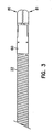
- Forceps 10 is adapted for use internally of the body, for example in connection with endoscopic, laparoscopic or vascular procedures.
- Forceps 10 includes a control handle portion 12 at the proximal end, a middle portion 14 which extends over the main length of the device, and a distal end 16 which includes opposed forceps cutting jaws and distal end of the optical fiber, as is explained in greater detail below.
- the main body or length of the forceps 10 consists of coaxial inner and an outer tubular members.
- the inner tubular member is a hollow plastic tube 20
- the outer tubular member or catheter body is coil 22.
- the coil 22 is a finely wound spiral coil of stainless steel as is generally known and used in catheters and guidewires.
- the outer tubular member could be made using another plastic tube, or a plastic/metal composite structure, in place of coil 22.
- the plastic tube 20 is positioned within coil 22 and these components are dimensioned with respect to each other so that tube 20 may be free to move axially within coil 22 during actuation of the jaws, as is explained below.
- a pair of control wires 40, 41, and the optical fiber 50 Positioned within inner tube 20 are a pair of control wires 40, 41, and the optical fiber 50. These components, together with outer coil 22 and inner plastic tube 20 extend over the main length of the device, from the distal end 16 to the handle portion 12. At the handle, coil 22 and tube 20 pass through a plastic sleeve 24, which serves as a reinforcement and strain relief, into a bore 25 in the tip 13 of the handle 12. The plastic sleeve 24 and the proximal end of the coil 22 are received and secured, as by bonding, in the tip 13 of the handle 12.
- the inner plastic tube 20, control wires 40, 41 and fiber 50 are not secured at tip 13, but pass through bore 25, through a stainless steel reinforcing tube 29 to slider 30, which is movably received in a slot 28 in handle 12.
- Reinforcing tube 29, tube 20 and control wires 40, 41 are secured to slider 30 which together form an actuator mechanism for the forceps 10. Movement of slider 30 causes axial movement of reinforcing tube 29, tube 20 and control wires 40, 41 relative to coil 22, which is used to actuate the cutting jaws.
- Loops 26 and 27 are provided in handle 12 and slider 30, to form finger holes useful in grasping and manipulating the forceps.
- Optical fiber 50 extends through slider 30, and out of handle 12, in a protective cable or sheath 32, for connection to electro-optical units (not shown) which provide the illumination light to the fiber, and which receive and analyze the returned right from the target at distal the end of the forceps.
- the optical biopsy forceps of the present invention may be used with any type of electro-optical technique for guiding the forceps. This may include systems which use viewing or imaging, systems which use illumination with white light to excite dyes in the area of interest, and spectroscopic techniques to identify tissue types by spectral analysis of light returned from tissue illuminated with light of certain wavelengths. Such spectroscopic techniques utilize the property of certain tissue types to reflect or fluoresce light having characteristic wavelengths.
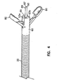
- the distal end 16 of the optical forceps includes a yoke 60, which serves as a mounting member for the cutting jaws.
- Yoke 60 may be machined from stainless steel or formed of other suitable material. It generally has a proximal portion or section indicated by reference number 61. a center section 62, and a distal section 63 having inwardly curved opposing distal end portions 63a and 63b.
- Yoke 60 has a bore 64 running therethrough.
- Each of the opposing distal end portions 63a and 63b has an arc shaped groove 65 (Figs. 5B and 5C) formed therein which defines a guide slot for the distal end of the fiber 50.
- the diameter of the bore defined by the arcuate grooves 65 can be stepped to a smaller size at distal end portions 63a and 63b.
- Sections 61 and 62 are generally circular in section. Section 61 has a diameter corresponding to the inside dimension of coil 22, while section 62 has a diameter corresponding to the outside dimension of coil 22, so that the end of coil 22 may be received and bonded to section 61.
- the proximal end surface 56 of the yoke 60 cooperates with the distal end 21 of the inner tube 20 to provide a limit stop for the fiber tube assembly 52 when it is being advanced within the outer tube 22 to open the jaws.
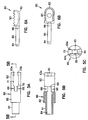
- Center section 62 has a pair of holes 68, 69 which receive pins 72, 73 to hold the jaws in place.
- Distal section 63 is stepped down relative to section 62, as seen in side view in Figs. 2 and 5B, to allow the jaws 80 and 81 to fold against it when the jaws are closed (Fig. 3) so as to have a thin profile for ease of introduction and navigation.
- Distal section 63 also has a vertical slot 70 provided therein which is dimensioned to the size of the mounting ends of the lever arms 85 of the jaws.
- the inner wall 71 of distal section 63 is stepped outwardly relative to the slot 70 to provide clearance for the ends of control wires 40 and 41'.
- jaw 80 and 81 are similar only one is described in detail here.
- the two jaws are mirror-image identical, but with their serrations staggered so that they will mesh.
- jaw 80 has a rearward lever or mounting portion 85, and a distal cup or sample receiving portion 82, which has sharp serrations 83 used to cut the tissue sample.
- the lever portion 85 has a hole 84 formed to receive the pin 72 which thus serves to retain the jaws, and also to acts as the pivot point.
- a hole 86 is provided at the forward apex of the relieved section, to receive the end of control wire 40 (or 41) which is crimped or bent at a right angle at its tip to be effectively captured.
- the control wires are formed of wire which is stiff enough to push against the jaws to open them, but flexible enough to flex as the wires are retracted to pull the jaws together.
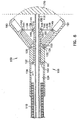
- the distal end 16 of the optical forceps also includes a fiber tube assembly 52. It includes a tube 54 which may be machined from stainless steel, or formed of other suitable material. The end of plastic tube 20 overlaps end 55 of the tube 54 and is bonded to tube 54. The control wires 40, 41 and the optical fiber 50 pass into it from the plastic tube 20. The optical fiber and the control wires pass axially through the tube 54 and are bonded to the tube 54 by epoxy or other suitable adhesive.
- the optical fiber 50 includes a jacket 87 of polyamide or similar material and an outer protective tube 88 made of stainless steel, for example. The jacket 87 extends the length of the optical fiber from its proximal end to its proximal end.
- the protective tube 88 extends from the distal end of the optical fiber to at least a point located within the distal end of tube 54.
- the distal end of the optical fiber 50 is flush with the end of the protective tube 88, and may have a lens or clear epoxy coating, depending on the optical properties desired.
- the protective tube 88 at the distal end of the optical fiber is designed to give strength to prevent damage to the fiber by tweezers and the like when tissue is removed from the biopsy jaws.
- the slider 30 in operation, is retracted toward the back of handle 12 to close the jaws. This causes movement (to the left in Fig. 2) of plastic tube 20, the fiber tube assembly 52, the control wires 40, 41, and the optical fiber 50. This retracts the optical fiber into the yoke 60 and the pulling of the control wires closes the jaws.
- the distal end is of the same narrow diameter as the main body of the forceps catheter, and the closed jaws have a smooth, rounded shape to facilitate introduction and navigation in the vascular, endoscopic or laproscopic systems.
- the cutting jaws are coaxially positioned with respect to the distal end of the optical fiber.
- the forceps jaws can be opened by pushing slider 30 of the control handle forward. This causes movement (to the right in Fig. 2) of plastic tube 20, the fiber tube assembly 52, the control wires 40, 41, and the optical fiber 50.
- the control wires push against the jaws, causing them to open.
- the tip of the optical fiber is axially extended.
- the distal end or tip of the optical fiber is positioned at the distal end of the catheter body with its optical view axis or view axis aligned for a tissue analysis zone adjacent the distal tip of the catheter body and positioned at the area of contact of the cutting jaws when the cutting jaws are operated to their closed cutting position.
- the device may then be used for optical tissue identification.
- slider 30 When an area of disease is identified and a biopsy of it is needed, slider 30 is pulled, retracting the tip of the fiber and simultaneously causing the jaws to close and cut a biopsy sample at the exact place being viewed by the fiber.
- the biopsy sample is cut from the exact tissue site identified by the spectroscopic analysis step without requiring moving or repositioning of the catheter body.
- the forceps may then be withdrawn from the patient to recover the sample for analysis.
- the analysis of the withdrawn sample can be conducted using known laboratory techniques to confirm the identification of the tissue sample made by spectroscopic analysis.
- the optical biopsy forceps of the invention is used for spectroscopically analyzing tissue in the tissue analysis zone adjacent the distal end of the forceps through the use of an electro-optic tissue analysis system connected to the proximal end of the optical fiber.
- the optical biopsy forceps are guided spectroscopically within the body to an area of interest as identified by the spectroscopic analysis of tissue type in the tissue analysis zone adjacent the distal tip of the catheter body.
- FIG. 7 another embodiment of an integrated optical biopsy forceps of the present invention is generally indicated by reference number 90.
- the optical forceps 90 is generally similar to the optical forceps 10 shown in Fig. 1, and accordingly, corresponding elements have been given the same reference number.
- the optical biopsy forceps is adapted for use internally of the body, for example in connection with endoscopic, laparoscopic or vascular procedures.
- Forceps 90 includes a handle portion 91 and an operating lever 92 at the proximal end, a middle portion 14 which extends over the main length of the device, and a distal end 16.
- the distal end 16 includes forceps cutting jaws 80 and 81 and the distal end of the optical fiber 50 which is contained within a plastic tube, corresponding to plastic tube 20 of forceps 10, and pass through a sleeve 24 in the manner illustrated in Figs. 1-6 for the forceps 10.
- the operating lever 92 has its upper end 93 pivoted to the handle 91 by a pivot pin 94.
- the forceps 90 includes a reinforcing tube, corresponding to reinforcing tube 29 of forceps 10, which encloses the fiber optical tube, and control wires 40 and 41.
- the control wires pass around a post 95 and are secured to the operating lever 92 near its upper end 93 located within the handle.
- the optical fiber tube extends out of the handle in a protective sheath 32 as described above with reference to optical biopsy forceps 10.
- Loops 97 are provided in the handle 91 and the operating lever 92, forming finger holes useful in grasping and manipulating the forceps.
- the operating lever also has curved regions 99 forming finger rests, which together with the depending operating lever arrangement of the forceps 90, enhance the ergonomics of the instrument.
- the jaws 80 and 81 are open when the relative position between the handle 91 and the operating lever 92 is as illustrated in Fig. 6.
- the control wires 40 and 41 are drawn around the post 95, retracting the optical fiber and operating the jaws 80 and 81 closed in a manner similar to that described for the operation of forceps 10.
- the control wires are advanced within tube 20, causing the jaws to open.
- the optical biopsy forceps includes an optical fiber 150 and opposed forceps cutting jaws 180 and 181, which can be similar to the optical fiber and the jaws of forceps 10 shown in figs. 1-6.
- the optical fiber 150 of the optical biopsy forceps includes an outer tubular, sheath-like member or catheter body 110, which corresponds to the outer sheath or coil 22 (Fig. 2), and a reinforcement cover 116, which, for example, can be a metal coil or cable, a nylon sheath, or any other suitable cover.
- the reinforced optical fiber is movable axially within the sheath 110.
- the optical biopsy forceps further includes a tubular slide member 120 connected to the optical fiber and movable therewith, and coupled to the jaws 180 and 181 for actuating the jaws 180 and 181 as the optical fiber is moved within the outer sheath 110.
- the optical biopsy forceps includes a suitable handle (not shown) for facilitating actuation of the tubular slide member 120.
- the handle is similar to the handle 12 (Fig. 1) of the optical biopsy forceps 10, but the handle can include any type of actuating mechanism capable of imparting bidirectional axial movement to the optical fiber 150 of the optical biopsy forceps.
- the optical fiber 150 positioned within the outer sheath extends over the main length of the device, from the distal end 106 to the handle.
- the proximal end of the sheath 110 passes through a sleeve, such as sleeve 24, and is secured to the tip of the handle.
- the sleeve provides reinforcement and strain relief where the sheath 110 is attached to the handle.
- the proximal end of the optical fiber 150 also passes through sleeve 24 and is secured to the slider 30 of the handle 12 distally of the proximal end of the optical fiber 150, the end portion of which passes through the slider and out of the handle for connection to suitable electro-optical units in the manner that has been described for the optical fiber 50 of optical biopsy forceps 10.
- the slider 30 of the handle is adapted to push the reinforced optical fiber 150, which in turn pushes the tubular slide member 120, to open the jaws of the optical biopsy forceps and to pull the reinforced optical fiber, pulling the tubular slide member 120, to close the jaws.
- the optical biopsy forceps of the present invention can be used with any type of electro-optical technique for guiding the forceps.
- This may include systems which use viewing or imaging, systems which use illumination with white light to excite dyes in the area of interest, and spectroscopic techniques to identify tissue types by spectral analysis of light returned from tissue illuminated with light of certain wavelengths.
- spectroscopic techniques utilize the property of certain tissue types to reflect or fluoresce light having characteristic wavelengths.
- the sheath 110 is a flexible hollow catheter which can be made a plastic tube, or a plastic/metal composite structure that defines an opening or bore therethrough.
- the outer sheath 110 can be similar to those of disposable biopsy forceps commonly used with colonoscopes used in the upper and lower gastrointestinal tracts, and broncoscopes used in the trachea and bronchus.
- the outer sheath 110 can be a rigid tube, such as those of biopsy forceps commonly used with cystoscopes, colposcopes and laproscopes.
- the optical fiber 150 extends through a central bore 119 formed through a tubular slide member 120 which, in turn, is mounted in a mounting member or jaw support block 122 which serves as a mounting member for the cutting jaws 180, 181.
- the jaw support block 122 can be machined from stainless steel or formed of other suitable material.
- the jaw support block 122 has a bore 124 running therethrough which is generally circular in section.
- the inner dimension of the jaw support block 122 corresponds to the outer dimension of the outer sheath 110 which is secured to the support block in a suitable manner, such as with cement or by crimping.
- the jaws 180, 181 are hinged to the support block 122 which has a pair of holes which receive pins 130, 132 which pass through ears 134 of the jaws to hold the jaws 180, 181 in place.
- the attachment of the jaws to the support block by ears 134 allows the jaws 180, 181 to fold against the front end of the support block when closed so as to have a thin profile for the distal end of the forceps for ease of introduction and navigation.
- the jaw support block 122 has a slot to control travel of the jaws 180 and 181.
- the tubular slide member 120 is mounted in the bore 124 in the jaw support block 122 and is free to move axially within support block 122 during actuation of the jaws.
- the fiber 150 is secured to the tubular slide member 120 in a suitable manner such as with cement.
- the jaws 180, 181 are connected to the tubular slide member 120 by a pair of control links 136, 138, which are rigid members that function as a linkage mechanism connecting the cutting jaws to the tubular slide member.
- Control link 136 has one end 139 connected to tubular slide member 120 by a pin 140.
- the other end 141 of the control link 136 is connected to jaw 180 by a pin 142.
- control link 138 has one end 144 connected to tubular slide member 120 by a pin 146 and its other end 148 connected to jaw 181 by a pin 149.
- axial movement of the optical fiber in the direction of arrow 154 causes axial movement of tubular slide member 120, pivoting the control links 136, 138, about their ends 139 and 144, respectively, drawing the jaws together to actuate the cutting jaws 180, 181.
- the rearward surface 151 at the distal end 152 of the tubular slide member 120 is adapted to engage the forward surface 153 of the jaw support block 122, functioning as a travel limit stop surface to limit the axial movement of the tubular slide member 120 during retraction of the optical fiber 150.
- both the proximal and distal ends of the tubular slide member 120 include limit stops which prevent both over distention and over retraction of the optical fiber 150.
- the optical fiber 150 is fully retracted (by retracting the slider 30 toward the back of the handle) to move the tubular slide member 120 in the direction of the arrow 154 until its rearward surface 151 engages forward surface 153 of the jaw support block 122.
- the control links 136 and 138 have been drawn rearwardly, drawing the jaws 180,181 together so that the jaws are closed.
- the distal end 106 of the forceps is substantially of the same narrow diameter as the outer sheath 116 which defines the main body portion of the optical biopsy forceps, and the closed jaws have a smooth, rounded shape to facilitate introduction and navigation through the biopsy channel of an endoscope, for example.
- the endoscopist advances the optical biopsy forceps through the biopsy channel of the endoscope to the general area of interest, i.e., such as a tissue site or tissue analysis zone with a body, represented by the reference numeral 170.
- the forceps jaws can be opened by advancing the slider 30, thereby advancing the optical fiber 150 forwardly through the handle. This causes the tubular slide member 120 to move forwardly (to the right in Fig. 8), which in turn causes pivoting of the control links 136 and 138. As the control links pivot, the control links push against the jaws, causing the jaws to open. Simultaneously, the distal tip of the optical fiber 150 is axially extended forwardly beyond the jaws. The forceps may then be used for optical tissue identification.
- the slider 30 When an area of disease is identified and if a biopsy of it is needed, the slider 30 is retracted, retracting the optical fiber 150 and thus the tubular slide member 120, retracting the tip of the optical fiber and simultaneously causing the jaws to close and cut a biopsy sample at the exact place that has been located by viewing through the optical fiber.
- the endoscopist holding the instrument by the handle gently pulls back on the slider of the handle, retracting the optical fiber and tubular slide member 120, moving the optical fiber away from the tissue surface.
- the jaws begin to close as the tubular slide member is moved in the direction of the arrow 154.
- the endoscopist gently pushes on the instrument to urge the jaws towards the tissue surface so that a tissue sample will be captured by the jaws as they close.
- the endoscopist pulls the entire assembly away from the tissue surface and then withdraws the optical biopsy forceps from the endoscope so that the specimen tissue can be retrieved.
- the present invention has provided an optical biopsy forceps.
- An important feature of the invention is that the tip of the optical fiber 50 (and optical fiber 150) is coaxial with, and perfectly aligned with, the zone where the two jaws 80, 81 (and jaws 180, 181) intersect and the sample is taken.
- This, together with the slim and compact profile of the device when the jaws are retracted, is a great improvement over prior art devices.
- the fiber optic assembly including the optical fiber and the tubular slide member of the biopsy forceps, can be produced as a disposable assembly, with the rest of the biopsy forceps being produced as a non-disposable unit.
- the major advantage of forceps 100 as compared to forceps 10 is, because the biopsy jaw control wires 40, 41 are not required, larger diameter optical fibers can be used to increase the detected signal relative to noise.
Landscapes
- Health & Medical Sciences (AREA)
- Life Sciences & Earth Sciences (AREA)
- Surgery (AREA)
- Molecular Biology (AREA)
- General Health & Medical Sciences (AREA)
- Pathology (AREA)
- Engineering & Computer Science (AREA)
- Biomedical Technology (AREA)
- Heart & Thoracic Surgery (AREA)
- Medical Informatics (AREA)
- Biodiversity & Conservation Biology (AREA)
- Animal Behavior & Ethology (AREA)
- Nuclear Medicine, Radiotherapy & Molecular Imaging (AREA)
- Public Health (AREA)
- Veterinary Medicine (AREA)
- Endoscopes (AREA)
- Surgical Instruments (AREA)
- Prostheses (AREA)
- Adornments (AREA)
- Gloves (AREA)
Claims (11)
- Forceps de biopsie optique intégré (10), comprenant :un corps de cathéter (20, 22) ayant un orifice (25) à travers celui-ci et ayant des extrémités proximale et distale (16) ; etune fibre optique (50) s'étendant à travers le corps de cathéter (20, 22) et adaptée à son extrémité proximale pour connexion à un système d'analyse de tissu électro-optique, l'extrémité distale de la fibre optique (50) étant positionnée à l'extrémité distale du corps de cathéter (20, 22) avec son axe d'observation optique adapté pour être aligné avec une zone d'analyse de tissu (170) adjacente à la pointe distale du corps de cathéter (20, 22) ;des mâchoires coupantes (80,81) montées à l'extrémité distale du corps de cathéter (20, 22) pour l'ouverture et la fermeture sélectives dans un mouvement de coupe de biopsie ; etun mécanisme d'actionnement (30, 20, 52, 40, 41) connecté de manière opératoire aux mâchoires coupantes (80, 81) pour commander sélectivement l'ouverture et la fermeture des mâchoires coupantes (80, 81) pour découper un échantillon de biopsie dans la zone d'analyse de tissu ; caractérisé en ce que le corps de cathéter est flexible et lesdites mâchoires coupantes sont positionnées de manière à ce qu'elles aient une position de coupe fermée qui est située dans l'axe d'observation optique et dans le champ de vision de la fibre optique (50) dans la zone d'analyse de tissu.
- Forceps selon la revendication 1, dans lequel le mécanisme d'actionnement (30, 20, 52, 40, 41) comprend un organe coulissant tubulaire (120) monté dans l'extrémité distale du corps de cathéter (20, 22) et adapté pour un mouvement axial par rapport au corps de cathéter (20, 22) et un mécanisme de liaison (136, 138) connectant les mâchoires coupantes (80, 81) à l'organe coulissant tubulaire (120).
- Forceps selon la revendication 2, dans lequel la fibre optique (50) est mobile axialement par rapport au corps de cathéter (20, 22) entre une position avancée et une position retirée, l'organe coulissant tubulaire (120) étant fixé à la fibre optique (50) et mobile avec la fibre optique (50) pour commander depuis l'extrémité proximale du corps de cathéter (20, 22) l'ouverture et la fermeture des mâchoires coupantes (80, 81).
- Forceps selon la revendication 2, dans lequel le mécanisme d'actionnement (30, 20, 52, 40, 41) est couplé de manière opératoire à la fibre optique (50) pour retirer la pointe distale de la fibre optique (50) lorsque les mâchoires coupantes (80, 81) se ferment conjointement.
- Forceps selon la revendication 2, comprenant un organe de montage (60) fixé au corps de cathéter (20, 22) à l'extrémité distale du corps de cathéter (20, 22) pour monter les mâchoires coupantes (80, 81), dans lequel ledit organe coulissant tubulaire (120) est susceptible de coopérer avec un organe de montage (60) pour définir un premier arrêt de limite de course (161, 163) pour éviter une distension excessive de ladite fibre optique et un second arrêt de limite de course (151, 153) pour éviter un retrait excessif de ladite fibre optique.
- Forceps selon la revendication 1, comprenant, de plus, un organe de montage (60) connecté au corps de cathéter (20, 22) à l'extrémité distale du corps de cathéter pour monter les mâchoires coupantes (80, 81).
- Forceps selon la revendication 1, dans lequel le mécanisme d'actionnement (30, 20, 52, 40, 41) comprend un organe coulissant tubulaire (120) couplé aux mâchoires coupantes (80, 81), et le mécanisme d'actionnement (30, 20, 51, 40, 41) peut être actionné pour ouvrir et fermer les mâchoires coupantes (80, 81) par mouvement axial de l'organe coulissant tubulaire (120).
- Forceps selon la revendication 7, comprenant, de plus, une poignée (12) à l'extrémité proximale du corps de cathéter (20, 22), dans lequel la poignée (12) reçoit l'extrémité proximale de la fibre optique (50) pour connexion de celle-ci à un système d'analyse de tissu électro-optique, le corps de cathéter (20, 22) est fixé à la poignée (12) et la fibre optique (50) est mobile par rapport à la poignée (12).
- Forceps selon la revendication 2, dans lequel le mécanisme de liaison (136, 138) comprend des première et seconde liaisons (136, 138) pour connecter les mâchoires coupantes (80, 81) audit organe coulissant tubulaire (120).
- Forceps selon la revendication 9, dans lequel chacune des mâchoires coupantes (80, 81) comprend une partie de montage (85) et une partie receveuse d'échantillon (82) et dans lequel les première et seconde liaisons (136, 138) sont connectées à une mâchoire coupante respective (80, 81) en position intermédiaire entre la partie de montage (85) et la partie receveuse d'échantillon (82).
- Forceps selon la revendication 1, comprenant, de plus, un organe de montage (60) fixé au corps de cathéter (20, 22) à une extrémité distale du corps de cathéter (20, 22) pour monter les mâchoires coupantes (80, 81) et comprenant, de plus, un organe coulissant tubulaire (120) monté dans l'extrémité distale du corps de cathéter (20, 22), dans lequel ledit organe coulissant tubulaire (120) est mobile axialement par rapport audit organe de montage (60) et ledit organe coulissant tubulaire (120) est susceptible de coopérer avec ledit organe de montage (60) pour définir un premier arrêt de limite de course (161, 163) pour éviter une distension excessive de ladite fibre optique et un second arrêt de limite de course (151, 153) pour éviter un retrait excessif de ladite fibre optique.
Applications Claiming Priority (3)
| Application Number | Priority Date | Filing Date | Title |
|---|---|---|---|
| US08/643,912 US5843000A (en) | 1996-05-07 | 1996-05-07 | Optical biopsy forceps and method of diagnosing tissue |
| PCT/US1997/007784 WO1997041777A1 (fr) | 1996-05-07 | 1997-05-07 | Pince a biopsie optique et methode de diagnostic de tissus |
| US643912 | 2006-12-22 |
Publications (2)
| Publication Number | Publication Date |
|---|---|
| EP0902647A1 EP0902647A1 (fr) | 1999-03-24 |
| EP0902647B1 true EP0902647B1 (fr) | 2005-12-28 |
Family
ID=24582678
Family Applications (1)
| Application Number | Title | Priority Date | Filing Date |
|---|---|---|---|
| EP97925486A Expired - Lifetime EP0902647B1 (fr) | 1996-05-07 | 1997-05-07 | Pince a biopsie optique |
Country Status (7)
| Country | Link |
|---|---|
| US (1) | US5843000A (fr) |
| EP (1) | EP0902647B1 (fr) |
| JP (1) | JP3220165B2 (fr) |
| AT (1) | ATE314008T1 (fr) |
| CA (1) | CA2253646C (fr) |
| DE (1) | DE69734978T2 (fr) |
| WO (1) | WO1997041777A1 (fr) |
Cited By (3)
| Publication number | Priority date | Publication date | Assignee | Title |
|---|---|---|---|---|
| CN104284635A (zh) * | 2012-01-20 | 2015-01-14 | 皇家飞利浦有限公司 | 电手术系统、电手术设备和用于操作电手术系统的方法 |
| EP2519300B1 (fr) | 2009-12-29 | 2020-08-12 | Acclarent, Inc. | Système de traitement d'un tissu cible dans la trompe d'eustache |
| WO2025174747A1 (fr) * | 2024-02-12 | 2025-08-21 | Boston Scientific Scimed, Inc. | Ensemble mâchoire pour dispositifs médicaux |
Families Citing this family (155)
| Publication number | Priority date | Publication date | Assignee | Title |
|---|---|---|---|---|
| US5762613A (en) * | 1996-05-07 | 1998-06-09 | Spectrascience, Inc. | Optical biopsy forceps |
| US6296608B1 (en) * | 1996-07-08 | 2001-10-02 | Boston Scientific Corporation | Diagnosing and performing interventional procedures on tissue in vivo |
| CA2283949A1 (fr) | 1997-03-13 | 1998-09-17 | Haishan Zeng | Procede et dispositif de detection du rejet d'un tissu greffe |
| US6174291B1 (en) * | 1998-03-09 | 2001-01-16 | Spectrascience, Inc. | Optical biopsy system and methods for tissue diagnosis |
| US6066102A (en) | 1998-03-09 | 2000-05-23 | Spectrascience, Inc. | Optical biopsy forceps system and method of diagnosing tissue |
| US6149607A (en) * | 1998-08-04 | 2000-11-21 | Endonetics, Inc. | Multiple sample biopsy device |
| US6139508A (en) * | 1998-08-04 | 2000-10-31 | Endonetics, Inc. | Articulated medical device |
| ITCE990004A1 (it) | 1999-10-25 | 2000-01-25 | Mario Immacolato Paternuosto | Valve per pinza da biopsia in endoscopia digestiva |
| US7228165B1 (en) | 2000-06-26 | 2007-06-05 | Boston Scientific Scimed, Inc. | Apparatus and method for performing a tissue resection procedure |
| ATE454845T1 (de) * | 2000-10-30 | 2010-01-15 | Gen Hospital Corp | Optische systeme zur gewebeanalyse |
| US9295391B1 (en) | 2000-11-10 | 2016-03-29 | The General Hospital Corporation | Spectrally encoded miniature endoscopic imaging probe |
| GB0103030D0 (en) | 2001-02-07 | 2001-03-21 | Univ London | Spectrum processing and processor |
| WO2002088684A1 (fr) | 2001-04-30 | 2002-11-07 | The General Hospital Corporation | Procede et appareil permettant d'ameliorer la clarte et la sensibilite de l'image en tomographie a coherence optique au moyen d'une interaction permettant de controler les proprietes focales et la synchronisation de coherence |
| WO2002088705A2 (fr) | 2001-05-01 | 2002-11-07 | The General Hospital Corporation | Procede et appareil pour determiner un type de plaque d'atherosclerose par mesure de proprietes optiques de tissu |
| US7094245B2 (en) * | 2001-10-05 | 2006-08-22 | Scimed Life Systems, Inc. | Device and method for through the scope endoscopic hemostatic clipping |
| US6980299B1 (en) | 2001-10-16 | 2005-12-27 | General Hospital Corporation | Systems and methods for imaging a sample |
| US7169167B2 (en) * | 2001-12-04 | 2007-01-30 | Scimed Life Systems, Inc. | Endoscopic apparatus and method |
| AU2003207507A1 (en) | 2002-01-11 | 2003-07-30 | Gen Hospital Corp | Apparatus for oct imaging with axial line focus for improved resolution and depth of field |
| US7355716B2 (en) | 2002-01-24 | 2008-04-08 | The General Hospital Corporation | Apparatus and method for ranging and noise reduction of low coherence interferometry LCI and optical coherence tomography OCT signals by parallel detection of spectral bands |
| JP4131011B2 (ja) * | 2002-04-09 | 2008-08-13 | Hoya株式会社 | 内視鏡用嘴状処置具 |
| US7037276B2 (en) * | 2002-07-02 | 2006-05-02 | Precision Medical Devices, Inc. | Biopsy device |
| DE10255082A1 (de) * | 2002-11-20 | 2004-06-17 | Aesculap Ag & Co. Kg | Endoskop |
| US7761139B2 (en) | 2003-01-24 | 2010-07-20 | The General Hospital Corporation | System and method for identifying tissue using low-coherence interferometry |
| US7643153B2 (en) | 2003-01-24 | 2010-01-05 | The General Hospital Corporation | Apparatus and method for ranging and noise reduction of low coherence interferometry LCI and optical coherence tomography OCT signals by parallel detection of spectral bands |
| CA2519937C (fr) | 2003-03-31 | 2012-11-20 | Guillermo J. Tearney | Reduction de granularite dans la tomographie par coherence optique au moyen d'une composition angulaire par codage de longueur de trajet |
| US20040199052A1 (en) | 2003-04-01 | 2004-10-07 | Scimed Life Systems, Inc. | Endoscopic imaging system |
| US7578786B2 (en) | 2003-04-01 | 2009-08-25 | Boston Scientific Scimed, Inc. | Video endoscope |
| US8118732B2 (en) | 2003-04-01 | 2012-02-21 | Boston Scientific Scimed, Inc. | Force feedback control system for video endoscope |
| US7591783B2 (en) | 2003-04-01 | 2009-09-22 | Boston Scientific Scimed, Inc. | Articulation joint for video endoscope |
| US20050245789A1 (en) | 2003-04-01 | 2005-11-03 | Boston Scientific Scimed, Inc. | Fluid manifold for endoscope system |
| ES2310744T3 (es) | 2003-06-06 | 2009-01-16 | The General Hospital Corporation | Fuente de luz sintonizable en longitudes de onda. |
| US20040260337A1 (en) | 2003-06-18 | 2004-12-23 | Scimed Life Systems, Inc. | Endoscopic instruments and methods of manufacture |
| US8469993B2 (en) | 2003-06-18 | 2013-06-25 | Boston Scientific Scimed, Inc. | Endoscopic instruments |
| US7588545B2 (en) | 2003-09-10 | 2009-09-15 | Boston Scientific Scimed, Inc. | Forceps and collection assembly with accompanying mechanisms and related methods of use |
| US8034003B2 (en) | 2003-09-11 | 2011-10-11 | Depuy Mitek, Inc. | Tissue extraction and collection device |
| US7611473B2 (en) * | 2003-09-11 | 2009-11-03 | Ethicon, Inc. | Tissue extraction and maceration device |
| US8012128B2 (en) * | 2003-09-30 | 2011-09-06 | Ethicon Endo-Surgery Inc. | Button latching system for a trocar |
| EP2278287B1 (fr) | 2003-10-27 | 2016-09-07 | The General Hospital Corporation | Procédé et appareil de l'imagerie optique avec de l'interférométrie dans le domaine de fréquence |
| US7942896B2 (en) | 2003-11-25 | 2011-05-17 | Scimed Life Systems, Inc. | Forceps and collection assembly and related methods of use and manufacture |
| EP1687587B1 (fr) | 2003-11-28 | 2020-01-08 | The General Hospital Corporation | Procede et appareil d'imagerie codee de maniere spectrale tridimensionnelle |
| US8018598B2 (en) | 2004-05-29 | 2011-09-13 | The General Hospital Corporation | Process, system and software arrangement for a chromatic dispersion compensation using reflective layers in optical coherence tomography (OCT) imaging |
| AU2005270037B2 (en) | 2004-07-02 | 2012-02-09 | The General Hospital Corporation | Endoscopic imaging probe comprising dual clad fibre |
| JP5053845B2 (ja) | 2004-08-06 | 2012-10-24 | ザ ジェネラル ホスピタル コーポレイション | 光学コヒーレンス断層撮影法を使用して試料中の少なくとも1つの位置を決定するための方法、システムおよびソフトウェア装置 |
| JP5324095B2 (ja) | 2004-08-24 | 2013-10-23 | ザ ジェネラル ホスピタル コーポレイション | 血管セグメントを画像化する方法および装置 |
| EP1989997A1 (fr) | 2004-08-24 | 2008-11-12 | The General Hospital Corporation | Procèdé, Système et logiciel pour la mesure de la contrainte mécanique et des propriétés élastiques d'un echantillon |
| US7365859B2 (en) | 2004-09-10 | 2008-04-29 | The General Hospital Corporation | System and method for optical coherence imaging |
| EP1804638B1 (fr) | 2004-09-29 | 2012-12-19 | The General Hospital Corporation | Systeme et procede d'imagerie a coherence optique |
| WO2006039511A2 (fr) | 2004-09-30 | 2006-04-13 | Boston Scientific Scimed, Inc. | Systeme et procede pour retirer une obstruction |
| US7479106B2 (en) | 2004-09-30 | 2009-01-20 | Boston Scientific Scimed, Inc. | Automated control of irrigation and aspiration in a single-use endoscope |
| US8083671B2 (en) | 2004-09-30 | 2011-12-27 | Boston Scientific Scimed, Inc. | Fluid delivery system for use with an endoscope |
| US8199187B2 (en) | 2004-09-30 | 2012-06-12 | Boston Scientific Scimed, Inc. | Adapter for use with digital imaging medical device |
| US7241263B2 (en) | 2004-09-30 | 2007-07-10 | Scimed Life Systems, Inc. | Selectively rotatable shaft coupler |
| CA2581079A1 (fr) | 2004-09-30 | 2006-04-13 | Boston Scientific Scimed, Inc. | Systeme endoscopique multifonctionnel pour une utilisation dans des applications electrochirurgicales |
| US7597662B2 (en) | 2004-09-30 | 2009-10-06 | Boston Scientific Scimed, Inc. | Multi-fluid delivery system |
| EP1807722B1 (fr) | 2004-11-02 | 2022-08-10 | The General Hospital Corporation | Dispositif rotationnel a fibres optiques, systeme optique pour imager un echantillon |
| EP2278266A3 (fr) | 2004-11-24 | 2011-06-29 | The General Hospital Corporation | Interféromètre à chemin commun pour OCT endoscopique |
| WO2006058346A1 (fr) | 2004-11-29 | 2006-06-01 | The General Hospital Corporation | Ensembles, dispositifs, endoscopes, catheters et methodes d'imagerie optique permettant d'eclairer et de detecter simultanement plusieurs points sur un echantillon |
| US7794413B2 (en) * | 2005-04-19 | 2010-09-14 | Ev3, Inc. | Libraries and data structures of materials removed by debulking catheters |
| EP2325803A1 (fr) | 2005-04-28 | 2011-05-25 | The General Hospital Corporation | Evaluation des informations de tomographie par cohérence optique pour une structure anatomique |
| US7846107B2 (en) | 2005-05-13 | 2010-12-07 | Boston Scientific Scimed, Inc. | Endoscopic apparatus with integrated multiple biopsy device |
| US7762960B2 (en) | 2005-05-13 | 2010-07-27 | Boston Scientific Scimed, Inc. | Biopsy forceps assemblies |
| US8097003B2 (en) | 2005-05-13 | 2012-01-17 | Boston Scientific Scimed, Inc. | Endoscopic apparatus with integrated variceal ligation device |
| EP1887926B1 (fr) | 2005-05-31 | 2014-07-30 | The General Hospital Corporation | Systeme et procede qui utilisent des techniques d'interferometrie d'heterodyne a codage spectral pour l'imagerie |
| EP1889037A2 (fr) | 2005-06-01 | 2008-02-20 | The General Hospital Corporation | Appareil, methode et systeme pour effectuer une imagerie de domaine de frequence optique a resolution de phase |
| DE602006017558D1 (de) | 2005-08-09 | 2010-11-25 | Gen Hospital Corp | Gerät und verfahren zur durchführung von polarisationsbasierter quadraturdemodulation bei optischer kohärenztomographie |
| US8052597B2 (en) | 2005-08-30 | 2011-11-08 | Boston Scientific Scimed, Inc. | Method for forming an endoscope articulation joint |
| EP1940286A1 (fr) | 2005-09-29 | 2008-07-09 | General Hospital Corporation | Procede et appareil destines a un procede pour visualiser et analyser un ou plusieurs echantillons biologiques avec des resolutions augmentant progressivement |
| JP5203951B2 (ja) | 2005-10-14 | 2013-06-05 | ザ ジェネラル ホスピタル コーポレイション | スペクトル及び周波数符号化蛍光画像形成 |
| US20070093703A1 (en) * | 2005-10-24 | 2007-04-26 | Sievert Chester E Jr | System and method for non-endoscopic optical biopsy detection of diseased tissue |
| US7796270B2 (en) | 2006-01-10 | 2010-09-14 | The General Hospital Corporation | Systems and methods for generating data based on one or more spectrally-encoded endoscopy techniques |
| WO2007084903A2 (fr) | 2006-01-19 | 2007-07-26 | The General Hospital Corporation | Dispositif de collecte d'information pour une structure utilisant des techniques d'endoscopie à codage spectral, et procédé d'élaboration correspondant |
| US7967759B2 (en) | 2006-01-19 | 2011-06-28 | Boston Scientific Scimed, Inc. | Endoscopic system with integrated patient respiratory status indicator |
| CN101384212A (zh) | 2006-01-19 | 2009-03-11 | 通用医疗公司 | 通过上皮内腔器官束扫描对上皮内腔器官进行光学成像的方法和系统 |
| US9186066B2 (en) | 2006-02-01 | 2015-11-17 | The General Hospital Corporation | Apparatus for applying a plurality of electro-magnetic radiations to a sample |
| WO2007149601A2 (fr) | 2006-02-01 | 2007-12-27 | The General Hospital Corporation | Appareil destiné à commander au moins l'une d'au moins deux sections d'au moins une fibre |
| US10426548B2 (en) | 2006-02-01 | 2019-10-01 | The General Hosppital Corporation | Methods and systems for providing electromagnetic radiation to at least one portion of a sample using conformal laser therapy procedures |
| EP3143926B1 (fr) | 2006-02-08 | 2020-07-01 | The General Hospital Corporation | Procédés, agencements et systèmes pour obtenir des informations associées à un prélèvement anatomique utilisant la microscopie optique |
| US7989207B2 (en) * | 2006-02-17 | 2011-08-02 | Tyco Healthcare Group Lp | Testing lumenectomy samples for markers of non-vascular diseases |
| JP2009527770A (ja) | 2006-02-24 | 2009-07-30 | ザ ジェネラル ホスピタル コーポレイション | 角度分解型のフーリエドメイン光干渉断層撮影法を遂行する方法及びシステム |
| US8888684B2 (en) | 2006-03-27 | 2014-11-18 | Boston Scientific Scimed, Inc. | Medical devices with local drug delivery capabilities |
| US7742173B2 (en) | 2006-04-05 | 2010-06-22 | The General Hospital Corporation | Methods, arrangements and systems for polarization-sensitive optical frequency domain imaging of a sample |
| US7955255B2 (en) | 2006-04-20 | 2011-06-07 | Boston Scientific Scimed, Inc. | Imaging assembly with transparent distal cap |
| US8202265B2 (en) | 2006-04-20 | 2012-06-19 | Boston Scientific Scimed, Inc. | Multiple lumen assembly for use in endoscopes or other medical devices |
| EP3150110B1 (fr) | 2006-05-10 | 2020-09-02 | The General Hospital Corporation | Processus, agencements et systèmes pour fournir une imagerie de domaine de fréquence d'un échantillon |
| US7782464B2 (en) * | 2006-05-12 | 2010-08-24 | The General Hospital Corporation | Processes, arrangements and systems for providing a fiber layer thickness map based on optical coherence tomography images |
| DE102006028001B4 (de) * | 2006-06-14 | 2009-11-26 | Paul Peschke Gmbh | Chirurgische Greifzange |
| EP2054712B1 (fr) | 2006-08-25 | 2015-10-07 | The General Hospital Corporation | Appareil et procédés permettant d'améliorer l'imagerie de tomographie par cohérence optique mettant en oeuvre des techniques de filtrage volumétrique |
| WO2008049118A2 (fr) | 2006-10-19 | 2008-04-24 | The General Hospital Corporation | Dispositif et procédé d'obtention et de fourniture d'informations d'image associées à au moins une portion d' échantillon et permettant de réaliser une telle portion |
| WO2008089406A2 (fr) | 2007-01-19 | 2008-07-24 | The General Hospital Corporation | Appareil et procédé pour contrôler la profondeur de télémétrie dans une imagerie de domaine de fréquence optique |
| WO2008089342A1 (fr) | 2007-01-19 | 2008-07-24 | The General Hospital Corporation | Réflexion de disque rotatif pour balayage de longueurs d'onde rapide de lumière à large bande dispersée |
| CN101686828A (zh) * | 2007-02-19 | 2010-03-31 | 多种活检标本有限责任公司 | 用于获取一个或多个样本的活检钳 |
| EP2602651A3 (fr) | 2007-03-23 | 2014-08-27 | The General Hospital Corporation | Procédés, agencements et appareil pour utiliser un laser à balayage de longueur d'ondes utilisant un balayage angulaire et des procédures de dispersion |
| US10534129B2 (en) | 2007-03-30 | 2020-01-14 | The General Hospital Corporation | System and method providing intracoronary laser speckle imaging for the detection of vulnerable plaque |
| US8045177B2 (en) | 2007-04-17 | 2011-10-25 | The General Hospital Corporation | Apparatus and methods for measuring vibrations using spectrally-encoded endoscopy |
| US8115919B2 (en) | 2007-05-04 | 2012-02-14 | The General Hospital Corporation | Methods, arrangements and systems for obtaining information associated with a sample using optical microscopy |
| BRPI0814191A2 (pt) * | 2007-06-26 | 2015-01-27 | Restoration Robotics Inc | Ferramentas de captação de unidade folicular incluindo dispositivos e seu uso para remover o tecido conectivo |
| DE102007034577A1 (de) * | 2007-07-13 | 2009-01-15 | Karl Storz Gmbh & Co. Kg | Medizinisches Instrument |
| WO2009018456A2 (fr) | 2007-07-31 | 2009-02-05 | The General Hospital Corporation | Systèmes et procédés pour fournir des motifs de balayage de faisceau pour une imagerie dans le domaine de la fréquence optique doppler de vitesse élevée |
| EP2191254B1 (fr) | 2007-08-31 | 2017-07-19 | The General Hospital Corporation | Systeme et procede pour une microscopie par fluorescence a auto-interference, et support lisible par ordinateur associe à ceux-ci |
| WO2009059034A1 (fr) | 2007-10-30 | 2009-05-07 | The General Hospital Corporation | Système et procédé permettant une détection de mode de gaine |
| US11123047B2 (en) | 2008-01-28 | 2021-09-21 | The General Hospital Corporation | Hybrid systems and methods for multi-modal acquisition of intravascular imaging data and counteracting the effects of signal absorption in blood |
| US9332942B2 (en) | 2008-01-28 | 2016-05-10 | The General Hospital Corporation | Systems, processes and computer-accessible medium for providing hybrid flourescence and optical coherence tomography imaging |
| US8221418B2 (en) | 2008-02-07 | 2012-07-17 | Tyco Healthcare Group Lp | Endoscopic instrument for tissue identification |
| US8593619B2 (en) | 2008-05-07 | 2013-11-26 | The General Hospital Corporation | System, method and computer-accessible medium for tracking vessel motion during three-dimensional coronary artery microscopy |
| JP5795531B2 (ja) | 2008-06-20 | 2015-10-14 | ザ ジェネラル ホスピタル コーポレイション | フューズドファイバオプティックカプラ構造、及びその使用方法 |
| WO2010009136A2 (fr) | 2008-07-14 | 2010-01-21 | The General Hospital Corporation | Appareil et procédés d'endoscopie couleur |
| CN107260231A (zh) | 2008-10-20 | 2017-10-20 | 脊柱诊察公司 | 用于进入和察看脊柱的牵开器套管系统 |
| EP2359121A4 (fr) | 2008-12-10 | 2013-08-14 | Gen Hospital Corp | Systèmes, appareil et procédés d'extension de la plage de profondeur d'imagerie de tomographie par cohérence optique, par le biais du sous-échantillonnage optique |
| JP2012515930A (ja) | 2009-01-26 | 2012-07-12 | ザ ジェネラル ホスピタル コーポレーション | 広視野の超解像顕微鏡を提供するためのシステム、方法及びコンピューターがアクセス可能な媒体 |
| US9178330B2 (en) | 2009-02-04 | 2015-11-03 | The General Hospital Corporation | Apparatus and method for utilization of a high-speed optical wavelength tuning source |
| US9351642B2 (en) | 2009-03-12 | 2016-05-31 | The General Hospital Corporation | Non-contact optical system, computer-accessible medium and method for measurement at least one mechanical property of tissue using coherent speckle technique(s) |
| BR112012001042A2 (pt) | 2009-07-14 | 2016-11-22 | Gen Hospital Corp | equipamento e método de medição do fluxo de fluído dentro de estrutura anatômica. |
| US9339341B2 (en) * | 2010-02-08 | 2016-05-17 | Intuitive Surgical Operations, Inc. | Direct pull surgical gripper |
| EP2542145B1 (fr) | 2010-03-05 | 2020-08-12 | The General Hospital Corporation | Systèmes qui procurent des images microscopiques d'au moins une structure anatomique à une résolution particulière |
| US9737320B2 (en) * | 2010-03-18 | 2017-08-22 | Covidien Lp | Surgical grasper with integrated probe |
| US9069130B2 (en) | 2010-05-03 | 2015-06-30 | The General Hospital Corporation | Apparatus, method and system for generating optical radiation from biological gain media |
| US9795301B2 (en) | 2010-05-25 | 2017-10-24 | The General Hospital Corporation | Apparatus, systems, methods and computer-accessible medium for spectral analysis of optical coherence tomography images |
| EP2575597B1 (fr) | 2010-05-25 | 2022-05-04 | The General Hospital Corporation | Appareil pour fournir une imagerie optique de structures et de compositions |
| WO2011153434A2 (fr) | 2010-06-03 | 2011-12-08 | The General Hospital Corporation | Appareil et procédé pour dispositifs de structures d'imagerie, dans ou sur un ou plusieurs organes luminaux |
| WO2012033838A2 (fr) | 2010-09-07 | 2012-03-15 | Yacoubian Stephan V | Instrument chirurgical à usage multiple |
| JP5859009B2 (ja) * | 2010-09-23 | 2016-02-10 | アルファテック スパイン, インコーポレイテッド | クランプ棘間スペーサ装置及び使用方法 |
| SI2627268T1 (sl) | 2010-10-11 | 2017-10-30 | Cook Medical Technologies Llc | Medicinske naprave s snemljivimi vrtljivimi čeljustmi |
| JP5883018B2 (ja) | 2010-10-27 | 2016-03-09 | ザ ジェネラル ホスピタル コーポレイション | 少なくとも1つの血管内部の血圧を測定するための装置、システム、および方法 |
| US8777898B2 (en) | 2011-01-31 | 2014-07-15 | Boston Scientific Scimed, Inc. | Medical devices having releasable coupling |
| US8721077B2 (en) | 2011-04-29 | 2014-05-13 | The General Hospital Corporation | Systems, methods and computer-readable medium for determining depth-resolved physical and/or optical properties of scattering media by analyzing measured data over a range of depths |
| WO2013013049A1 (fr) | 2011-07-19 | 2013-01-24 | The General Hospital Corporation | Systèmes, procédés, appareils et supports accessibles par ordinateur permettant de produire une compensation de dispersion en mode polarisation dans la tomographie à cohérence optique |
| EP2748587B1 (fr) | 2011-08-25 | 2021-01-13 | The General Hospital Corporation | Procédés et arrangements permettant de mettre en oeuvre des procédures de tomographie par cohérence micro-optique |
| US9341783B2 (en) | 2011-10-18 | 2016-05-17 | The General Hospital Corporation | Apparatus and methods for producing and/or providing recirculating optical delay(s) |
| US10398508B2 (en) * | 2012-02-07 | 2019-09-03 | Joe Denton Brown | Protective sheath and method of using same for laser surgery |
| CN102599941A (zh) * | 2012-03-01 | 2012-07-25 | 王宝根 | 蓄光照明活检钳 |
| US9629528B2 (en) | 2012-03-30 | 2017-04-25 | The General Hospital Corporation | Imaging system, method and distal attachment for multidirectional field of view endoscopy |
| EP2852315A4 (fr) | 2012-05-21 | 2016-06-08 | Gen Hospital Corp | Appareil, dispositif et procédé pour microscopie par capsule |
| JP6227652B2 (ja) | 2012-08-22 | 2017-11-08 | ザ ジェネラル ホスピタル コーポレイション | ソフトリソグラフィを用いてミニチュア内視鏡を製作するためのシステム、方法、およびコンピュータ・アクセス可能媒体 |
| US9259211B2 (en) | 2012-12-24 | 2016-02-16 | Transmed7, Llc | Automated, selectable, soft tissue excision biopsy devices and methods |
| US10893806B2 (en) | 2013-01-29 | 2021-01-19 | The General Hospital Corporation | Apparatus, systems and methods for providing information regarding the aortic valve |
| WO2014121082A1 (fr) | 2013-02-01 | 2014-08-07 | The General Hospital Corporation | Agencement d'objectif pour endomicroscopie confocale |
| WO2014144709A2 (fr) | 2013-03-15 | 2014-09-18 | The General Hospital Corporation | Procédés et systèmes de caractérisation d'objet |
| EP2997354A4 (fr) | 2013-05-13 | 2017-01-18 | The General Hospital Corporation | Détection de la phase et de l'amplitude d'une fluorescence auto-interférente |
| EP3021735A4 (fr) | 2013-07-19 | 2017-04-19 | The General Hospital Corporation | Détermination de mouvement oculaire au moyen d'une imagerie de la rétine avec rétroaction d'un mouvement de l'oeil par imagerie de la rétine et fournir des informations en retour pour l'acquisition de signaux venant de la rétine |
| WO2015009932A1 (fr) | 2013-07-19 | 2015-01-22 | The General Hospital Corporation | Appareil d'imagerie et procédé utilisant une endoscopie à champ de vision multidirectionnel |
| WO2015013651A2 (fr) | 2013-07-26 | 2015-01-29 | The General Hospital Corporation | Système, appareil et procédé utilisant une dispersion optique pour réaliser une tomographie en cohérence optique dans le domaine de fourier |
| US11020182B1 (en) * | 2013-09-30 | 2021-06-01 | Michael Feloney | Tactile feedback for surgical robots |
| WO2015105870A1 (fr) | 2014-01-08 | 2015-07-16 | The General Hospital Corporation | Procédé et appareil pour imagerie microscopique |
| US10736494B2 (en) | 2014-01-31 | 2020-08-11 | The General Hospital Corporation | System and method for facilitating manual and/or automatic volumetric imaging with real-time tension or force feedback using a tethered imaging device |
| US10228556B2 (en) | 2014-04-04 | 2019-03-12 | The General Hospital Corporation | Apparatus and method for controlling propagation and/or transmission of electromagnetic radiation in flexible waveguide(s) |
| JP2017525435A (ja) | 2014-07-25 | 2017-09-07 | ザ ジェネラル ホスピタル コーポレイション | インビボ・イメージングおよび診断のための機器、デバイスならびに方法 |
| USD806873S1 (en) * | 2016-02-03 | 2018-01-02 | Karl Storz Gmbh & Co. Kg | Optical forceps |
| USD796676S1 (en) * | 2016-02-03 | 2017-09-05 | Karl Storz Gmbh & Co. Kg | Optical forceps |
| JP7170340B2 (ja) | 2017-08-04 | 2022-11-14 | ユニバーシティ・カレッジ・コークーナショナル・ユニバーシティ・オブ・アイルランド,コーク | 組織貫通外科用システム及び方法 |
| EP3709896B1 (fr) * | 2017-11-15 | 2026-02-11 | United States Endoscopy Group, Inc. | Plateforme d'actionnement d'effecteurs terminaux |
| CN108066017B (zh) * | 2017-12-08 | 2023-10-17 | 苏州朗开医疗技术有限公司 | 一种电视辅助胸腔镜术中病灶探测定位方法及装置 |
| GB2579343A (en) * | 2018-11-02 | 2020-06-24 | Holmin Staffan | Device |
| CN112168236B (zh) * | 2020-11-09 | 2024-11-15 | 惠州市美好创亿医疗科技有限公司 | 侧取样活检钳 |
| CN119033322B (zh) * | 2024-10-30 | 2025-03-04 | 富利凯医疗用品(东莞)有限公司 | 一种纤维支气管镜 |
| CN119366974B (zh) * | 2025-01-02 | 2025-03-28 | 中国医学科学院北京协和医院 | 一种活检取样器操作部及具备其的活检取样器 |
Family Cites Families (25)
| Publication number | Priority date | Publication date | Assignee | Title |
|---|---|---|---|---|
| US3074408A (en) * | 1961-05-22 | 1963-01-22 | Martin H Chester | Ureteral stone extractor and dilator |
| US3924608A (en) * | 1973-05-23 | 1975-12-09 | Olympus Optical Co | Endoscope |
| DK131542C (da) * | 1974-02-06 | 1976-02-09 | Akad Tekn Videnskaber | Kirurgisk instrument til udtagning af biologiske prover |
| JPS5933388B2 (ja) * | 1976-03-19 | 1984-08-15 | 高美 上原 | 単独操作可能な生検用フアイバ−スコ−プ |
| GB2125702B (en) * | 1982-03-16 | 1985-07-24 | Laserscope Inc | Surgical device for internal operations |
| US4557255A (en) * | 1983-08-22 | 1985-12-10 | Goodman Tobias M | Ureteroscope |
| JPS60104915A (ja) * | 1983-11-11 | 1985-06-10 | Fuji Photo Optical Co Ltd | 内視鏡 |
| DE3347671A1 (de) * | 1983-12-31 | 1985-07-11 | Richard Wolf Gmbh, 7134 Knittlingen | Instrument zur entnahme von gewebeproben |
| EP0150245A1 (fr) * | 1984-01-30 | 1985-08-07 | Storz, Karl, Dr.med. h.c. | Instrument pour endoscopie de contact |
| DE3738692A1 (de) * | 1987-11-13 | 1989-06-01 | Hannes Dr Haberl | Chirurgische fasszange |
| US4791913A (en) * | 1987-12-14 | 1988-12-20 | Baxter Travenol Laboratories, Inc. | Optical valvulotome |
| US4945920A (en) | 1988-03-28 | 1990-08-07 | Cordis Corporation | Torqueable and formable biopsy forceps |
| US4887612A (en) * | 1988-04-27 | 1989-12-19 | Esco Precision, Inc. | Endoscopic biopsy forceps |
| DE3920706A1 (de) * | 1989-06-24 | 1991-01-10 | Foerster Ernst | Kathetervorrichtung zur biopsie |
| US5228451A (en) * | 1990-05-10 | 1993-07-20 | Symbiosis Corporation | Biopsy forceps device having stiff distal end |
| US5094247A (en) | 1990-08-31 | 1992-03-10 | Cordis Corporation | Biopsy forceps with handle having a flexible coupling |
| JP3003944B2 (ja) * | 1990-10-04 | 2000-01-31 | オリンパス光学工業株式会社 | 固体撮像素子 |
| US5280788A (en) * | 1991-02-26 | 1994-01-25 | Massachusetts Institute Of Technology | Devices and methods for optical diagnosis of tissue |
| US5318023A (en) * | 1991-04-03 | 1994-06-07 | Cedars-Sinai Medical Center | Apparatus and method of use for a photosensitizer enhanced fluorescence based biopsy needle |
| US5439000A (en) * | 1992-11-18 | 1995-08-08 | Spectrascience, Inc. | Method of diagnosing tissue with guidewire |
| US5373854A (en) * | 1993-07-15 | 1994-12-20 | Kolozsi; William Z. | Biopsy apparatus for use in endoscopy |
| US5471992A (en) * | 1994-02-08 | 1995-12-05 | Boston Scientific Corporation | Multi-motion cutter multiple biopsy sampling device |
| US5562102A (en) * | 1994-11-21 | 1996-10-08 | Taylor; Thomas V. | Multiple biopsy device |
| US5558100A (en) * | 1994-12-19 | 1996-09-24 | Ballard Medical Products | Biopsy forceps for obtaining tissue specimen and optionally for coagulation |
| US5571129A (en) * | 1995-05-15 | 1996-11-05 | Portlyn Corporation | Surgical cutting instrument with improved cleaning capability and ease of use |
-
1996
- 1996-05-07 US US08/643,912 patent/US5843000A/en not_active Expired - Lifetime
-
1997
- 1997-05-07 AT AT97925486T patent/ATE314008T1/de not_active IP Right Cessation
- 1997-05-07 JP JP54019497A patent/JP3220165B2/ja not_active Expired - Lifetime
- 1997-05-07 WO PCT/US1997/007784 patent/WO1997041777A1/fr not_active Ceased
- 1997-05-07 EP EP97925486A patent/EP0902647B1/fr not_active Expired - Lifetime
- 1997-05-07 CA CA002253646A patent/CA2253646C/fr not_active Expired - Fee Related
- 1997-05-07 DE DE69734978T patent/DE69734978T2/de not_active Expired - Lifetime
Cited By (3)
| Publication number | Priority date | Publication date | Assignee | Title |
|---|---|---|---|---|
| EP2519300B1 (fr) | 2009-12-29 | 2020-08-12 | Acclarent, Inc. | Système de traitement d'un tissu cible dans la trompe d'eustache |
| CN104284635A (zh) * | 2012-01-20 | 2015-01-14 | 皇家飞利浦有限公司 | 电手术系统、电手术设备和用于操作电手术系统的方法 |
| WO2025174747A1 (fr) * | 2024-02-12 | 2025-08-21 | Boston Scientific Scimed, Inc. | Ensemble mâchoire pour dispositifs médicaux |
Also Published As
| Publication number | Publication date |
|---|---|
| ATE314008T1 (de) | 2006-01-15 |
| US5843000A (en) | 1998-12-01 |
| JPH11509459A (ja) | 1999-08-24 |
| WO1997041777A1 (fr) | 1997-11-13 |
| DE69734978T2 (de) | 2006-09-28 |
| EP0902647A1 (fr) | 1999-03-24 |
| CA2253646C (fr) | 2004-03-02 |
| CA2253646A1 (fr) | 1997-11-13 |
| DE69734978D1 (de) | 2006-02-02 |
| JP3220165B2 (ja) | 2001-10-22 |
Similar Documents
| Publication | Publication Date | Title |
|---|---|---|
| EP0902647B1 (fr) | Pince a biopsie optique | |
| EP0910284B1 (fr) | Pince a biopsie munie d'un dispositif optique | |
| EP1063921B1 (fr) | Systeme de forceps pour biopsies | |
| US7063659B2 (en) | Endoscope treatment-tool, endoscope device, treatment-tool fixing method and catheter-replacing method | |
| US5562102A (en) | Multiple biopsy device | |
| EP1383432B1 (fr) | Dispositif de pince a biopsie comprenant un manchon exterieur transparent | |
| JP3466196B2 (ja) | 研削した末端のコイル部分を有する顕微外科手術用器具 | |
| US20110060188A1 (en) | Low cost disposable medical forceps to enable a hollow central channel for various functionalities | |
| US20030176880A1 (en) | Biopsy forceps device and method | |
| US20070093703A1 (en) | System and method for non-endoscopic optical biopsy detection of diseased tissue | |
| JPH04500619A (ja) | 遠隔光伝送用繊維束による医療検出法とその装置 | |
| CN118512219A (zh) | 一种活检取样器 | |
| EP0638279A1 (fr) | Endoscope avec outil rétractable | |
| JP7801324B2 (ja) | レーザー蛍光能力を備えた光学的に強化された器具 | |
| US20240277323A1 (en) | Biopsy device with loose light conductor |
Legal Events
| Date | Code | Title | Description |
|---|---|---|---|
| PUAI | Public reference made under article 153(3) epc to a published international application that has entered the european phase |
Free format text: ORIGINAL CODE: 0009012 |
|
| AK | Designated contracting states |
Kind code of ref document: A1 Designated state(s): AT BE CH DE DK ES FI FR GB GR IE IT LI LU MC NL PT SE |
|
| 17P | Request for examination filed |
Effective date: 19981208 |
|
| D17P | Request for examination filed (deleted) | ||
| 17Q | First examination report despatched |
Effective date: 20020219 |
|
| RTI1 | Title (correction) |
Free format text: OPTICAL BIOPSY FORCEPS |
|
| GRAP | Despatch of communication of intention to grant a patent |
Free format text: ORIGINAL CODE: EPIDOSNIGR1 |
|
| GRAS | Grant fee paid |
Free format text: ORIGINAL CODE: EPIDOSNIGR3 |
|
| R17P | Request for examination filed (corrected) |
Effective date: 19981208 |
|
| GRAA | (expected) grant |
Free format text: ORIGINAL CODE: 0009210 |
|
| AK | Designated contracting states |
Kind code of ref document: B1 Designated state(s): AT BE CH DE DK ES FI FR GB GR IE IT LI LU MC NL PT SE |
|
| PG25 | Lapsed in a contracting state [announced via postgrant information from national office to epo] |
Ref country code: NL Free format text: LAPSE BECAUSE OF FAILURE TO SUBMIT A TRANSLATION OF THE DESCRIPTION OR TO PAY THE FEE WITHIN THE PRESCRIBED TIME-LIMIT Effective date: 20051228 Ref country code: FI Free format text: LAPSE BECAUSE OF FAILURE TO SUBMIT A TRANSLATION OF THE DESCRIPTION OR TO PAY THE FEE WITHIN THE PRESCRIBED TIME-LIMIT Effective date: 20051228 Ref country code: BE Free format text: LAPSE BECAUSE OF FAILURE TO SUBMIT A TRANSLATION OF THE DESCRIPTION OR TO PAY THE FEE WITHIN THE PRESCRIBED TIME-LIMIT Effective date: 20051228 Ref country code: AT Free format text: LAPSE BECAUSE OF FAILURE TO SUBMIT A TRANSLATION OF THE DESCRIPTION OR TO PAY THE FEE WITHIN THE PRESCRIBED TIME-LIMIT Effective date: 20051228 |
|
| REG | Reference to a national code |
Ref country code: GB Ref legal event code: FG4D |
|
| REG | Reference to a national code |
Ref country code: CH Ref legal event code: EP |
|
| REG | Reference to a national code |
Ref country code: IE Ref legal event code: FG4D |
|
| REF | Corresponds to: |
Ref document number: 69734978 Country of ref document: DE Date of ref document: 20060202 Kind code of ref document: P |
|
| PG25 | Lapsed in a contracting state [announced via postgrant information from national office to epo] |
Ref country code: SE Free format text: LAPSE BECAUSE OF FAILURE TO SUBMIT A TRANSLATION OF THE DESCRIPTION OR TO PAY THE FEE WITHIN THE PRESCRIBED TIME-LIMIT Effective date: 20060328 Ref country code: GR Free format text: LAPSE BECAUSE OF FAILURE TO SUBMIT A TRANSLATION OF THE DESCRIPTION OR TO PAY THE FEE WITHIN THE PRESCRIBED TIME-LIMIT Effective date: 20060328 Ref country code: DK Free format text: LAPSE BECAUSE OF FAILURE TO SUBMIT A TRANSLATION OF THE DESCRIPTION OR TO PAY THE FEE WITHIN THE PRESCRIBED TIME-LIMIT Effective date: 20060328 |
|
| PG25 | Lapsed in a contracting state [announced via postgrant information from national office to epo] |
Ref country code: ES Free format text: LAPSE BECAUSE OF FAILURE TO SUBMIT A TRANSLATION OF THE DESCRIPTION OR TO PAY THE FEE WITHIN THE PRESCRIBED TIME-LIMIT Effective date: 20060408 |
|
| REG | Reference to a national code |
Ref country code: CH Ref legal event code: NV Representative=s name: E. BLUM & CO. PATENTANWAELTE |
|
| PG25 | Lapsed in a contracting state [announced via postgrant information from national office to epo] |
Ref country code: IE Free format text: LAPSE BECAUSE OF NON-PAYMENT OF DUE FEES Effective date: 20060508 |
|
| PG25 | Lapsed in a contracting state [announced via postgrant information from national office to epo] |
Ref country code: PT Free format text: LAPSE BECAUSE OF FAILURE TO SUBMIT A TRANSLATION OF THE DESCRIPTION OR TO PAY THE FEE WITHIN THE PRESCRIBED TIME-LIMIT Effective date: 20060529 |
|
| PG25 | Lapsed in a contracting state [announced via postgrant information from national office to epo] |
Ref country code: MC Free format text: LAPSE BECAUSE OF NON-PAYMENT OF DUE FEES Effective date: 20060531 |
|
| NLV1 | Nl: lapsed or annulled due to failure to fulfill the requirements of art. 29p and 29m of the patents act | ||
| ET | Fr: translation filed | ||
| PLBE | No opposition filed within time limit |
Free format text: ORIGINAL CODE: 0009261 |
|
| STAA | Information on the status of an ep patent application or granted ep patent |
Free format text: STATUS: NO OPPOSITION FILED WITHIN TIME LIMIT |
|
| 26N | No opposition filed |
Effective date: 20060929 |
|
| REG | Reference to a national code |
Ref country code: IE Ref legal event code: MM4A |
|
| REG | Reference to a national code |
Ref country code: CH Ref legal event code: PFA Owner name: THE GENERAL HOSPITAL CORPORATION Free format text: THE GENERAL HOSPITAL CORPORATION#FRUIT STREET#BOSTON, MA 02114 (US) -TRANSFER TO- THE GENERAL HOSPITAL CORPORATION#FRUIT STREET#BOSTON, MA 02114 (US) |
|
| PG25 | Lapsed in a contracting state [announced via postgrant information from national office to epo] |
Ref country code: LU Free format text: LAPSE BECAUSE OF NON-PAYMENT OF DUE FEES Effective date: 20060507 |
|
| PGFP | Annual fee paid to national office [announced via postgrant information from national office to epo] |
Ref country code: CH Payment date: 20090526 Year of fee payment: 13 |
|
| REG | Reference to a national code |
Ref country code: CH Ref legal event code: PL |
|
| PG25 | Lapsed in a contracting state [announced via postgrant information from national office to epo] |
Ref country code: LI Free format text: LAPSE BECAUSE OF NON-PAYMENT OF DUE FEES Effective date: 20100531 Ref country code: CH Free format text: LAPSE BECAUSE OF NON-PAYMENT OF DUE FEES Effective date: 20100531 |
|
| REG | Reference to a national code |
Ref country code: FR Ref legal event code: PLFP Year of fee payment: 20 |
|
| PGFP | Annual fee paid to national office [announced via postgrant information from national office to epo] |
Ref country code: DE Payment date: 20160527 Year of fee payment: 20 Ref country code: GB Payment date: 20160527 Year of fee payment: 20 |
|
| PGFP | Annual fee paid to national office [announced via postgrant information from national office to epo] |
Ref country code: IT Payment date: 20160520 Year of fee payment: 20 Ref country code: FR Payment date: 20160530 Year of fee payment: 20 |
|
| REG | Reference to a national code |
Ref country code: DE Ref legal event code: R071 Ref document number: 69734978 Country of ref document: DE |
|
| REG | Reference to a national code |
Ref country code: GB Ref legal event code: PE20 Expiry date: 20170506 |
|
| PG25 | Lapsed in a contracting state [announced via postgrant information from national office to epo] |
Ref country code: GB Free format text: LAPSE BECAUSE OF EXPIRATION OF PROTECTION Effective date: 20170506 |