EP0902862B1 - Dispositif de circulation d'air - Google Patents
Dispositif de circulation d'air Download PDFInfo
- Publication number
- EP0902862B1 EP0902862B1 EP97923040A EP97923040A EP0902862B1 EP 0902862 B1 EP0902862 B1 EP 0902862B1 EP 97923040 A EP97923040 A EP 97923040A EP 97923040 A EP97923040 A EP 97923040A EP 0902862 B1 EP0902862 B1 EP 0902862B1
- Authority
- EP
- European Patent Office
- Prior art keywords
- air
- internal tube
- flow
- internal
- intake system
- Prior art date
- Legal status (The legal status is an assumption and is not a legal conclusion. Google has not performed a legal analysis and makes no representation as to the accuracy of the status listed.)
- Expired - Lifetime
Links
- 238000002485 combustion reaction Methods 0.000 claims description 16
- 238000007789 sealing Methods 0.000 claims description 5
- 230000000717 retained effect Effects 0.000 claims description 2
- 238000006073 displacement reaction Methods 0.000 claims 2
- 238000013016 damping Methods 0.000 description 16
- 230000000694 effects Effects 0.000 description 4
- 230000009467 reduction Effects 0.000 description 4
- 230000005284 excitation Effects 0.000 description 3
- 230000003993 interaction Effects 0.000 description 3
- 230000006978 adaptation Effects 0.000 description 2
- 230000009849 deactivation Effects 0.000 description 2
- 239000000446 fuel Substances 0.000 description 2
- 230000010349 pulsation Effects 0.000 description 2
- 238000010521 absorption reaction Methods 0.000 description 1
- 230000009471 action Effects 0.000 description 1
- 230000002238 attenuated effect Effects 0.000 description 1
- TZCXTZWJZNENPQ-UHFFFAOYSA-L barium sulfate Chemical group [Ba+2].[O-]S([O-])(=O)=O TZCXTZWJZNENPQ-UHFFFAOYSA-L 0.000 description 1
- 238000006243 chemical reaction Methods 0.000 description 1
- 238000011161 development Methods 0.000 description 1
- 230000018109 developmental process Effects 0.000 description 1
- 210000005069 ears Anatomy 0.000 description 1
- 238000009434 installation Methods 0.000 description 1
- 239000000463 material Substances 0.000 description 1
- 230000007935 neutral effect Effects 0.000 description 1
- 238000005457 optimization Methods 0.000 description 1
Images
Classifications
-
- F—MECHANICAL ENGINEERING; LIGHTING; HEATING; WEAPONS; BLASTING
- F02—COMBUSTION ENGINES; HOT-GAS OR COMBUSTION-PRODUCT ENGINE PLANTS
- F02M—SUPPLYING COMBUSTION ENGINES IN GENERAL WITH COMBUSTIBLE MIXTURES OR CONSTITUENTS THEREOF
- F02M35/00—Combustion-air cleaners, air intakes, intake silencers, or induction systems specially adapted for, or arranged on, internal-combustion engines
- F02M35/12—Intake silencers ; Sound modulation, transmission or amplification
- F02M35/1205—Flow throttling or guiding
- F02M35/1222—Flow throttling or guiding by using adjustable or movable elements, e.g. valves, membranes, bellows, expanding or shrinking elements
-
- F—MECHANICAL ENGINEERING; LIGHTING; HEATING; WEAPONS; BLASTING
- F02—COMBUSTION ENGINES; HOT-GAS OR COMBUSTION-PRODUCT ENGINE PLANTS
- F02B—INTERNAL-COMBUSTION PISTON ENGINES; COMBUSTION ENGINES IN GENERAL
- F02B27/00—Use of kinetic or wave energy of charge in induction systems, or of combustion residues in exhaust systems, for improving quantity of charge or for increasing removal of combustion residues
- F02B27/005—Oscillating pipes with charging achieved by arrangement, dimensions or shapes of intakes pipes or chambers; Ram air pipes
- F02B27/006—Oscillating pipes with charging achieved by arrangement, dimensions or shapes of intakes pipes or chambers; Ram air pipes of intake runners
-
- F—MECHANICAL ENGINEERING; LIGHTING; HEATING; WEAPONS; BLASTING
- F02—COMBUSTION ENGINES; HOT-GAS OR COMBUSTION-PRODUCT ENGINE PLANTS
- F02B—INTERNAL-COMBUSTION PISTON ENGINES; COMBUSTION ENGINES IN GENERAL
- F02B27/00—Use of kinetic or wave energy of charge in induction systems, or of combustion residues in exhaust systems, for improving quantity of charge or for increasing removal of combustion residues
- F02B27/02—Use of kinetic or wave energy of charge in induction systems, or of combustion residues in exhaust systems, for improving quantity of charge or for increasing removal of combustion residues the systems having variable, i.e. adjustable, cross-sectional areas, chambers of variable volume, or like variable means
- F02B27/0205—Use of kinetic or wave energy of charge in induction systems, or of combustion residues in exhaust systems, for improving quantity of charge or for increasing removal of combustion residues the systems having variable, i.e. adjustable, cross-sectional areas, chambers of variable volume, or like variable means characterised by the charging effect
- F02B27/0215—Oscillating pipe charging, i.e. variable intake pipe length charging
-
- F—MECHANICAL ENGINEERING; LIGHTING; HEATING; WEAPONS; BLASTING
- F02—COMBUSTION ENGINES; HOT-GAS OR COMBUSTION-PRODUCT ENGINE PLANTS
- F02B—INTERNAL-COMBUSTION PISTON ENGINES; COMBUSTION ENGINES IN GENERAL
- F02B27/00—Use of kinetic or wave energy of charge in induction systems, or of combustion residues in exhaust systems, for improving quantity of charge or for increasing removal of combustion residues
- F02B27/02—Use of kinetic or wave energy of charge in induction systems, or of combustion residues in exhaust systems, for improving quantity of charge or for increasing removal of combustion residues the systems having variable, i.e. adjustable, cross-sectional areas, chambers of variable volume, or like variable means
- F02B27/0226—Use of kinetic or wave energy of charge in induction systems, or of combustion residues in exhaust systems, for improving quantity of charge or for increasing removal of combustion residues the systems having variable, i.e. adjustable, cross-sectional areas, chambers of variable volume, or like variable means characterised by the means generating the charging effect
- F02B27/0231—Movable ducts, walls or the like
-
- F—MECHANICAL ENGINEERING; LIGHTING; HEATING; WEAPONS; BLASTING
- F02—COMBUSTION ENGINES; HOT-GAS OR COMBUSTION-PRODUCT ENGINE PLANTS
- F02B—INTERNAL-COMBUSTION PISTON ENGINES; COMBUSTION ENGINES IN GENERAL
- F02B27/00—Use of kinetic or wave energy of charge in induction systems, or of combustion residues in exhaust systems, for improving quantity of charge or for increasing removal of combustion residues
- F02B27/02—Use of kinetic or wave energy of charge in induction systems, or of combustion residues in exhaust systems, for improving quantity of charge or for increasing removal of combustion residues the systems having variable, i.e. adjustable, cross-sectional areas, chambers of variable volume, or like variable means
- F02B27/0226—Use of kinetic or wave energy of charge in induction systems, or of combustion residues in exhaust systems, for improving quantity of charge or for increasing removal of combustion residues the systems having variable, i.e. adjustable, cross-sectional areas, chambers of variable volume, or like variable means characterised by the means generating the charging effect
- F02B27/0268—Valves
- F02B27/0273—Flap valves
-
- F—MECHANICAL ENGINEERING; LIGHTING; HEATING; WEAPONS; BLASTING
- F02—COMBUSTION ENGINES; HOT-GAS OR COMBUSTION-PRODUCT ENGINE PLANTS
- F02M—SUPPLYING COMBUSTION ENGINES IN GENERAL WITH COMBUSTIBLE MIXTURES OR CONSTITUENTS THEREOF
- F02M35/00—Combustion-air cleaners, air intakes, intake silencers, or induction systems specially adapted for, or arranged on, internal-combustion engines
- F02M35/12—Intake silencers ; Sound modulation, transmission or amplification
- F02M35/1205—Flow throttling or guiding
- F02M35/1227—Flow throttling or guiding by using multiple air intake flow paths, e.g. bypass, honeycomb or pipes opening into an expansion chamber
-
- Y—GENERAL TAGGING OF NEW TECHNOLOGICAL DEVELOPMENTS; GENERAL TAGGING OF CROSS-SECTIONAL TECHNOLOGIES SPANNING OVER SEVERAL SECTIONS OF THE IPC; TECHNICAL SUBJECTS COVERED BY FORMER USPC CROSS-REFERENCE ART COLLECTIONS [XRACs] AND DIGESTS
- Y02—TECHNOLOGIES OR APPLICATIONS FOR MITIGATION OR ADAPTATION AGAINST CLIMATE CHANGE
- Y02T—CLIMATE CHANGE MITIGATION TECHNOLOGIES RELATED TO TRANSPORTATION
- Y02T10/00—Road transport of goods or passengers
- Y02T10/10—Internal combustion engine [ICE] based vehicles
- Y02T10/12—Improving ICE efficiencies
Definitions
- the invention relates to an air flow device for an assembly, for example an internal combustion engine, that requires a predetermined amount of air to function, according to the preamble of claim 1 and the sibling Claim 6.
- a suction device for one Internal combustion engine known from DE-OS 40 41 786 at to vary the passage opening through which the sucked in air flows, a controllable shut-off device available is.
- the shut-off device is located in between two intake channels and cross channel opened by control commands from control electronics or closed. The control commands depend on the Internal combustion engine speed and temperature the outside air, which is determined with a temperature sensor becomes.
- a typical application of this cylinder deactivation is the changeover of a 6-cylinder internal combustion engine from a 6-cylinder to a 3-cylinder operation. Even though the suction pulse from each of these cylinders in the Suction device remains unchanged in itself, the cyclical interplay of 6 cylinders results in one different pulsation course than that of 3 cylinders. In particular deep hums are annoying here; these low frequencies can with regard to the installation space in one Motor vehicle otherwise only through complex reflection silencers (e.g. Helmholtz resonators) reduced become.
- complex reflection silencers e.g. Helmholtz resonators
- US-A-4 858 568 describes an intake system of an internal combustion engine two intake ducts of different lengths, the shorter intake duct one larger and the longer intake duct has a smaller cross-sectional area.
- the Intake ducts are opened or closed by means of an actuator, whereby the air flow corresponding to the switching position of the actuator is redirected. If the shorter intake duct is switched, the longer one Intake channel blocked by the actuator and therefore not flowed through. Is the longer intake duct switched, the shorter intake duct is not flowed through. Since only one intake duct is flowed through, the other intake duct takes valuable space that could be used for other components.
- the invention has for its object an air flow device according to the preamble of claim 1 and the independent claim 6 in a simple manner to train that for different operating conditions of the connected unit optimal operating and in particular Noise conditions exist.
- the air flow device according to the invention solves the task posed with in the characterizing part of the claim 1 and the independent claim 6 specified Characteristics.
- the air flow device according to the invention is advantageous in particular in that by changing the suction path and the suction geometry an adaptation to different operating conditions, for example, when the number of cylinders changes Internal combustion engine, especially with regard to optimization the noise emission can be made.
- the invention describes a flexible suction system different amounts of air, especially with pulsating Flow conditions.
- two actuators according to claim 1 can advantageously Switching between the flow paths or Sound propagation paths over at least three flow channels, made of flexible hoses, for example become.
- One flap in each actuator can two in the embodiment of the invention Take switching positions with which by redirecting the Airflow either a long narrow or a short wide flow path or sound propagation path created can be.
- the flap axes of the two actuators rigidly coupled together be so that a simple arrangement to achieve of the relationships described above.
- the actuators can be placed side by side or one above the other both axes can be set the flap easily connect and need for Actuation only one servomotor.
- the two flaps are spring-loaded.
- this intermediate position can be, for example for the medium speed range of an internal combustion engine be used.
- the mechanical implementation takes place in the last described Embodiment via a driving cam on a flap axis so that over a certain one Angular range of the directly driven flap each other flap is not taken.
- the noise emissions differ in a preferred one Application of the invention, namely during operation an internal combustion engine with different numbers of cylinders, significant in these operating phases.
- the Frequency characteristic of the suction impulses is not only of the cylinder pulse vibration but also from the harmonics certainly; the frequency characteristic of the 6-cylinder engine can essentially be achieved through the interaction of the Sine waves of the 6th and 12th harmonics described the amplitudes are significantly smaller than that of the cylinder pulse.
- the noise emission at a Operation with cylinders deactivated with the flow path switch position "Long-narrow" advantageously reduced become.
- the engine acoustics in full load operation very loud humming tones that are common with the common vehicle types on top of that an easy way to the passenger interior find and resonance amplified to the ears of the Inmates could successfully be suppressed.
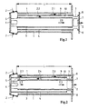
- FIG. 1 is a first embodiment with a Pipe section 1 of a suction device for one not here Shown internal combustion engine shown by the one Airflow according to arrows 2, or arrows 2.0, 2.1 and 2.2 passes through.
- pipe section 1 In pipe section 1 is concentric a first inner tube 3 fixedly attached thereto. Between this first inner tube 3 and the inner wall the pipe section 1 dips an axially displaceable second inner tube 4 a. The second inner tube 4 can be moved axially until it touches a stop plate 5 fits tightly.
- the stop plate 5 serves here also as a holder for the first inner tube 3.
- the first inner tube 3 has at the lower end on the stop plate 5 a number of windows 6 through which are sucked in Air flow into the inside of the first inner tube 3 can not if the second inner tube 4 according to Figure 1 is pushed down.
- the air sucked in flows parallel according to Figure 1 (arrows 2.0, 2.1 and 2.2) through spaces 9 and 10 and through the inner tube 3.
- the movable Inner tube 4 before switching from 6-cylinder 3-cylinder operation the position according to FIG. 1, which allows a parallel flow through the 3 tube spaces.
- the flow path is L
- the flow cross section has the value 3 * A, where A is the area of the cross-section is one of the 3 tube spaces.
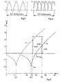
- FIG 3 is the timing of the pulse trains Suction pulse in 3-cylinder operation and in Figure 4 shown in 6-cylinder operation.
- the cycle of the 6-cylinder engine 4 shows the interaction of the Sine waves of the 6th and 12th harmonics of a 720 ° Working cycle, whereby it can be seen that the amplitudes the resulting vibration is significantly smaller than are those of the single pulse.
- it swings 3-cylinder cycle according to Figure 3 almost exclusively with the sine wave of the 3rd harmonic and the amplitude grows beyond the value of the single pulse.
- an engine speed of e.g. 3000 rpm results in the 6-cylinder operation with a disturbing frequency of 150Hz 3-cylinder operation is 75Hz.
- the suction device With the suction device according to the embodiment it is achieved that the acoustically assessed levels are maintained because the 75 Hz tone is rated weaker by 9.5 dB (A) is called the 150Hz tone.
- A 75 Hz tone is rated weaker by 9.5 dB
- One vote is enough to the resonance frequency of 22Hz, which is a um represents the factor 3 reduced frequency.
- the one now occurring 75 Hz tone is attenuated with 20dB (curve 21).
- the Embodiment according to the invention according to FIGS. 1 and 2 thus triples the length of the Damper neck and a third of the cross-sectional area and thus leads to the desired success.
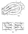
- FIG. 6 shows another preferred exemplary embodiment 11 of the air flow device according to the invention shown through which air flows according to arrows 12.
- Flow channels are between two adjusting devices 13 and 14 15, 16 and 17 arranged, the direction of flow in the flow channels 15, 16 and 17 through Flaps 18 and 19 (not visible here) can be changed.
- the flow channels 15, 16 and 17 preferably exist Made of flexible material, so this air flow device 11 also in places on an assembly (For example, in the engine compartment of a motor vehicle) can be, where not much space for Available.
- the axes 20 and 21 of the flaps 18 and 19 are in the embodiment mechanically coupled to each other, so that usually both flaps are adjusted in parallel with each other are and driven by an actuator same position in the respective adjusting device 13 or take 14.
Landscapes
- Engineering & Computer Science (AREA)
- Chemical & Material Sciences (AREA)
- Combustion & Propulsion (AREA)
- Mechanical Engineering (AREA)
- General Engineering & Computer Science (AREA)
- Characterised By The Charging Evacuation (AREA)
- Exhaust Silencers (AREA)
Claims (13)
- Installation d'aspiration d'air pour un équipement en aval, dans laquelle,caractérisée en ce quedans la zone du chemin d'aspiration, il y a des dispositifs de réglage (13, 14) pour modifier la géométrie d'écoulement de l'air,la section d'ensemble du chemin d'écoulement est subdivisée dans la direction d'écoulement en différents canaux (15, 16, 17) individuels et les dispositifs de réglage (13, 14) commandent les chemins d'écoulement dans les différents canaux (15, 16, 17) pour influencer la longueur active et la section active de l'ensemble de l'installation d'aspiration d'air,en déviant le flux d'air on crée un chemin d'écoulement plus long ou plus court,au moins trois canaux (15, 16, 17) sont prévus dont les extrémités sont raccordées chaque fois à une ouverture intérieure (22-27) du dispositif de réglage (13, 14), etdans chacun des dispositifs de réglage (13, 14) il y a des volets (18, 19) qui, dans une première position de commutation, dirigent le flux d'air (12) de l'entrée du premier dispositif de réglage (13) à travers les canaux (15, 16, 17), selon une direction d'écoulement alternée, successivement vers la sortie du second dispositif de réglage (14), et qui dans une seconde position de commutation, dirigent le flux d'air (12) de l'entrée du premier dispositif de réglage (13) à travers les canaux (15, 16, 17) en parallèle vers la sortie du second dispositif de réglage (14).
- Installation d'aspiration d'air selon la revendication 1,
caractérisée en ce queles volets (18, 19) sont montés pivotants chaque fois sur un axe (20, 21),dans la première position de commutation, les volets (18, 19) assurent le passage en parallèle dans trois canaux et,lorsque les volets (18, 19) occupent la seconde position de commutation, chaque fois deux ouvertures (25, 26 ; 23, 24) des dispositifs de réglage (13, 14) sont fermées vers l'entrée ou vers la sortie mais pour permettre néanmoins un passage d'air entre les ouvertures (25, 26 ; 23, 24) du côté tourné vers les canaux (15, 16, 17). - Installation d'aspiration d'air selon la revendication 2,
caractérisée en ce que
les axes (20, 21) des deux volets (18, 19) sont reliés rigidement et sont entraínés en commun par un actionneur unique. - Installation d'aspiration d'air selon la revendication 2,
caractérisée en ce que
les axes (20, 21) des deux volets (18,19) sont entraínés en commun par un actionneur et sont reliés pour que l'axe entraíné directement ou l'axe (20, 21) mené indirectement comporte une came d'entraínement pour que dans une plage d'angle de rotation définie, seul l'axe directement entraíné (20, 21) règle un volet. - Installation d'aspiration d'air comme dispositif d'aspiration d'un moteur à combustion interne comportant dans la zone du chemin d'aspiration, les moyens pour modifier la géométrie de l'écoulement d'air aspiré,
caractérisée en ce quele chemin d'aspiration comporte un élément de tuyau (1) avec au moins deux tubes intérieurs (3, 4),leur diamètre est choisi pour que le premier (3) et le second tube intérieur (4) puissent coulisser l'un dans l'autre dans l'élément de tuyau (1) etdes moyens sont prévus pour modifier le chemin d'aspiration dans l'élément de tuyau (1), pour permettre à l'air soit de passer en parallèle l'élément de tuyau (1) et les tubes intérieurs (3, 4), soit de passer dans des directions alternées, à travers les intervalles (9, 10) branchés en série de l'élément de tuyau (1) et des tubes intérieurs (3, 4), ainsi qu'à travers le tube (3) le plus à l'intérieur. - Installation d'aspiration d'air selon la revendication 5,
caractérisée en ce quele premier tube intérieur (3) est accroché solidairement dans l'élément de tube (1), au moins une fenêtre (6) étant prévue pour l'entrée de l'air dans le premier tuyau intérieur (3) et,le second tuyau intérieur (4) est coulissant dans le tube (1) avec des ouvertures (7) et des éléments d'étanchéité (8) par-dessus le premier tube intérieur (3), pour qu'en position de repos, l'air puisse passer en parallèle à travers les intervalles (9, 10) et le premier tube intérieur (3), et qu'en position de commutation, les chemins d'aspiration soient branchés en série :dans la direction d'aspiration, l'air passe dans un premier intervalle (9) entre l'élément de tuyau (1) et le second tube intérieur (4),à l'extrémité de cet intervalle (9), l'air passe dans la direction opposée à travers l'intervalle (10) entre le premier et le second tube intérieur (3, 4) et,à l'extrémité du second intervalle (10), l'air arrive dans le premier tube intérieur (3) et sort de l'élément de tuyau (1) dans la direction d'aspiration (2). - Installation d'aspiration d'air selon la revendication 6,
caractérisée en ce qu'en position de commutation, à travers au moins une fenêtre (6) dans le premier tube intérieur (3), on a un chemin de communication entre l'intervalle (10) et le canal de sortie par l'extrémité amont du second tube intérieur (4),le second tube intérieur (4) comporte au moins une fenêtre (7) pour relier le premier intervalle (9) et le second intervalle (10) et,à l'autre extrémité du second tube intérieur (4), coulissant, il est prévu un joint (8) pour assurer l'étanchéité des deux intervalles (9, 10) vers l'extérieur. - Installation d'aspiration d'air selon la revendication 6 ou 7
caractérisée en ce qu'
une plaque de butée (5), au niveau de laquelle il y a des ouvertures pour l'air (2) dans le chemin d'aspiration, forme en outre la butée pour une extrémité du second tube intérieur (4), coulissant en position de commutation, et le premier tube intérieur (3), fixe, est fixé sur cette plaque de butée. - Installation d'aspiration d'air selon l'une des revendications 6 à 8,
caractérisée en ce que
le second tube intérieur (4) est coulissant sur des éléments de support prévus à l'extérieur du premier tube intérieur fixe (3) . - Installation d'aspiration d'air selon l'une des revendications 6 à 9,
caractérisée en ce que
le second tube intérieur (4) est coulissant contre des éléments de support prévus à l'intérieur sur l'élément de support (1). - Installation d'aspiration d'air selon l'une des revendications 6 à 10,
caractérisée en ce que
les impulsions de commutation nécessaires au glissement du second tube intérieur (4) sont générées par un système hydraulique d'un véhicule automobile en fonction du nombre de cylindres actifs du moteur à combustion interne. - Installation d'aspiration d'air selon l'une des revendications 1 à 4,
caractérisée en ce que
l'installation est un dispositif d'aspiration d'un moteur à combustion interne d'un véhicule automobile. - Installation d'aspiration d'air selon la revendication 12,
caractérisée en ce que
le véhicule automobile comporte un dispositif pour couper une partie des cylindres du moteur à combustion interne.
Applications Claiming Priority (5)
| Application Number | Priority Date | Filing Date | Title |
|---|---|---|---|
| DE19622235 | 1996-06-03 | ||
| DE19622235A DE19622235C2 (de) | 1996-06-03 | 1996-06-03 | Ansaugvorrichtung für einen Verbrennungsmotor |
| DE19631036 | 1996-08-01 | ||
| DE19631036 | 1996-08-01 | ||
| PCT/EP1997/002384 WO1997046797A1 (fr) | 1996-06-03 | 1997-05-09 | Dispositif de circulation d'air |
Publications (2)
| Publication Number | Publication Date |
|---|---|
| EP0902862A1 EP0902862A1 (fr) | 1999-03-24 |
| EP0902862B1 true EP0902862B1 (fr) | 2000-11-15 |
Family
ID=26026260
Family Applications (1)
| Application Number | Title | Priority Date | Filing Date |
|---|---|---|---|
| EP97923040A Expired - Lifetime EP0902862B1 (fr) | 1996-06-03 | 1997-05-09 | Dispositif de circulation d'air |
Country Status (7)
| Country | Link |
|---|---|
| US (1) | US6148782A (fr) |
| EP (1) | EP0902862B1 (fr) |
| JP (1) | JP2000515214A (fr) |
| BR (1) | BR9709517A (fr) |
| CA (1) | CA2257510A1 (fr) |
| DE (1) | DE59702642D1 (fr) |
| WO (1) | WO1997046797A1 (fr) |
Cited By (1)
| Publication number | Priority date | Publication date | Assignee | Title |
|---|---|---|---|---|
| DE102015221249A1 (de) * | 2015-10-30 | 2017-05-04 | Mahle International Gmbh | Ansaugluftführung für eine Brennkraftmaschine |
Families Citing this family (15)
| Publication number | Priority date | Publication date | Assignee | Title |
|---|---|---|---|---|
| JP2000337255A (ja) | 1999-05-26 | 2000-12-05 | Toyota Autom Loom Works Ltd | 減衰装置及び圧縮機の吸入構造 |
| JP2001059458A (ja) * | 1999-06-16 | 2001-03-06 | Aichi Mach Ind Co Ltd | 内燃機関用吸気マニホールド |
| US7263961B2 (en) * | 2003-10-01 | 2007-09-04 | Leo Now | Gas directing system and method |
| US20050279320A1 (en) * | 2004-06-18 | 2005-12-22 | Roberts Alexander J | Method and means for improved efficiency of cylinder deactivation (DODTM) engines |
| DE102005029760A1 (de) * | 2005-05-23 | 2006-11-30 | Bitzer Kühlmaschinenbau Gmbh | Kältemittelverdichter |
| US7614379B2 (en) * | 2005-05-23 | 2009-11-10 | Leo Now | Air horn for efficient fluid intake |
| US7401590B2 (en) * | 2006-10-09 | 2008-07-22 | Harley-Davidson Motor Company Group, Inc. | Active air intake for an engine |
| US7556019B2 (en) * | 2006-12-15 | 2009-07-07 | Briggs And Stratton Corporation | Intake manifold regulators for internal combustion engines |
| KR100957142B1 (ko) * | 2007-07-30 | 2010-05-11 | 현대자동차주식회사 | 에너 클리너 흡기 덕트 |
| EP2030615A3 (fr) * | 2007-08-13 | 2009-12-02 | ELFORD, Howard L. | Inhibiteurs de la ribonucleotide reductase pour leur utilisation dans le traitement ou la prévention de maladies neuro-inflammatoires ou auto-immunes |
| US8375915B1 (en) | 2009-02-25 | 2013-02-19 | Leo Now | Gas directing system and method |
| US7975669B2 (en) * | 2009-07-28 | 2011-07-12 | GM Global Technology Operations LLC | Apparatus and method for throttle control of internal combustion engines |
| DE102017118643A1 (de) * | 2017-08-16 | 2019-02-21 | Franz Haimer Maschinenbau Kg | Vorrichtung zur Kühlung eines Schrumpffutters |
| DE102020122027B4 (de) * | 2020-08-24 | 2023-05-04 | Mann+Hummel Gmbh | Schalldämpfer und Filtersystem |
| USD1068510S1 (en) * | 2023-08-21 | 2025-04-01 | Elevation Lab, Inc. | Tracker housing |
Family Cites Families (10)
| Publication number | Priority date | Publication date | Assignee | Title |
|---|---|---|---|---|
| US2835235A (en) * | 1955-06-20 | 1958-05-20 | Daimler Benz Ag | Intake manifold for internal combustion engines |
| JPS5818533A (ja) * | 1981-07-23 | 1983-02-03 | Nissan Motor Co Ltd | 気筒数制御エンジン |
| DE3814836A1 (de) * | 1987-05-26 | 1988-12-08 | Volkswagen Ag | Laengenveraenderbares saugrohr fuer eine brennkraftmaschine |
| JPS6424114A (en) * | 1987-07-16 | 1989-01-26 | Nippon Denso Co | Intake device for internal-combustion engine |
| JPS6424115A (en) * | 1987-07-17 | 1989-01-26 | Nippon Denso Co | Intake device for internal-combustion engine |
| GB2221954B (en) * | 1988-08-16 | 1992-07-08 | Austin Rover Group | An internal combustion engine inlet manifold |
| DE4041200C2 (de) * | 1990-12-21 | 1993-11-04 | Porsche Ag | Luftansauganlage fuer eine brennkraftmaschine |
| JP3191487B2 (ja) * | 1993-05-25 | 2001-07-23 | いすゞ自動車株式会社 | 多気筒内燃機関の吸気装置 |
| DE4333053A1 (de) * | 1993-09-29 | 1995-03-30 | Opel Adam Ag | Brennkraftmaschine mit einem Luftansaugsystem |
| DE19501411A1 (de) * | 1995-01-19 | 1996-07-25 | Mann & Hummel Filter | Ansaugvorrichtung für einen Verbrennungsmotor |
-
1997
- 1997-05-09 BR BR9709517A patent/BR9709517A/pt not_active Application Discontinuation
- 1997-05-09 EP EP97923040A patent/EP0902862B1/fr not_active Expired - Lifetime
- 1997-05-09 US US09/194,763 patent/US6148782A/en not_active Expired - Fee Related
- 1997-05-09 CA CA002257510A patent/CA2257510A1/fr not_active Abandoned
- 1997-05-09 WO PCT/EP1997/002384 patent/WO1997046797A1/fr not_active Ceased
- 1997-05-09 JP JP10500127A patent/JP2000515214A/ja active Pending
- 1997-05-09 DE DE59702642T patent/DE59702642D1/de not_active Expired - Fee Related
Cited By (1)
| Publication number | Priority date | Publication date | Assignee | Title |
|---|---|---|---|---|
| DE102015221249A1 (de) * | 2015-10-30 | 2017-05-04 | Mahle International Gmbh | Ansaugluftführung für eine Brennkraftmaschine |
Also Published As
| Publication number | Publication date |
|---|---|
| DE59702642D1 (de) | 2000-12-21 |
| JP2000515214A (ja) | 2000-11-14 |
| BR9709517A (pt) | 1999-08-10 |
| CA2257510A1 (fr) | 1997-12-11 |
| EP0902862A1 (fr) | 1999-03-24 |
| US6148782A (en) | 2000-11-21 |
| WO1997046797A1 (fr) | 1997-12-11 |
Similar Documents
| Publication | Publication Date | Title |
|---|---|---|
| EP0902862B1 (fr) | Dispositif de circulation d'air | |
| DE102007043147B4 (de) | Kontinuierlich variabel abgestimmter Resonator | |
| EP1760279B1 (fr) | Silencieux pour un système d'échappement | |
| DE102005022824B4 (de) | Elektronisch gesteuerter variabler Zweikammer-Resonator | |
| DE102004007717B4 (de) | Helmholtz-Resonator | |
| DE19720410B4 (de) | Schalldämpfer | |
| DE602004000518T2 (de) | Schalldämpfer mit einem variablen Einstellsystem und Verfahren zum betreiben eines Schalldämpfers | |
| DE69702447T2 (de) | Abgasvorrichtung für brennkraftmaschinen und fahrzeug mit dieser vorrichtung | |
| DE69102199T2 (de) | Dynamisch abgestimmtes Auspuffsystem. | |
| EP0897468B1 (fr) | Dispositif d'admission pour moteur a combustion interne | |
| DE69807736T2 (de) | Vorrichtung und verfahren für schalldämpfungseinheiten | |
| DE102015211460A1 (de) | Abgasanlage | |
| DE10042012A1 (de) | Vorrichtung zur Geräuschgestaltung bei einem Kraftfahrzeug | |
| DE10205703A1 (de) | Pneumatisch gesteuerter Dämpfer | |
| EP1012458A1 (fr) | Systeme d'aspiration pour moteur a combustion interne | |
| DE10231238B4 (de) | Geräuschdämpfungsvorrichtung | |
| DE102017126761A1 (de) | Vakuumbetätigter mehrfrequenz-viertelwellenresonator für einen verbrennungsmotor | |
| DE102007026416B4 (de) | Vorrichtung zur Beeinflussung des Ansauggeräusches einer Brennkraftmaschine | |
| EP1321639A2 (fr) | Dispositif silencieux | |
| DE19520157A1 (de) | Schalldämpfer für Kraftfahrzeuge | |
| DE19622235C2 (de) | Ansaugvorrichtung für einen Verbrennungsmotor | |
| DE10332640B3 (de) | Luftansaugkanalsystem für Verbrennungskraftmaschinen | |
| DE102011017226A1 (de) | Abgasanlage mit einer Abgasrückführundgeinrichtungund Verfahren zum Betreiben einer solchen Abgasanlage | |
| DE10354699B4 (de) | Abgasschalldämpfer für Brennkraftmaschinen | |
| DE19638304A1 (de) | Schalldämpfer |
Legal Events
| Date | Code | Title | Description |
|---|---|---|---|
| PUAI | Public reference made under article 153(3) epc to a published international application that has entered the european phase |
Free format text: ORIGINAL CODE: 0009012 |
|
| 17P | Request for examination filed |
Effective date: 19981027 |
|
| AK | Designated contracting states |
Kind code of ref document: A1 Designated state(s): DE ES FR GB IT |
|
| 17Q | First examination report despatched |
Effective date: 19990325 |
|
| GRAG | Despatch of communication of intention to grant |
Free format text: ORIGINAL CODE: EPIDOS AGRA |
|
| GRAG | Despatch of communication of intention to grant |
Free format text: ORIGINAL CODE: EPIDOS AGRA |
|
| GRAH | Despatch of communication of intention to grant a patent |
Free format text: ORIGINAL CODE: EPIDOS IGRA |
|
| GRAH | Despatch of communication of intention to grant a patent |
Free format text: ORIGINAL CODE: EPIDOS IGRA |
|
| GRAA | (expected) grant |
Free format text: ORIGINAL CODE: 0009210 |
|
| AK | Designated contracting states |
Kind code of ref document: B1 Designated state(s): DE ES FR GB IT |
|
| PG25 | Lapsed in a contracting state [announced via postgrant information from national office to epo] |
Ref country code: IT Free format text: LAPSE BECAUSE OF FAILURE TO SUBMIT A TRANSLATION OF THE DESCRIPTION OR TO PAY THE FEE WITHIN THE PRE;WARNING: LAPSES OF ITALIAN PATENTS WITH EFFECTIVE DATE BEFORE 2007 MAY HAVE OCCURRED AT ANY TIME BEFORE 2007. THE CORRECT EFFECTIVE DATE MAY BE DIFFERENT FROM THE ONE RECORDED.SCRIBED TIME-LIMIT Effective date: 20001115 Ref country code: GB Free format text: LAPSE BECAUSE OF FAILURE TO SUBMIT A TRANSLATION OF THE DESCRIPTION OR TO PAY THE FEE WITHIN THE PRESCRIBED TIME-LIMIT Effective date: 20001115 Ref country code: FR Free format text: LAPSE BECAUSE OF FAILURE TO SUBMIT A TRANSLATION OF THE DESCRIPTION OR TO PAY THE FEE WITHIN THE PRESCRIBED TIME-LIMIT Effective date: 20001115 Ref country code: ES Free format text: THE PATENT HAS BEEN ANNULLED BY A DECISION OF A NATIONAL AUTHORITY Effective date: 20001115 |
|
| REF | Corresponds to: |
Ref document number: 59702642 Country of ref document: DE Date of ref document: 20001221 |
|
| EN | Fr: translation not filed | ||
| PGFP | Annual fee paid to national office [announced via postgrant information from national office to epo] |
Ref country code: DE Payment date: 20010509 Year of fee payment: 5 |
|
| GBV | Gb: ep patent (uk) treated as always having been void in accordance with gb section 77(7)/1977 [no translation filed] |
Effective date: 20001115 |
|
| PLBE | No opposition filed within time limit |
Free format text: ORIGINAL CODE: 0009261 |
|
| STAA | Information on the status of an ep patent application or granted ep patent |
Free format text: STATUS: NO OPPOSITION FILED WITHIN TIME LIMIT |
|
| 26N | No opposition filed | ||
| PG25 | Lapsed in a contracting state [announced via postgrant information from national office to epo] |
Ref country code: DE Free format text: LAPSE BECAUSE OF NON-PAYMENT OF DUE FEES Effective date: 20021203 |