EP0903014B1 - Commutateur de proximite a decouplage mecanique de broches de contact et de dispositif enfichable - Google Patents
Commutateur de proximite a decouplage mecanique de broches de contact et de dispositif enfichable Download PDFInfo
- Publication number
- EP0903014B1 EP0903014B1 EP97925874A EP97925874A EP0903014B1 EP 0903014 B1 EP0903014 B1 EP 0903014B1 EP 97925874 A EP97925874 A EP 97925874A EP 97925874 A EP97925874 A EP 97925874A EP 0903014 B1 EP0903014 B1 EP 0903014B1
- Authority
- EP
- European Patent Office
- Prior art keywords
- housing
- proximity switch
- casting compound
- insert
- accordance
- Prior art date
- Legal status (The legal status is an assumption and is not a legal conclusion. Google has not performed a legal analysis and makes no representation as to the accuracy of the status listed.)
- Expired - Lifetime
Links
Images


Classifications
-
- H—ELECTRICITY
- H03—ELECTRONIC CIRCUITRY
- H03K—PULSE TECHNIQUE
- H03K17/00—Electronic switching or gating, i.e. not by contact-making and –breaking
- H03K17/94—Electronic switching or gating, i.e. not by contact-making and –breaking characterised by the way in which the control signals are generated
- H03K17/945—Proximity switches
- H03K17/95—Proximity switches using a magnetic detector
- H03K17/9505—Constructional details
-
- H—ELECTRICITY
- H05—ELECTRIC TECHNIQUES NOT OTHERWISE PROVIDED FOR
- H05K—PRINTED CIRCUITS; CASINGS OR CONSTRUCTIONAL DETAILS OF ELECTRIC APPARATUS; MANUFACTURE OF ASSEMBLAGES OF ELECTRICAL COMPONENTS
- H05K1/00—Printed circuits
- H05K1/18—Printed circuits structurally associated with non-printed electric components
- H05K1/182—Printed circuits structurally associated with non-printed electric components associated with components mounted in printed circuit boards [PCB], e.g. insert-mounted components [IMC]
-
- H—ELECTRICITY
- H05—ELECTRIC TECHNIQUES NOT OTHERWISE PROVIDED FOR
- H05K—PRINTED CIRCUITS; CASINGS OR CONSTRUCTIONAL DETAILS OF ELECTRIC APPARATUS; MANUFACTURE OF ASSEMBLAGES OF ELECTRICAL COMPONENTS
- H05K3/00—Apparatus or processes for manufacturing printed circuits
- H05K3/40—Forming printed elements for providing electric connections to or between printed circuits
- H05K3/403—Edge contacts; Windows or holes in the substrate having plural connections on the walls thereof
Definitions
- the invention relates to a proximity switch, with a housing with a sensor element, e.g. a bowl core with a sensor coil, with a circuit board, which in a potting compound embedded in the housing and on the one hand with the sensor element and on the other hand with electrical pins or is mechanically connected and to a method for producing a proximity switch.
- a sensor element e.g. a bowl core with a sensor coil
- a circuit board which in a potting compound embedded in the housing and on the one hand with the sensor element and on the other hand with electrical pins or is mechanically connected and to a method for producing a proximity switch.
- a generic proximity switch is e.g. from the German Utility model DE 92 00 772 U1 known. With this one the sleeve-shaped housing at the level of a centrally arranged Light emitting diode provided with several holes to the switching state of the proximity switch visible on all sides close. As a light guide from the LED to the holes A transparent plug insert serves up to the holes are enough. The plug insert is with connection pins firmly connected, the ends of which directly after cranking the circuit board are electrically connected. The Plug pins with cranked ends can be attached directly to the PCB must be soldered.
- the invention has for its object a proximity switch of the above kind to create the one without transfer of forces on the circuit board on the sensor element is mountable. Furthermore, it is an object of the invention to specify the corresponding manufacturing process.
- the object is achieved in that the connecting pins, apart of the sealing compound, only by a direct one mechanical connection with the circuit board are kept and that a connector insert integrated into the housing connects the pins surrounds without performing a support function for them.
- circuit board together with the connection pins and with the sensor element is designed as a modular switch insert that in the housing, apart from the potting compound, only supported on the sensor element.
- This version proves proved to be particularly easy to assemble because of the switch insert can be easily prefabricated and then used as a structural unit is much easier.
- the plug insert for Guidance of the soldering pins during assembly guiding means having.
- This technical measure also makes it easier Assembly.
- the guide means are expediently designed as noses with holes with a compared to the thickness of the pins larger bore diameter executed.
- Plug insert At least partially made of transparent material.
- the plug insert is circumferential Seal that has a gap to the housing in such a way seals that they have an outflow of potting compound over Openings for status display prevented.
- a cylindrical housing, one end opening through a Cap is covered, is poured out with casting compound to the extent that a defined space between one for switching status display serving opening in the housing remains free, in the uncured casting compound becomes uniform from a printed circuit board, connecting pins and a sensor element, e.g. a shell core with a sensor coil, assembled Switch insert introduced, the potting compound is partially displaced towards the opening, one at its Bottom partially open connector insert is in the housing introduced with displacement of potting compound, at least this partly the space between the plug insert and fills the inner wall of the housing.
- a sensor element e.g. a shell core with a sensor coil, assembled Switch insert
- the process is advantageously improved if the Switch insert after insertion into the uncured sealing compound only with the sensor element on the cap supports its own weight. As a result, no further possibly destructive forces on the Sensor element, e.g. the bowl core.
- the proximity switch according to the invention in particular an inductive one Proximity switch, includes one shown in FIG 1 Switching insert 1.
- This is essentially made up of a Printed circuit board 2, a shell core 3 with a sensor coil as Sensor element on one side and solder pins 4 and one LED 5 assembled on the other side.
- FIG. 2 shows a cylindrical housing of an inventive Proximity switch, one end opening through a cap 7th is tightly closed.
- the housing 6 is defined except for one Clearance to an opening 8 for a switching status display filled with a potting compound 9.
- the switch insert 1 according to FIG. 1 is in the sealing compound 9 is shown embedded, the shell core 3 is supported on the cap 7 and only after the casting compound has hardened is additionally held by this.
- the switching insert 1 in the potting compound 9 this displaced towards the opening 8 as indicated in FIG 3 is.
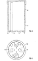
- FIG 4 shows the connection area of the housing 6, the change compared to FIG 3 is that additionally a plug insert in the cylindrical housing 6 10 is pushed.
- 5 has a circumferential one Seal in the form of a scraper rib 11, which the outflow of potting compound 9 through the opening 8 for the status display prevented.
- the plug insert 10 is on its underside with four lugs 12 with half bores 13 for guiding the connecting pins 4 provided. The four lugs 12 secure in connection with the rising potting compound 9 in the interior of the connector the plug insert 10 against tensile and torsional forces.
- the light emitting diode 5 is outside the potting compound 9, so that it does not necessarily have to be transparent. It is only one partially transparent towards the opening 8 Plug insert 10 required to display the switching status to ensure by the LED 5.
- Proximity switch is in its individual steps 1 to 4.
- the one assembled Switch insert 1 according to FIG 1 is in the potting compound 9 filled cylindrical housing 6 introduced. After introduction the switch insert 1 over its shell core 3 the cap 7 held in the housing 6 as shown in FIG 3 is.
- the interface of the sealing compound 9 rises due to the Displacement through the switch insert 1 towards the opening 8. 5 and 6 in the cylindrical housing 6 is inserted, with the connecting pins 4 out through half bores 13 on the plug insert 10 become.
- the scraper rib 11 also urges potting compound 9 the inner wall of the housing 6 back and thus prevents the Potting compound 9 emerges through opening 8.
- the assembly of the proximity switch is characterized by that there are no forces on the electrical circuit, i.e. about the circuit board 2 on the shell core 3, are transferred. This is achieved in that the pins 4 are not through the plug insert 10 but through the printed circuit board 2 being held. Decoupling of the mechanical Connection between the plug insert 10 and the connecting pins 4 reached. Another major advantage is there in that now only one in the manufacturing process one-time potting is required.
Landscapes
- Switches That Are Operated By Magnetic Or Electric Fields (AREA)
Claims (9)
- Commutateur de proximité, notamment commutateur inductif de proximité, comprenant un boítier (6), un élément (3) formant capteur, par exemple un noyau en forme de coquille ayant une bobine de capteur, une plaquette (2) à circuit imprimé qui est enrobée dans le boítier (6) dans une composition (9) de scellement et qui est reliée électriquement et mécaniquement d'une part à l'élément (3) formant capteur et d'autre part à des broches (4) de raccordement, les broches (4) de raccordement étant maintenues indépendamment de la composition (9) de scellement seulement par une liaison mécanique directe avec la plaquette (2) à circuit imprimé et en ce qu'un dispositif enfichable intégré dans le boítier (6) entoure les broches (4) de raccordement sans exercer pour celles-ci une fonction de maintien.
- Commutateur de proximité suivant la revendication 1, caractérisé en ce que la plaquette (2) à circuit imprimé est exécutée ensemble avec les broches (4) de raccordement à l'élément (3) formant capteur sous la forme d'un insert (1) formant une unité de construction qui est soutenue dans le boítier (6), indépendamment de la composition (9) de scellement, seulement par l'élément (3) formant capteur.
- Commutateur de proximité suivant la revendication 1 ou 2, caractérisé en ce que le dispositif (10) enfichable comporte des moyens (12, 13) de guidage servant à guider les broches (4) de raccordement pendant le montage.
- Commutateur de proximité suivant la revendication 3, caractérisé en ce que les moyens de guidage sont constitués en becs (12) ayant des trous (13) avec un diamètre des trous plus grand que l'épaisseur des broches (4) de raccordement.
- Commutateur de proximité suivant l'une des revendications précédentes, caractérisé en ce que l'incorporation de l'insert dans le boítier (6) s'effectue dans une composition (9) de scellement ménagée par une seule coulée.
- Commutateur de proximité suivant l'une des revendications précédentes, caractérisé en ce que le dispositif (10) enfichable est au moins partiellement en une matière transparente.
- Commutateur de proximité suivant l'une des revendications précédentes, caractérisé en ce que le dispositif (10) enfichable comporte une garniture (11) d'étanchéité qui fait le tour, qui rend étanche un intervalle vis à vis du boítier (6) de manière à empêcher toute sortie de la composition (9) de scellement par des ouvertures (8) destinées à indiquer un état.
- Procédé de fabrication d'un commutateur de proximité suivant l'une des revendications 1 à 7, caractérisé par les stades suivants :a) on coule un boítier (6) cylindrique, dont une ouverture d'extrémité est recouverte d'un chapeau (7), d'une composition (9) de scellement jusqu'à ce qu'il subsiste dans le boítier (6) un intervalle défini entre une ouverture (8) servant à indiquer l'état de commutation,b) dans la composition (9) de scellement qui n'est pas encore durcie est introduit un insert (1) constitué en une unité de construction d'une plaquette (2) à circuit imprimé, de broches (4) de raccordement ainsi que d'un élément (3) formant capteur, par exemple d'un noyau en forme de coquille, ayant une bobine de capteur, la composition (9) de scellement étant refoulée en partie vers l'ouverture (8) etc) un dispositif (10) enfichable ouvert partiellement sur son fond est introduit dans le boítier (6) en refoulant de la composition (9) de scellement, celle-ci remplissant au moins partiellement l'intervalle compris entre le dispositif (10) enfichable et la paroi intérieure du boítier (6).
- Procédé suivant la revendication 8, caractérisé en ce que l'insert (1) est soutenu après introduction dans la composition (9) de scellement qui n'a pas encore durci sur le chapeau (7) par l'élément (3) formant capteur.
Applications Claiming Priority (3)
| Application Number | Priority Date | Filing Date | Title |
|---|---|---|---|
| DE19622445A DE19622445C1 (de) | 1996-06-05 | 1996-06-05 | Näherungsschalter mit mechanischer Entkopplung von Anschlußstiften und Steckereinsatz |
| DE19622445 | 1996-06-05 | ||
| PCT/DE1997/001066 WO1997047087A1 (fr) | 1996-06-05 | 1997-05-26 | Commutateur de proximite a decouplage mecanique de broches de contact et de dispositif enfichable |
Publications (2)
| Publication Number | Publication Date |
|---|---|
| EP0903014A1 EP0903014A1 (fr) | 1999-03-24 |
| EP0903014B1 true EP0903014B1 (fr) | 2001-08-08 |
Family
ID=7796137
Family Applications (1)
| Application Number | Title | Priority Date | Filing Date |
|---|---|---|---|
| EP97925874A Expired - Lifetime EP0903014B1 (fr) | 1996-06-05 | 1997-05-26 | Commutateur de proximite a decouplage mecanique de broches de contact et de dispositif enfichable |
Country Status (4)
| Country | Link |
|---|---|
| US (1) | US6229420B1 (fr) |
| EP (1) | EP0903014B1 (fr) |
| DE (2) | DE19622445C1 (fr) |
| WO (1) | WO1997047087A1 (fr) |
Families Citing this family (12)
| Publication number | Priority date | Publication date | Assignee | Title |
|---|---|---|---|---|
| US6433445B1 (en) * | 2000-01-06 | 2002-08-13 | International Business Machines Corporation | Active mating connector |
| DE10000350A1 (de) * | 2000-01-07 | 2001-07-12 | Kostal Leopold Gmbh & Co Kg | Sensormodul für ein elektrisches Steckergehäuse |
| DE10013218C2 (de) * | 2000-03-17 | 2003-06-05 | Balluff Gmbh | Verfahren zur Herstellung eines Positionssensors und Positionssensor |
| DE10109442B4 (de) * | 2001-02-27 | 2007-09-06 | Ifm Electronic Gmbh | Verfahren zur Herstellung eines Näherungsschalters und Näherungsschalter |
| DE20209067U1 (de) | 2002-06-11 | 2003-10-16 | Weidmüller Interface GmbH & Co., 32760 Detmold | Anschlußvorrichtung mit wenigstens einem rohrartigen Grundkörper |
| JP3844073B2 (ja) * | 2002-09-13 | 2006-11-08 | オムロン株式会社 | 近接センサ |
| US7268688B2 (en) * | 2005-08-31 | 2007-09-11 | Idx, Inc. | Shielded RFID transceiver with illuminated sensing surface |
| CN101064403B (zh) * | 2006-04-27 | 2010-08-11 | 光阳工业股份有限公司 | Led定位装置 |
| FR2913808B1 (fr) * | 2007-03-16 | 2009-04-24 | Siemens Vdo Automotive Sas | Procede d'entancheisation d'un capteur electronique de forme complexe par injection basse pression de resine reactive |
| US8054184B2 (en) * | 2008-07-31 | 2011-11-08 | Intuitive Surgical Operations, Inc. | Identification of surgical instrument attached to surgical robot |
| US9211161B2 (en) * | 2013-03-06 | 2015-12-15 | DePuy Synthes Products, Inc. | Apparatus and methods for associating medical probes with connection ports |
| DE102015121434A1 (de) * | 2015-12-09 | 2017-06-14 | Huf Hülsbeck & Fürst Gmbh & Co. Kg | Kameraeinheit mit einer Reinigungsvorrichtung |
Family Cites Families (8)
| Publication number | Priority date | Publication date | Assignee | Title |
|---|---|---|---|---|
| DE9200772U1 (de) * | 1992-01-23 | 1992-03-05 | Siemens AG, 80333 München | Näherungsschalter mit Schaltzustandsanzeige |
| DE9200770U1 (de) * | 1992-01-23 | 1992-03-05 | Siemens AG, 8000 München | Näherungsschalter mit Anpassung an Sensorgröße |
| DE9302714U1 (de) * | 1993-02-25 | 1993-04-15 | Pulsotronic Merten GmbH & Co KG, 51643 Gummersbach | Näherungsschalter mit einem hülsenartigen Gehäuse |
| US5508611A (en) * | 1994-04-25 | 1996-04-16 | General Motors Corporation | Ultrathin magnetoresistive sensor package |
| US5498651A (en) * | 1995-06-19 | 1996-03-12 | General Electric Company | Method for polymerizing macrocyclic polyester oligomers |
| DE19544815C1 (de) * | 1995-12-01 | 1997-04-10 | Balluff Gebhard Gmbh & Co | Sensor und Verfahren zu seiner Herstellung |
| US5803604A (en) * | 1996-09-30 | 1998-09-08 | Exergen Corporation | Thermocouple transmitter |
| US5878824A (en) * | 1996-11-27 | 1999-03-09 | Digital Control Incorporated | Boring tool or other device including thermal protection for an electronic component assembly and method |
-
1996
- 1996-06-05 DE DE19622445A patent/DE19622445C1/de not_active Expired - Fee Related
-
1997
- 1997-05-26 EP EP97925874A patent/EP0903014B1/fr not_active Expired - Lifetime
- 1997-05-26 WO PCT/DE1997/001066 patent/WO1997047087A1/fr not_active Ceased
- 1997-05-26 DE DE59704250T patent/DE59704250D1/de not_active Expired - Lifetime
- 1997-05-26 US US09/194,214 patent/US6229420B1/en not_active Expired - Fee Related
Also Published As
| Publication number | Publication date |
|---|---|
| WO1997047087A1 (fr) | 1997-12-11 |
| US6229420B1 (en) | 2001-05-08 |
| DE59704250D1 (de) | 2001-09-13 |
| EP0903014A1 (fr) | 1999-03-24 |
| DE19622445C1 (de) | 1997-07-24 |
Similar Documents
| Publication | Publication Date | Title |
|---|---|---|
| EP2320092B1 (fr) | Unité de pompage | |
| EP1947343B1 (fr) | Unité de pompage | |
| DE4023792C2 (de) | Verfahren zur Herstellung eines Näherungsschalters mit Befestigungshülse | |
| DE4328089C2 (de) | Verfahren zum Herstellen einer Zündspuleneinheit für einen Verbrennungsmotor sowie nach diesem Verfahren hergestellte Zündspuleneinheit | |
| DE19622445C1 (de) | Näherungsschalter mit mechanischer Entkopplung von Anschlußstiften und Steckereinsatz | |
| DE10338377A1 (de) | Magnetventil mit Anschlusskasten | |
| EP1806564A2 (fr) | Finition de boîtier pour boîtier électronique et procédé pour sa fabrication | |
| DE112007001716T5 (de) | Automatikgetriebesteuereinheit und Automatikgetriebe mit diesem | |
| DE10013218A1 (de) | Verfahren zur Herstellung eines Positionssensors und Positionssensor | |
| EP1133012B1 (fr) | Boítier de bornes enfichable | |
| EP1199913A2 (fr) | Méthode de fabrication d'unités comprenant une feuille de circuit et un boítier de support | |
| DE20307111U1 (de) | Komponententräger | |
| EP1511130B1 (fr) | Lampe à décharge haute pression | |
| DE9012881U1 (de) | Anordnung eines Varistors in einem Gehäuse | |
| DE602004004743T2 (de) | Verbindung eines Elektromagnetventiles mit einem Leiterrahmen | |
| EP1216374A2 (fr) | Ensemble servant a assurer la mise en contact electrique d'une soupape | |
| DE2618994B2 (de) | Verfahren zur Herstellung von von Kontaktblechstücken durchragten Unterteilen bzw. Sockeln für elektromagnetische Relais | |
| DE4432468C1 (de) | Näherungsschalter und ein Verfahren zu dessen Herstellung | |
| DE102007042449A1 (de) | Integriertes Sensormodul | |
| DE4405578B4 (de) | Elektronische Baueinheit | |
| DE102007036070A1 (de) | Aktuatoranordnung für eine Bremseinheit einer Fahrzeugbremsanlage mit integrierter Ansteuerungselektronik und Bremseinheit | |
| DE3305855A1 (de) | Vorrichtung zur erfassung der fuellstandshoehe einer fluessigkeit | |
| DE9400585U1 (de) | Abgedichteter elektrischer Stecker | |
| DE102019214606A1 (de) | Elektronikmodul | |
| DE4405439A1 (de) | Elektrische Schaltungsanordnung und Herstellverfahren dafür |
Legal Events
| Date | Code | Title | Description |
|---|---|---|---|
| PUAI | Public reference made under article 153(3) epc to a published international application that has entered the european phase |
Free format text: ORIGINAL CODE: 0009012 |
|
| 17P | Request for examination filed |
Effective date: 19981117 |
|
| AK | Designated contracting states |
Kind code of ref document: A1 Designated state(s): CH DE FR GB LI |
|
| RTI1 | Title (correction) |
Free format text: PROXIMITY SWITCH WITH MECHANICAL DECOUPLING OF TERMINAL PINS AND PLUG-IN UNIT |
|
| GRAG | Despatch of communication of intention to grant |
Free format text: ORIGINAL CODE: EPIDOS AGRA |
|
| GRAG | Despatch of communication of intention to grant |
Free format text: ORIGINAL CODE: EPIDOS AGRA |
|
| GRAH | Despatch of communication of intention to grant a patent |
Free format text: ORIGINAL CODE: EPIDOS IGRA |
|
| 17Q | First examination report despatched |
Effective date: 20001213 |
|
| GRAH | Despatch of communication of intention to grant a patent |
Free format text: ORIGINAL CODE: EPIDOS IGRA |
|
| GRAA | (expected) grant |
Free format text: ORIGINAL CODE: 0009210 |
|
| AK | Designated contracting states |
Kind code of ref document: B1 Designated state(s): CH DE FR GB LI |
|
| REG | Reference to a national code |
Ref country code: CH Ref legal event code: NV Representative=s name: SIEMENS SCHWEIZ AG Ref country code: CH Ref legal event code: EP |
|
| REF | Corresponds to: |
Ref document number: 59704250 Country of ref document: DE Date of ref document: 20010913 |
|
| GBT | Gb: translation of ep patent filed (gb section 77(6)(a)/1977) |
Effective date: 20011001 |
|
| REG | Reference to a national code |
Ref country code: GB Ref legal event code: IF02 |
|
| ET | Fr: translation filed | ||
| PLBE | No opposition filed within time limit |
Free format text: ORIGINAL CODE: 0009261 |
|
| STAA | Information on the status of an ep patent application or granted ep patent |
Free format text: STATUS: NO OPPOSITION FILED WITHIN TIME LIMIT |
|
| 26N | No opposition filed | ||
| PGFP | Annual fee paid to national office [announced via postgrant information from national office to epo] |
Ref country code: CH Payment date: 20050809 Year of fee payment: 9 |
|
| PG25 | Lapsed in a contracting state [announced via postgrant information from national office to epo] |
Ref country code: LI Free format text: LAPSE BECAUSE OF NON-PAYMENT OF DUE FEES Effective date: 20060531 Ref country code: CH Free format text: LAPSE BECAUSE OF NON-PAYMENT OF DUE FEES Effective date: 20060531 |
|
| REG | Reference to a national code |
Ref country code: CH Ref legal event code: PL |
|
| PGFP | Annual fee paid to national office [announced via postgrant information from national office to epo] |
Ref country code: FR Payment date: 20100603 Year of fee payment: 14 |
|
| PGFP | Annual fee paid to national office [announced via postgrant information from national office to epo] |
Ref country code: GB Payment date: 20100510 Year of fee payment: 14 |
|
| REG | Reference to a national code |
Ref country code: GB Ref legal event code: 732E Free format text: REGISTERED BETWEEN 20110217 AND 20110223 |
|
| REG | Reference to a national code |
Ref country code: FR Ref legal event code: TP |
|
| GBPC | Gb: european patent ceased through non-payment of renewal fee |
Effective date: 20110526 |
|
| REG | Reference to a national code |
Ref country code: FR Ref legal event code: ST Effective date: 20120131 |
|
| PG25 | Lapsed in a contracting state [announced via postgrant information from national office to epo] |
Ref country code: FR Free format text: LAPSE BECAUSE OF NON-PAYMENT OF DUE FEES Effective date: 20110531 |
|
| PG25 | Lapsed in a contracting state [announced via postgrant information from national office to epo] |
Ref country code: GB Free format text: LAPSE BECAUSE OF NON-PAYMENT OF DUE FEES Effective date: 20110526 |
|
| PGFP | Annual fee paid to national office [announced via postgrant information from national office to epo] |
Ref country code: DE Payment date: 20130529 Year of fee payment: 17 |
|
| REG | Reference to a national code |
Ref country code: DE Ref legal event code: R119 Ref document number: 59704250 Country of ref document: DE |
|
| REG | Reference to a national code |
Ref country code: DE Ref legal event code: R119 Ref document number: 59704250 Country of ref document: DE Effective date: 20141202 |
|
| PG25 | Lapsed in a contracting state [announced via postgrant information from national office to epo] |
Ref country code: DE Free format text: LAPSE BECAUSE OF NON-PAYMENT OF DUE FEES Effective date: 20141202 |