EP0903111B1 - Chirurgischer Apparat für totale Kniegelenkrekonstruktion - Google Patents
Chirurgischer Apparat für totale Kniegelenkrekonstruktion Download PDFInfo
- Publication number
- EP0903111B1 EP0903111B1 EP98306816A EP98306816A EP0903111B1 EP 0903111 B1 EP0903111 B1 EP 0903111B1 EP 98306816 A EP98306816 A EP 98306816A EP 98306816 A EP98306816 A EP 98306816A EP 0903111 B1 EP0903111 B1 EP 0903111B1
- Authority
- EP
- European Patent Office
- Prior art keywords
- medial
- surgical apparatus
- drill bushing
- femur
- engaging
- Prior art date
- Legal status (The legal status is an assumption and is not a legal conclusion. Google has not performed a legal analysis and makes no representation as to the accuracy of the status listed.)
- Expired - Lifetime
Links
Images


Classifications
-
- A—HUMAN NECESSITIES
- A61—MEDICAL OR VETERINARY SCIENCE; HYGIENE
- A61B—DIAGNOSIS; SURGERY; IDENTIFICATION
- A61B17/00—Surgical instruments, devices or methods
- A61B17/14—Surgical saws
- A61B17/15—Guides therefor
- A61B17/154—Guides therefor for preparing bone for knee prosthesis
- A61B17/155—Cutting femur
-
- A—HUMAN NECESSITIES
- A61—MEDICAL OR VETERINARY SCIENCE; HYGIENE
- A61B—DIAGNOSIS; SURGERY; IDENTIFICATION
- A61B17/00—Surgical instruments, devices or methods
- A61B17/16—Instruments for performing osteoclasis; Drills or chisels for bones; Trepans
- A61B17/17—Guides or aligning means for drills, mills, pins or wires
- A61B17/1739—Guides or aligning means for drills, mills, pins or wires specially adapted for particular parts of the body
- A61B17/1764—Guides or aligning means for drills, mills, pins or wires specially adapted for particular parts of the body for the knee
-
- A—HUMAN NECESSITIES
- A61—MEDICAL OR VETERINARY SCIENCE; HYGIENE
- A61B—DIAGNOSIS; SURGERY; IDENTIFICATION
- A61B17/00—Surgical instruments, devices or methods
- A61B17/02—Surgical instruments, devices or methods for holding wounds open, e.g. retractors; Tractors
- A61B17/025—Joint distractors
- A61B2017/0268—Joint distractors for the knee
Definitions
- the invention relates to surgical apparatus. More particularly, the invention relates to an apparatus for determining the degree of femoral rotation in flexion and for accurately locating a cutting block for resection of the medial and lateral posterior femoral condyles.
- Total knee arthroplasty involves the replacement of portions of the patellar, femur and tibia with artificial components.
- a proximal portion of the tibia and a distal portion of the femur are cut away (resected) and replaced with artificial components.
- the femur and tibia must be resected in a relatively precise manner so that the artificial knee is balanced throughout its range of motion.
- Modem knee prostheses are now designed to ensure that so long as the prosthetic knee is balanced in the flexion (90 degrees) and extension (0 degrees) positions, it will function properly throughout its full range of motion.
- the natural knee is first examined in extension.
- the potential varus/valgus conditions are assessed with the aid of an x-ray prior to performing the distal femoral and proximal tibial resection.
- Cutting blocks are attached to the femur and the tibia with drill pins and the proximal tibia and distal femur are resected using either classical or anatomic alignment methods.
- the difference in the two alignment approaches is due to a difference in opinion among specialists.
- the objective of classical alignment is to create a prosthetic joint line which is perpendicular to the reconstructed mechanical axis of the joint.
- Classical alignment specifies a neutral tibial cut of 0 degrees varus and a valgus femoral cut of 5 degrees-7 degrees.
- the objective of anatomic alignment is to reproduce a joint line which is parallel to the ground with a normal gait pattern.
- Anatomic alignment specifies a tibial cut which is made in a plane having a varus angle of 2 degrees-3 degrees and a valgus femoral cut of 7 degrees-9 degrees. Resecting at these respective angles assures that the resected distal femoral condyles lie in a plane which is parallel to the resected proximal tibial surface when the knee is in extension.
- the procedures used to balance the knee in the flexion position are more difficult and less accurate than the procedures for balancing in the extension position.
- the posterior femoral condyles In order to balance the knee in flexion, the posterior femoral condyles must be resected so that they lie in a plane which is parallel to the resected proximal tibial surface when the knee is in flexion and the surrounding soft tissues are in balance.
- Some presently used procedures include referencing the angle of the posterior condylar resection to the classical or anatomic alignment modes used in extension balancing, resecting the condyles parallel to the epicondylar axis. or parallel to the posterior condylar axis.
- the angle of resection is measured relative to the center of the two condyles using a jig which has two posterior skids which are placed under the posterior condyles and which orients the jig at 0 degrees rotation relative to the coronal plane of the femur.
- Drill holes in the jig (or drill bushings attached to the jig) reference an angle of rotation of the femur. The drill holes are used to drill into the resected distal end of the femur so that a cutting block may be attached at a selected angle for resecting the posterior condyles.
- the surgeon may elect to partially release the medial ligaments which tends to lessen the amount of rotation. If it appears that the amount of rotation is less equal to or less than three degrees, the ligaments are generally left untouched. If it appears that the amount of rotation, according to the indicia, is in a negative range (less than 0 degrees) the surgeon may elect to release the lateral soft tissues until the femur is in an acceptable range of internal rotation (0 to 3 degrees) In any case, the posterior condyles are then resected using a drill jig and cutting block as described above.
- U.S. Patent Number 5,468,244 to Attfield et al. discloses a tensioning device which includes a means for measuring the amount of femoral rotation when the knee is in flexion with the ligaments tensioned.
- the device has a tibial engaging plate and a pivoting femoral engaging plate.
- the plates are arranged between the tibial plateau and the posterior condyles of the femur.
- the plates are displaced relative to each other and the femoral engaging plate rotates about a central axis in response to femoral rotation.
- a scale is provided to indicate the angle of rotation of the femoral engaging plate. This is also disclosed in EP 0720834.
- the Attfield et al. device is useful in assessing the amount of femoral rotation, but it is not entirely accurate.
- the instrument is imprecise because it measures femoral rotation about an axis which lies between the medial and lateral condyles.
- the internal (valgus) rotation of the femur is not about a centrally located axis, but is about an axis closer to the medial condylar compartment.
- the device provides no assistance in mounting or choosing a cutting block for posterior condyle resection.
- the apparatus of the present invention includes a tibia engaging plate which is coupled to an upstanding rack member, a drill bushing bracket coupled to the rack member by a lockable pinion member, and a femoral positioning jig which is rotatably coupled to the drill bushing bracket.
- the drill bushing bracket has a pair of spaced apart drill bushings which are dimensionally located to correspond in position to medial and lateral condyles of the femur.
- the centers of the drill bushings lie in a plane which is parallel to the plane in which the tibia engaging plate lies.
- the femoral positioning jig is provided with a pair of posterior skids, one for the lateral posterior condyle and one for the medial posterior condyle, a pair of holes for attaching the jig to the resected distal femur with spikes, and a pair of holes for receiving the two drill bushings.
- two different femoral positioning jigs are provided, one for the right knee and one for the left knee.
- the hole for receiving the medial drill bushing is circular and the hole for receiving the lateral drill bushing is oblong (deemed to include radially) or kidney shaped. This allows the positioning jig (and the femur) to rotate about the axis of the medial drill bushing.
- the positioning jigs are also each provided with angular indicia adjacent the lateral oblong hole and the drill bushing bracket is provided with left and right indicia indicating the axial center of each drill bushing.
- a method of using the present invention includes the following steps. After the proximal tibia and distal femur are resected in a conventional manner, the knee is moved to the flexion position and the femoral positioning jig is attached to the distal end of the femur in the same manner that a conventional drill jig is now used (i.e. with the posterior skids located under the posterior condyles).
- the jig When the jig is in position on the femur, it is secured in place with spikes which are placed through the spike holes in the jig.
- the rack and pinion are adjusted, if necessary, to bring the drill bushing bracket closest to the tibia engaging plate.
- the tibia engaging plate is placed on the tibial plateau and the drill bushings are inserted into the drill bushing holes on the femoral positioning jig.
- the pinion is rotated so that the drill bushing bracket is moved away from the tibia engaging plate. This results in the femoral positioning jig and the femur being moved away from the tibial plateau and a tensioning of the collateral ligaments.
- the femur will rotate in the internal (valgus) direction about the medial drill bushing when the collateral ligaments are fully tensioned.
- the angle of rotation will be indicated on the scale adjacent the oblong hole in the femoral positioning jig. If the angle is greater than 3 degrees, the surgeon may elect to remove some of the medial collateral ligaments to lessen the degree of internal (valgus) rotation.
- the axes of the drill bushings still define a line which is parallel to the tibial plane.
- the surgeon now drills two holes in the distal femur, one being drilled through the medial drill bushing and the other being drilled through the lateral drill bushing.
- the pinion member is then adjusted to remove tension from the ligaments and the device is removed from the knee.
- the distal end of the femur now has two holes in it and the axes of these holes define a line which is parallel to the tibial plateau when the ligaments are taut. These holes are now used to attach a cutting block which will result in a precise resection of the posterior femoral condyles relative to the resected tibial plateau.
- the apparatus 10 of the present invention includes a tibia engaging plate 12 which is coupled to an upstanding rack member 14, a drill bushing bracket 16 coupled to the rack member 14 by a lockable pinion member 18, and a femoral positioning jig 20 which is rotatably coupled to the drill bushing bracket 16.
- the tibia engaging plate 12 has a pair of posterior skids 22, 24 and is coupled to the rack member base plate 26 by a pair of anterior-posterior positioning rods 28, 30 which permit anterior-posterior movement of the skids 22, 24 relative to the rack member 14.
- the drill bushing bracket 16 has a pair of spaced apart posterior drill bushings 32, 34 which are dimensionally located to correspond in position to medial and lateral condyles 3, 5 of the femur 7.
- the centers of the drill bushings 32, 34 lie in a plane which is parallel to the plane in which the skids 22, 24 of the tibia engaging plate 12 lies.
- the bushing bracket 16 is also provided (preferably inscribed) with two zero degree reference marks 33, 35 which also lie in the same plane as the centers of the bushings 32, 34.
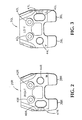
- the femoral positioning jig 20 is provided with a pair of posterior skids 36, 38, one for the lateral posterior condyle 9 and one for the medial posterior condyle 11, a pair of holes 40, 42 (preferably anterior bushings) for attaching the jig 20 to the resected distal femur 13 with spikes, and a pair of holes 44, 46 for receiving the two posterior drill bushings 32, 34.
- the lateral hole 46 is oblong or kidney shaped and angle indicia 47 are provided on the jig on the lateral side of the lateral hole as described in more detail below.
- two different femoral positioning jigs 20R, 20L are provided, one for the right knee and one for the left knee (where right and left are as viewed by the patient). Both jigs are substantially the same but for the relative locations of the holes 44 and 46.
- the circular hole 44R of the right jig 20R is on the right side of the jig 20R as viewed by the surgeon and the oblong hole 46R is on the left side of the jig 20R as viewed by the surgeon.
- the circular hole 44L of the left jig 20L is on the left side of the jig 20L as viewed by the surgeon and the oblong hole 46L is on the right side of the jig 20L as viewed by the surgeon.
- Angle indicia 47R, 47L are provided (preferably inscribed) on the portion of the jig 20R, 20L immediately lateral to the lateral oblong (or kidney shaped) hole 46R, 46L.
- the jigs 20R, 20L are individually attachable to (and removable from) the bushing bracket 16 by sliding the jig onto the bracket 16 such that the posterior drill bushings 32, 34 extend into the holes 44, 46.
- a method of using the apparatus 10 includes the following steps. After the proximal tibia 15 and distal femur 7 are resected in a conventional manner, the knee is moved to the flexion position and the femoral positioning jig (20A or 20B, referred to generally as 20) is placed against the distal end 13 of the femur 7 with the posterior skids 36, 38 located under the posterior condyles 9, 11.
- the jig When the jig is in position on the femur, it is secured in place with spikes (not shown) which are placed through the spike holes (anterior bushings) 40, 42 in the jig.
- the rack 14 and locking pinion 18 are adjusted, if necessary, to bring the drill bushing bracket 16 closest to the tibia engaging plate 12.
- the tibia engaging plate 12 is placed on the tibial plateau 17 and the drill bushings 32, 34 are inserted into the drill bushing holes 44, 46 on the femoral positioning jig 20.
- the locking pinion 18 is rotated so that the drill bushing bracket 16 is moved away from the tibia engaging plate 12 as shown in Figure 4. This results in the femoral positioning jig 20 and the femur 7 being moved away from the tibial plateau 17 and a tensioning of the collateral ligaments (not shown).
- the femur will not rotate and the positioning jig 20 will assume the position shown in Figure 5 for the right knee or Figure 7 for the left knee. If the medial ligament is shorter or tighter than the lateral ligament, the femur 7 and the positioning jig 20 will rotate in the internal (valgus) direction about the medial drill bushing (32 for the right leg, 34 for the left leg) when the ligaments are fully tensioned. The angle of rotation will be indicated on the scale 47 adjacent the oblong hole 46 in the femoral positioning jig 20 as shown in Figures 6 and 8.
- the surgeon may elect to remove some of the medial collateral ligaments to lessen the degree of rotation.
- the axes of the drill bushings 32, 34 still define a line which is parallel to the tibial plateau 17. Therefore, after removing ligaments (if necessary), the surgeon drills two holes in the distal femur 13, one being drilled through each drill bushing 32, 34. The locking pinion member 18 is then unlocked to remove tension from the ligaments and the apparatus 10 is removed from the knee.
- the distal end 13 of the femur 7 now has two holes in it and the axes of these holes define a line which is parallel to the tibial plateau 17 when the ligaments are taut. These holes are now used to attach a cutting block which will result in a precise resection of the posterior femoral condyles relative 9, 11 to the resected tibial plateau 17.
- the apparatus has been shown and described with two different removable positioning jigs, it is within the scope of the invention to provide separate apparatus for left and right legs where the left and right positioning jigs are not removable from the respective apparatus.
- the tibia engaging plate has been shown with two posterior skids, more or fewer skids can achieve substantially the same results.
- the apparatus has been shown and described as having a rack and pinion arrangement for moving the drill bushing bracket relative to the tibia engaging plate, it will be appreciated that other designs could achieve the same results in substantially the same way.
- femoral positioning jig has been shown as having a particular shape with particular locations for the spike holes, it will be understood that a positioning jig having a different shape can achieve the same results and that different means for securing the jig to the femur can also achieve the same results. It will therefore be appreciated by those skilled in the art that yet other modifications could be made to the provided invention without deviating from its scope as claimed.
Landscapes
- Health & Medical Sciences (AREA)
- Surgery (AREA)
- Life Sciences & Earth Sciences (AREA)
- Medical Informatics (AREA)
- Animal Behavior & Ethology (AREA)
- Orthopedic Medicine & Surgery (AREA)
- Oral & Maxillofacial Surgery (AREA)
- Engineering & Computer Science (AREA)
- Biomedical Technology (AREA)
- Heart & Thoracic Surgery (AREA)
- Dentistry (AREA)
- Molecular Biology (AREA)
- Nuclear Medicine, Radiotherapy & Molecular Imaging (AREA)
- General Health & Medical Sciences (AREA)
- Public Health (AREA)
- Veterinary Medicine (AREA)
- Physical Education & Sports Medicine (AREA)
- Transplantation (AREA)
- Prostheses (AREA)
- Surgical Instruments (AREA)
Claims (16)
- Chirurgische Vorrichtung 10 zum Spannen von Weichgeweben zwischen dem Femur und der Tibia während einer Kniearthroplastie, umfassend:(a) eine erste Eingriffseinrichtung 12 zum Eingriff mit einem tibialen Plateau;(b) eine zweite Eingriffseinrichtung 20,36,38 zum Eingriff mit einem medialen und lateralen femoralen Kondylus;(c) eine Translationseinrichtung 14,16,18, die mit der ersten und zweiten Eingriffseinrichtung verbunden ist, um die Eingriffseinrichtungen in Bezug zueinander translatorisch zu bewegen; und(d) eine mediale Drehverbindungseinrichtung 32,34, um die zweite Eingriffseinrichtung so mit der Translationseinrichtung zu verbinden, dass sich die zweite Eingriffseinrichtung frei um einen Punkt drehen kann, der im Wesentlichen mit dem medialen femoralen Kondylus ausgerichtet ist.
- Chirurgische Vorrichtung nach Anspruch 1, weiter umfassend eine Winkelanzeigeeinrichtung 33,35, um einen Drehwinkel der zweiten Eingriffseinrichtung anzuzeigen.
- Chirurgische Vorrichtung nach Anspruch 1, weiter umfassend eine Positioniereinrichtung 32,34, die mit der Translationseinrichtung verbunden ist, um mindestens zwei Punkte auf dem Femur so zu positionieren, dass die beiden Punkte eine Linie definieren, die im Wesentlichen parallel zum tibialen Plateau ist.
- Chirurgische Vorrichtung nach Anspruch 3, bei der die Positioniereinrichtung ein Paar im Abstand angeordnete Bohrbuchsen 32,34 einschließt.
- Chirurgische Vorrichtung nach Anspruch 1, bei der die zweite Eingriffseinrichtung eine Einrichtung 40,42 zum Befestigen der zweiten Eingriffseinrichtung am Femur einschließt.
- Chirurgische Vorrichtung nach Anspruch 5, bei der die Einrichtung zum Befestigen ein Paar im Abstand angeordnete Nagelöffnungen 40,42 einschließt.
- Chirurgische Vorrichtung nach Anspruch 1, weiter umfassend. eine Anterior-Posterior-Positioniereinrichtung 28,30, um die erste Eingriffseinrichtung in Bezug zur zweiten Eingriffseinrichtung anterior-posterior zu positionieren.
- Chirurgische Vorrichtung zum Spannen von Weichgeweben zwischen dem Femur und der Tibia während einer Kniearthroplastie, umfassend:(a) eine tibiale Eingriffseinrichtung 12, um mit einem resezierten tibialen Plateau in Eingriff zu treten;(b) einen Bohrbuchsenausleger 16 mit einer lateralen Bohrbuchse 32,34 und einer medialen Bohrbuchse 32,34, wobei jede Bohrbuchse eine Achse aufweist, wobei die Achsen des Paars von Bohrbuchsen eine erste Ebene definieren;(c) eine Translationseinrichtung 14,18, die mit der tibialen Eingriffseinrichtung 12 und dem Bohrbuchsenausleger 16 verbunden ist, um den Bohrbuchsenausleger in Bezug zur tibialen Eingriffseinrichtung translatorisch zu bewegen; und(d) eine femorale Positionierlehre 20, die drehbar mit der medialen Bohrbuchse verbunden ist, wobei die femorale Positionierlehre eine mit dem posterioren medialen Kondylus in Eingriff tretenden Kufe 38, eine mit dem posterioren lateralen Kondylus in Eingriff tretende Kufe 36 und eine Einrichtung zum Sichern der Position der Lehre in Bezug zum Femur 40,42 aufweist, wobei die erste Ebene im Wesentlichen parallel zum resezierten tibialen Plateau bleibt, wenn die tibiale Eingriffseinrichtung mit dem Plateau im Eingriff steht, und sich die Positionierlehre und der Femur frei um die mediale Bohrbuchse drehen können, wenn die Positionierlehre am Femur befestigt ist.
- Chirurgische Vorrichtung nach Anspruch 8, weiter umfassend Winkelmarkierungen 33,35, um einen Drehwinkel des Femur um die mediale Bohrbuchse anzuzeigen.
- Chirurgische Vorrichtung nach Anspruch 8, bei der die Positionierlehre eine im Wesentlichen kreisförmige mediale Öffnung 44 zur Aufnahme der medialen Bohrbuchse und eine im Wesentlichen längliche laterale Öffnung 46 zur Aufnahme der lateralen Bohrbuchse aufweist, so dass die drehbare Verbindung der Positionierlehre durch Einführen der medialen Bohrbuchse in die mediale Öffnung und der lateralen Bohrbuchse in die laterale Öffnung bewirkt wird.
- Chirurgische Vorrichtung nach Anspruch 10, bei der die Positionierlehre lösbar mit der medialen Bohrbuchse verbunden ist.
- Chirurgische Vorrichtung nach Anspruch 11, weiter umfassend eine getrennte linke und rechte Positionierlehre, wobei die linke Positionierlehre zur Verwendung mit einem linken Bein und die rechte Positionierlehre zur Verwendung mit einem rechten Bein vorgesehen ist.
- Chirurgische Vorrichtung nach Anspruch 9, bei der die Winkelmarkierungen Markierungen 33,35 auf einem lateralen Teil des Bohrbuchsenauslegers 16 und Markierungen auf einem lateralen Teil der Positionierlehre 20 einschließen.
- Chirurgische Vorrichtung nach Anspruch 9, bei der die Translationseinrichtung eine Zahnstange 14 und ein Ritzel 18 einschließt.
- Chirurgische Vorrichtung nach Anspruch 8, bei der die Tibiaeingriffseinrichtung eine laterale posteriore Kufe 22 und eine mediale posteriore Kufe 24 einschließt.
- Chirurgische Vorrichtung nach Anspruch 8, bei der die Einrichtung zum Sichern der Position der Lehre in Bezug zum Femur ein Paar Nagelöffnungen 40,42 in der Positionierlehre einschließt.
Applications Claiming Priority (2)
| Application Number | Priority Date | Filing Date | Title |
|---|---|---|---|
| US08/929,034 US5860980A (en) | 1997-09-15 | 1997-09-15 | Surgical apparatus for use in total knee arthroplasty and surgical methods for using said apparatus |
| US929034 | 1997-09-15 |
Publications (3)
| Publication Number | Publication Date |
|---|---|
| EP0903111A2 EP0903111A2 (de) | 1999-03-24 |
| EP0903111A3 EP0903111A3 (de) | 2002-10-30 |
| EP0903111B1 true EP0903111B1 (de) | 2004-03-03 |
Family
ID=25457217
Family Applications (1)
| Application Number | Title | Priority Date | Filing Date |
|---|---|---|---|
| EP98306816A Expired - Lifetime EP0903111B1 (de) | 1997-09-15 | 1998-08-26 | Chirurgischer Apparat für totale Kniegelenkrekonstruktion |
Country Status (4)
| Country | Link |
|---|---|
| US (1) | US5860980A (de) |
| EP (1) | EP0903111B1 (de) |
| JP (1) | JPH11164845A (de) |
| DE (1) | DE69822055T2 (de) |
Cited By (1)
| Publication number | Priority date | Publication date | Assignee | Title |
|---|---|---|---|---|
| US9192459B2 (en) | 2000-01-14 | 2015-11-24 | Bonutti Skeletal Innovations Llc | Method of performing total knee arthroplasty |
Families Citing this family (199)
| Publication number | Priority date | Publication date | Assignee | Title |
|---|---|---|---|---|
| US6056756A (en) * | 1998-08-11 | 2000-05-02 | Johnson & Johnson Professional, Inc. | Femoral tensing and sizing device |
| US6174314B1 (en) | 1998-12-15 | 2001-01-16 | David D. Waddell | In situ pattellar resection guide |
| CA2620783C (en) * | 1999-04-09 | 2011-04-05 | Evalve, Inc. | Methods and apparatus for cardiac valve repair |
| US6702821B2 (en) | 2000-01-14 | 2004-03-09 | The Bonutti 2003 Trust A | Instrumentation for minimally invasive joint replacement and methods for using same |
| US7104996B2 (en) * | 2000-01-14 | 2006-09-12 | Marctec. Llc | Method of performing surgery |
| US6379364B1 (en) | 2000-04-28 | 2002-04-30 | Synthes (Usa) | Dual drill guide for a locking bone plate |
| US6342057B1 (en) | 2000-04-28 | 2002-01-29 | Synthes (Usa) | Remotely aligned surgical drill guide |
| US6458135B1 (en) * | 2001-02-02 | 2002-10-01 | Howmedica Osteonics Corp. | Femoral guide for implanting a femoral knee prosthesis and method |
| US6629978B2 (en) * | 2001-04-23 | 2003-10-07 | Howmedica Osteonics Corp. | Valgus adapter |
| US7708741B1 (en) | 2001-08-28 | 2010-05-04 | Marctec, Llc | Method of preparing bones for knee replacement surgery |
| US8801720B2 (en) * | 2002-05-15 | 2014-08-12 | Otismed Corporation | Total joint arthroplasty system |
| US8388684B2 (en) * | 2002-05-23 | 2013-03-05 | Pioneer Signal Technology, Inc. | Artificial disc device |
| US7001433B2 (en) * | 2002-05-23 | 2006-02-21 | Pioneer Laboratories, Inc. | Artificial intervertebral disc device |
| AU2003287190A1 (en) * | 2002-10-23 | 2004-05-13 | Alastair J. T. Clemow | Modular femoral component for a total knee joint replacement for minimally invasive implantation |
| US7094241B2 (en) * | 2002-11-27 | 2006-08-22 | Zimmer Technology, Inc. | Method and apparatus for achieving correct limb alignment in unicondylar knee arthroplasty |
| US7029477B2 (en) * | 2002-12-20 | 2006-04-18 | Zimmer Technology, Inc. | Surgical instrument and positioning method |
| US7789885B2 (en) * | 2003-01-15 | 2010-09-07 | Biomet Manufacturing Corp. | Instrumentation for knee resection |
| US8551100B2 (en) | 2003-01-15 | 2013-10-08 | Biomet Manufacturing, Llc | Instrumentation for knee resection |
| US7837690B2 (en) * | 2003-01-15 | 2010-11-23 | Biomet Manufacturing Corp. | Method and apparatus for less invasive knee resection |
| US7887542B2 (en) * | 2003-01-15 | 2011-02-15 | Biomet Manufacturing Corp. | Method and apparatus for less invasive knee resection |
| US6916324B2 (en) * | 2003-02-04 | 2005-07-12 | Zimmer Technology, Inc. | Provisional orthopedic prosthesis for partially resected bone |
| US7235080B2 (en) * | 2003-02-20 | 2007-06-26 | Zimmer Technology, Inc. | Femoral reference tibial cut guide |
| ATE327715T1 (de) * | 2003-04-25 | 2006-06-15 | Zimmer Gmbh | Vorrichtung zur vorbereitung einer femurkondyle |
| FR2857576B1 (fr) * | 2003-07-16 | 2005-10-14 | Depuy France | Dispositif d'aide pour l'implantation de protheses totales du genou |
| US7686810B2 (en) * | 2003-08-29 | 2010-03-30 | Hs West Investments, Llc | Suture separation and organization devices for use with graft tensioning device |
| ATE289787T1 (de) | 2003-09-15 | 2005-03-15 | Zimmer Gmbh | Einstellvorrichtung |
| US7585328B2 (en) * | 2003-11-06 | 2009-09-08 | Haas Steven B | Minimally invasive knee arthroplasty |
| US7488324B1 (en) * | 2003-12-08 | 2009-02-10 | Biomet Manufacturing Corporation | Femoral guide for implanting a femoral knee prosthesis |
| US7282054B2 (en) * | 2003-12-26 | 2007-10-16 | Zimmer Technology, Inc. | Adjustable cut block |
| US7641661B2 (en) | 2003-12-26 | 2010-01-05 | Zimmer Technology, Inc. | Adjustable resection guide |
| US8758355B2 (en) | 2004-02-06 | 2014-06-24 | Synvasive Technology, Inc. | Dynamic knee balancer with pressure sensing |
| US7442196B2 (en) * | 2004-02-06 | 2008-10-28 | Synvasive Technology, Inc. | Dynamic knee balancer |
| US8167888B2 (en) * | 2004-08-06 | 2012-05-01 | Zimmer Technology, Inc. | Tibial spacer blocks and femoral cutting guide |
| CN101083944B (zh) * | 2004-12-21 | 2013-01-02 | 史密夫和内修有限公司 | 具有可移动的切割引导装置的远端股骨试验装置 |
| US12575818B2 (en) | 2005-02-08 | 2026-03-17 | G. Lynn Rasmussen | Arthroplasty systems and methods for optimally aligning and tensioning a knee prosthesis |
| US8317797B2 (en) | 2005-02-08 | 2012-11-27 | Rasmussen G Lynn | Arthroplasty systems and methods for optimally aligning and tensioning a knee prosthesis |
| US8303597B2 (en) * | 2005-02-08 | 2012-11-06 | Rasmussen G Lynn | Systems and methods for guiding cuts to a femur and tibia during a knee arthroplasty |
| US7695479B1 (en) | 2005-04-12 | 2010-04-13 | Biomet Manufacturing Corp. | Femoral sizer |
| US20050267484A1 (en) * | 2005-08-18 | 2005-12-01 | Jeff Menzner | Extended trochanteric osteotomy guide |
| US7780671B2 (en) * | 2006-01-23 | 2010-08-24 | Zimmer Technology, Inc. | Bone resection apparatus and method for knee surgery |
| US9808262B2 (en) * | 2006-02-15 | 2017-11-07 | Howmedica Osteonics Corporation | Arthroplasty devices and related methods |
| CA2642615A1 (en) * | 2006-02-15 | 2007-08-30 | Otismed Corp | Arthroplasty jigs and related methods |
| US8603180B2 (en) | 2006-02-27 | 2013-12-10 | Biomet Manufacturing, Llc | Patient-specific acetabular alignment guides |
| US9918740B2 (en) | 2006-02-27 | 2018-03-20 | Biomet Manufacturing, Llc | Backup surgical instrument system and method |
| US7967868B2 (en) | 2007-04-17 | 2011-06-28 | Biomet Manufacturing Corp. | Patient-modified implant and associated method |
| US10278711B2 (en) * | 2006-02-27 | 2019-05-07 | Biomet Manufacturing, Llc | Patient-specific femoral guide |
| US8535387B2 (en) | 2006-02-27 | 2013-09-17 | Biomet Manufacturing, Llc | Patient-specific tools and implants |
| US9345548B2 (en) | 2006-02-27 | 2016-05-24 | Biomet Manufacturing, Llc | Patient-specific pre-operative planning |
| US8407067B2 (en) | 2007-04-17 | 2013-03-26 | Biomet Manufacturing Corp. | Method and apparatus for manufacturing an implant |
| US9289253B2 (en) | 2006-02-27 | 2016-03-22 | Biomet Manufacturing, Llc | Patient-specific shoulder guide |
| US9907659B2 (en) | 2007-04-17 | 2018-03-06 | Biomet Manufacturing, Llc | Method and apparatus for manufacturing an implant |
| US8858561B2 (en) * | 2006-06-09 | 2014-10-14 | Blomet Manufacturing, LLC | Patient-specific alignment guide |
| US9113971B2 (en) * | 2006-02-27 | 2015-08-25 | Biomet Manufacturing, Llc | Femoral acetabular impingement guide |
| US8864769B2 (en) * | 2006-02-27 | 2014-10-21 | Biomet Manufacturing, Llc | Alignment guides with patient-specific anchoring elements |
| US20110172672A1 (en) * | 2006-02-27 | 2011-07-14 | Biomet Manufacturing Corp. | Instrument with transparent portion for use with patient-specific alignment guide |
| US8608749B2 (en) | 2006-02-27 | 2013-12-17 | Biomet Manufacturing, Llc | Patient-specific acetabular guides and associated instruments |
| US20150335438A1 (en) | 2006-02-27 | 2015-11-26 | Biomet Manufacturing, Llc. | Patient-specific augments |
| US8092465B2 (en) | 2006-06-09 | 2012-01-10 | Biomet Manufacturing Corp. | Patient specific knee alignment guide and associated method |
| US8568487B2 (en) | 2006-02-27 | 2013-10-29 | Biomet Manufacturing, Llc | Patient-specific hip joint devices |
| US9173661B2 (en) | 2006-02-27 | 2015-11-03 | Biomet Manufacturing, Llc | Patient specific alignment guide with cutting surface and laser indicator |
| US7780672B2 (en) * | 2006-02-27 | 2010-08-24 | Biomet Manufacturing Corp. | Femoral adjustment device and associated method |
| US8241293B2 (en) | 2006-02-27 | 2012-08-14 | Biomet Manufacturing Corp. | Patient specific high tibia osteotomy |
| US8377066B2 (en) | 2006-02-27 | 2013-02-19 | Biomet Manufacturing Corp. | Patient-specific elbow guides and associated methods |
| US8070752B2 (en) * | 2006-02-27 | 2011-12-06 | Biomet Manufacturing Corp. | Patient specific alignment guide and inter-operative adjustment |
| US8591516B2 (en) | 2006-02-27 | 2013-11-26 | Biomet Manufacturing, Llc | Patient-specific orthopedic instruments |
| US9339278B2 (en) | 2006-02-27 | 2016-05-17 | Biomet Manufacturing, Llc | Patient-specific acetabular guides and associated instruments |
| US20110190899A1 (en) * | 2006-02-27 | 2011-08-04 | Biomet Manufacturing Corp. | Patient-specific augments |
| US8608748B2 (en) | 2006-02-27 | 2013-12-17 | Biomet Manufacturing, Llc | Patient specific guides |
| US8133234B2 (en) | 2006-02-27 | 2012-03-13 | Biomet Manufacturing Corp. | Patient specific acetabular guide and method |
| US8337508B2 (en) | 2006-03-20 | 2012-12-25 | Perception Raisonnement Action En Medecine | Distractor system |
| US8231631B2 (en) * | 2006-03-20 | 2012-07-31 | Perception Raisonnement Action En Medecine | Distractor system |
| GB0610572D0 (en) * | 2006-05-27 | 2006-07-05 | Depuy Int Ltd | Guide assembly |
| US8273131B2 (en) * | 2006-05-31 | 2012-09-25 | Biomet Manufacturing Corp. | Method and apparatus for positioning a multiple piece prosthesis |
| US9795399B2 (en) | 2006-06-09 | 2017-10-24 | Biomet Manufacturing, Llc | Patient-specific knee alignment guide and associated method |
| US7686812B2 (en) * | 2006-06-30 | 2010-03-30 | Howmedica Osteonics Corp. | Method for setting the rotational position of a femoral component |
| US8715350B2 (en) | 2006-09-15 | 2014-05-06 | Pioneer Surgical Technology, Inc. | Systems and methods for securing an implant in intervertebral space |
| EP2063817A4 (de) * | 2006-09-15 | 2012-04-18 | Pioneer Surgical Technology Inc | Gelenkarthroplastie-vorrichtung mit beweglichen elementen |
| PT2526876E (pt) * | 2006-10-11 | 2015-08-05 | Ignace Ghijselings | Dispositivo para a instalação da articulação do joelho da prótese do fémur |
| JP5379009B2 (ja) | 2006-10-31 | 2013-12-25 | スミス アンド ネフュー インコーポレーテッド | 試験的大腿骨プロテーゼ及びその使用 |
| US8460302B2 (en) * | 2006-12-18 | 2013-06-11 | Otismed Corporation | Arthroplasty devices and related methods |
| GB2447702A (en) | 2007-03-23 | 2008-09-24 | Univ Leeds | Surgical bone cutting template |
| US8265949B2 (en) | 2007-09-27 | 2012-09-11 | Depuy Products, Inc. | Customized patient surgical plan |
| US8398645B2 (en) | 2007-09-30 | 2013-03-19 | DePuy Synthes Products, LLC | Femoral tibial customized patient-specific orthopaedic surgical instrumentation |
| US8357111B2 (en) | 2007-09-30 | 2013-01-22 | Depuy Products, Inc. | Method and system for designing patient-specific orthopaedic surgical instruments |
| USD642263S1 (en) | 2007-10-25 | 2011-07-26 | Otismed Corporation | Arthroplasty jig blank |
| US8460303B2 (en) | 2007-10-25 | 2013-06-11 | Otismed Corporation | Arthroplasty systems and devices, and related methods |
| US10582934B2 (en) | 2007-11-27 | 2020-03-10 | Howmedica Osteonics Corporation | Generating MRI images usable for the creation of 3D bone models employed to make customized arthroplasty jigs |
| US8311306B2 (en) | 2008-04-30 | 2012-11-13 | Otismed Corporation | System and method for image segmentation in generating computer models of a joint to undergo arthroplasty |
| US8737700B2 (en) * | 2007-12-18 | 2014-05-27 | Otismed Corporation | Preoperatively planning an arthroplasty procedure and generating a corresponding patient specific arthroplasty resection guide |
| US8221430B2 (en) * | 2007-12-18 | 2012-07-17 | Otismed Corporation | System and method for manufacturing arthroplasty jigs |
| US8777875B2 (en) * | 2008-07-23 | 2014-07-15 | Otismed Corporation | System and method for manufacturing arthroplasty jigs having improved mating accuracy |
| US8545509B2 (en) | 2007-12-18 | 2013-10-01 | Otismed Corporation | Arthroplasty system and related methods |
| US8617171B2 (en) | 2007-12-18 | 2013-12-31 | Otismed Corporation | Preoperatively planning an arthroplasty procedure and generating a corresponding patient specific arthroplasty resection guide |
| US8480679B2 (en) | 2008-04-29 | 2013-07-09 | Otismed Corporation | Generation of a computerized bone model representative of a pre-degenerated state and useable in the design and manufacture of arthroplasty devices |
| US8160345B2 (en) | 2008-04-30 | 2012-04-17 | Otismed Corporation | System and method for image segmentation in generating computer models of a joint to undergo arthroplasty |
| US8715291B2 (en) * | 2007-12-18 | 2014-05-06 | Otismed Corporation | Arthroplasty system and related methods |
| US8734455B2 (en) * | 2008-02-29 | 2014-05-27 | Otismed Corporation | Hip resurfacing surgical guide tool |
| US8197489B2 (en) | 2008-06-27 | 2012-06-12 | Depuy Products, Inc. | Knee ligament balancer |
| US8617175B2 (en) * | 2008-12-16 | 2013-12-31 | Otismed Corporation | Unicompartmental customized arthroplasty cutting jigs and methods of making the same |
| US8337498B2 (en) | 2008-08-13 | 2012-12-25 | Rasmussen G Lynn | Systems and methods for providing a bone milling device |
| NZ591206A (en) | 2008-08-20 | 2013-06-28 | Synvasive Technology Inc | Sensing force during partial and total knee replacement surgery |
| US9439656B2 (en) | 2008-10-30 | 2016-09-13 | Synvasive Technology, Inc. | System for positioning a cutting guide in knee surgery |
| US20100198275A1 (en) | 2008-10-30 | 2010-08-05 | Synvavise Technology, Inc. | Force sensing distal femoral alignment system and method of use |
| US8551023B2 (en) * | 2009-03-31 | 2013-10-08 | Depuy (Ireland) | Device and method for determining force of a knee joint |
| US8597210B2 (en) | 2009-03-31 | 2013-12-03 | Depuy (Ireland) | System and method for displaying joint force data |
| US8556830B2 (en) | 2009-03-31 | 2013-10-15 | Depuy | Device and method for displaying joint force data |
| US8721568B2 (en) | 2009-03-31 | 2014-05-13 | Depuy (Ireland) | Method for performing an orthopaedic surgical procedure |
| US8740817B2 (en) | 2009-03-31 | 2014-06-03 | Depuy (Ireland) | Device and method for determining forces of a patient's joint |
| US8216244B2 (en) * | 2009-06-19 | 2012-07-10 | Wright Medical Technology, Inc. | Midline referencing femoral sizing caliper |
| FR2948274B1 (fr) * | 2009-07-24 | 2011-09-16 | Tornier Sa | Instrumentation chirurgicale pour la preparation a la pose d'une prothese de genou |
| DE102009028503B4 (de) | 2009-08-13 | 2013-11-14 | Biomet Manufacturing Corp. | Resektionsschablone zur Resektion von Knochen, Verfahren zur Herstellung einer solchen Resektionsschablone und Operationsset zur Durchführung von Kniegelenk-Operationen |
| WO2011049637A1 (en) * | 2009-10-23 | 2011-04-28 | Synvasive Technology, Inc. | Knee balancing for revision procedures |
| US8632547B2 (en) | 2010-02-26 | 2014-01-21 | Biomet Sports Medicine, Llc | Patient-specific osteotomy devices and methods |
| GB2479899A (en) | 2010-04-28 | 2011-11-02 | Biomet Uk Ltd | Alignment tool for use in joint replacement |
| GB2482702A (en) * | 2010-08-11 | 2012-02-15 | Biomet Uk Healthcare Ltd | Ligament balancer |
| US9271744B2 (en) | 2010-09-29 | 2016-03-01 | Biomet Manufacturing, Llc | Patient-specific guide for partial acetabular socket replacement |
| US9968376B2 (en) | 2010-11-29 | 2018-05-15 | Biomet Manufacturing, Llc | Patient-specific orthopedic instruments |
| US8672946B2 (en) * | 2011-02-11 | 2014-03-18 | Biomet Manfacturing, LLC | Method and apparatus for performing knee arthroplasty |
| US9241745B2 (en) | 2011-03-07 | 2016-01-26 | Biomet Manufacturing, Llc | Patient-specific femoral version guide |
| US8715289B2 (en) | 2011-04-15 | 2014-05-06 | Biomet Manufacturing, Llc | Patient-specific numerically controlled instrument |
| US8956364B2 (en) | 2011-04-29 | 2015-02-17 | Biomet Manufacturing, Llc | Patient-specific partial knee guides and other instruments |
| US8668700B2 (en) | 2011-04-29 | 2014-03-11 | Biomet Manufacturing, Llc | Patient-specific convertible guides |
| CH704354B1 (it) * | 2011-05-17 | 2012-07-13 | Medacta Int Sa | Attrezzature per allineare e bilanciare i legamenti del ginocchio. |
| US8532807B2 (en) | 2011-06-06 | 2013-09-10 | Biomet Manufacturing, Llc | Pre-operative planning and manufacturing method for orthopedic procedure |
| US9084618B2 (en) | 2011-06-13 | 2015-07-21 | Biomet Manufacturing, Llc | Drill guides for confirming alignment of patient-specific alignment guides |
| US8939986B2 (en) | 2011-06-30 | 2015-01-27 | Depuy (Ireland) | Surgical instruments for use in surgically preparing a tibia for implantation of a prosthetic component |
| US8986390B2 (en) | 2011-06-30 | 2015-03-24 | Depuy (Ireland) | Method of trialing a knee prosthesis |
| US20130006378A1 (en) | 2011-06-30 | 2013-01-03 | Wogoman Thomas E | Polymer femoral trial component |
| US8926619B2 (en) | 2011-06-30 | 2015-01-06 | Depuy (Ireland) | Method of surgically preparing a tibia for implantation of a prosthetic component |
| US8968412B2 (en) | 2011-06-30 | 2015-03-03 | Depuy (Ireland) | Trialing system for a knee prosthesis and method of use |
| US8951301B2 (en) | 2011-06-30 | 2015-02-10 | Depuy (Ireland) | Method of using a trialing system for a knee prosthesis |
| US8852197B2 (en) | 2011-06-30 | 2014-10-07 | Depuy (Ireland) | Surgical instrument assemblies for use in surgically preparing a tibia for implantation of a prosthetic component |
| US20130001121A1 (en) | 2011-07-01 | 2013-01-03 | Biomet Manufacturing Corp. | Backup kit for a patient-specific arthroplasty kit assembly |
| US8764760B2 (en) | 2011-07-01 | 2014-07-01 | Biomet Manufacturing, Llc | Patient-specific bone-cutting guidance instruments and methods |
| EP3326542B1 (de) * | 2011-07-19 | 2019-09-25 | Zimmer, Inc. | Instrument für kniearthroplastik |
| US8597365B2 (en) | 2011-08-04 | 2013-12-03 | Biomet Manufacturing, Llc | Patient-specific pelvic implants for acetabular reconstruction |
| US9295497B2 (en) | 2011-08-31 | 2016-03-29 | Biomet Manufacturing, Llc | Patient-specific sacroiliac and pedicle guides |
| US9066734B2 (en) | 2011-08-31 | 2015-06-30 | Biomet Manufacturing, Llc | Patient-specific sacroiliac guides and associated methods |
| GB201115411D0 (en) | 2011-09-07 | 2011-10-19 | Depuy Ireland | Surgical instrument |
| US9918723B2 (en) * | 2011-09-23 | 2018-03-20 | Depuy Mitek, Llc | Glenoid anchor guide |
| EP2775966B1 (de) | 2011-10-24 | 2015-09-16 | Synvasive Technology, Inc. | Kniebalancesysteme |
| KR20130046337A (ko) | 2011-10-27 | 2013-05-07 | 삼성전자주식회사 | 멀티뷰 디바이스 및 그 제어방법과, 디스플레이장치 및 그 제어방법과, 디스플레이 시스템 |
| US9554910B2 (en) | 2011-10-27 | 2017-01-31 | Biomet Manufacturing, Llc | Patient-specific glenoid guide and implants |
| US9301812B2 (en) | 2011-10-27 | 2016-04-05 | Biomet Manufacturing, Llc | Methods for patient-specific shoulder arthroplasty |
| WO2013062848A1 (en) | 2011-10-27 | 2013-05-02 | Biomet Manufacturing Corporation | Patient-specific glenoid guides |
| US9451973B2 (en) | 2011-10-27 | 2016-09-27 | Biomet Manufacturing, Llc | Patient specific glenoid guide |
| US9241807B2 (en) | 2011-12-23 | 2016-01-26 | Pioneer Surgical Technology, Inc. | Systems and methods for inserting a spinal device |
| US9237950B2 (en) | 2012-02-02 | 2016-01-19 | Biomet Manufacturing, Llc | Implant with patient-specific porous structure |
| US9381011B2 (en) | 2012-03-29 | 2016-07-05 | Depuy (Ireland) | Orthopedic surgical instrument for knee surgery |
| US10070973B2 (en) | 2012-03-31 | 2018-09-11 | Depuy Ireland Unlimited Company | Orthopaedic sensor module and system for determining joint forces of a patient's knee joint |
| US10206792B2 (en) | 2012-03-31 | 2019-02-19 | Depuy Ireland Unlimited Company | Orthopaedic surgical system for determining joint forces of a patients knee joint |
| US10098761B2 (en) | 2012-03-31 | 2018-10-16 | DePuy Synthes Products, Inc. | System and method for validating an orthopaedic surgical plan |
| US9545459B2 (en) | 2012-03-31 | 2017-01-17 | Depuy Ireland Unlimited Company | Container for surgical instruments and system including same |
| US9050197B2 (en) * | 2012-07-23 | 2015-06-09 | Biomet Manufacturing, Llc | Knee sizing and balancing instrument |
| GB2506616B (en) * | 2012-10-03 | 2018-12-05 | Corin Ltd | Leg alignment apparatus and method |
| US9402637B2 (en) | 2012-10-11 | 2016-08-02 | Howmedica Osteonics Corporation | Customized arthroplasty cutting guides and surgical methods using the same |
| US9060788B2 (en) | 2012-12-11 | 2015-06-23 | Biomet Manufacturing, Llc | Patient-specific acetabular guide for anterior approach |
| US9204977B2 (en) | 2012-12-11 | 2015-12-08 | Biomet Manufacturing, Llc | Patient-specific acetabular guide for anterior approach |
| GB201302782D0 (en) * | 2013-02-18 | 2013-04-03 | Depuy Ireland | A guide for locating a cutting block on a patient's femur |
| USD696782S1 (en) | 2013-03-08 | 2013-12-31 | Stryker Corporation | Joint stabilizing instrument |
| US9839438B2 (en) | 2013-03-11 | 2017-12-12 | Biomet Manufacturing, Llc | Patient-specific glenoid guide with a reusable guide holder |
| US9579107B2 (en) | 2013-03-12 | 2017-02-28 | Biomet Manufacturing, Llc | Multi-point fit for patient specific guide |
| US9498233B2 (en) | 2013-03-13 | 2016-11-22 | Biomet Manufacturing, Llc. | Universal acetabular guide and associated hardware |
| US9826981B2 (en) | 2013-03-13 | 2017-11-28 | Biomet Manufacturing, Llc | Tangential fit of patient-specific guides |
| US9517145B2 (en) | 2013-03-15 | 2016-12-13 | Biomet Manufacturing, Llc | Guide alignment system and method |
| GB2516674A (en) * | 2013-07-29 | 2015-02-04 | Ramesh Chandra | Orthopaedic Apparatus |
| US20150112349A1 (en) | 2013-10-21 | 2015-04-23 | Biomet Manufacturing, Llc | Ligament Guide Registration |
| JP6336811B2 (ja) * | 2014-04-16 | 2018-06-06 | ジンマー・バイオメット合同会社 | 人工膝関節設置用ジグ |
| US10282488B2 (en) | 2014-04-25 | 2019-05-07 | Biomet Manufacturing, Llc | HTO guide with optional guided ACL/PCL tunnels |
| US9861491B2 (en) | 2014-04-30 | 2018-01-09 | Depuy Ireland Unlimited Company | Tibial trial system for a knee prosthesis |
| US9408616B2 (en) | 2014-05-12 | 2016-08-09 | Biomet Manufacturing, Llc | Humeral cut guide |
| US9561040B2 (en) | 2014-06-03 | 2017-02-07 | Biomet Manufacturing, Llc | Patient-specific glenoid depth control |
| US9839436B2 (en) | 2014-06-03 | 2017-12-12 | Biomet Manufacturing, Llc | Patient-specific glenoid depth control |
| US9826994B2 (en) | 2014-09-29 | 2017-11-28 | Biomet Manufacturing, Llc | Adjustable glenoid pin insertion guide |
| US9833245B2 (en) | 2014-09-29 | 2017-12-05 | Biomet Sports Medicine, Llc | Tibial tubercule osteotomy |
| CN107106189B (zh) | 2014-11-19 | 2019-12-13 | 捷迈有限公司 | 间隙校准股骨测量器 |
| US9820868B2 (en) | 2015-03-30 | 2017-11-21 | Biomet Manufacturing, Llc | Method and apparatus for a pin apparatus |
| US10226262B2 (en) | 2015-06-25 | 2019-03-12 | Biomet Manufacturing, Llc | Patient-specific humeral guide designs |
| US10568647B2 (en) | 2015-06-25 | 2020-02-25 | Biomet Manufacturing, Llc | Patient-specific humeral guide designs |
| US10195056B2 (en) | 2015-10-19 | 2019-02-05 | Depuy Ireland Unlimited Company | Method for preparing a patient's tibia to receive an implant |
| US10537445B2 (en) | 2015-10-19 | 2020-01-21 | Depuy Ireland Unlimited Company | Surgical instruments for preparing a patient's tibia to receive an implant |
| AU2017268038B2 (en) * | 2016-05-19 | 2020-01-30 | Knee Balancer IP Pty Ltd | An arrangement and method in the preparation of the distal femur and posterior femoral condyle proximal surfaces of the femur for the femoral component of a prosthetic knee joint |
| EP3474725A1 (de) | 2016-06-24 | 2019-05-01 | Surgical Sensors BVBA | Integrierte bänderbelastungsmessung |
| US12414862B2 (en) | 2016-11-30 | 2025-09-16 | G. Lynn Rasmussen | Systems and methods for providing a tibial baseplate system |
| WO2018102610A2 (en) | 2016-11-30 | 2018-06-07 | Rasmussen G Lynn | Systems and methods for providing a tibial baseplate |
| US11266512B2 (en) | 2016-12-22 | 2022-03-08 | Orthosensor Inc. | Surgical apparatus to support installation of a prosthetic component and method therefore |
| US11291437B2 (en) | 2016-12-22 | 2022-04-05 | Orthosensor Inc. | Tilting surgical tensor to support at least one bone cut |
| US11284873B2 (en) | 2016-12-22 | 2022-03-29 | Orthosensor Inc. | Surgical tensor where each distraction mechanism is supported and aligned by at least two guide shafts |
| US11185425B2 (en) | 2016-12-22 | 2021-11-30 | Orthosensor Inc. | Surgical tensor configured to distribute loading through at least two pivot points |
| US10772640B2 (en) | 2016-12-22 | 2020-09-15 | Orthosensor Inc. | Surgical apparatus having a medial plate and a lateral plate and method therefore |
| US11540928B2 (en) * | 2017-03-03 | 2023-01-03 | Engage Uni Llc | Unicompartmental knee arthroplasty |
| US10722310B2 (en) | 2017-03-13 | 2020-07-28 | Zimmer Biomet CMF and Thoracic, LLC | Virtual surgery planning system and method |
| AU2017425028B2 (en) | 2017-07-28 | 2020-11-26 | Wright Medical Technology, Inc. | Joint osteotomy system and method |
| JP7521152B2 (ja) | 2017-09-08 | 2024-07-24 | エクスタント メディカル ホールディングス,インコーポレイテッド. | 椎間インプラント、器具、及び方法 |
| USD907771S1 (en) | 2017-10-09 | 2021-01-12 | Pioneer Surgical Technology, Inc. | Intervertebral implant |
| US11051829B2 (en) | 2018-06-26 | 2021-07-06 | DePuy Synthes Products, Inc. | Customized patient-specific orthopaedic surgical instrument |
| EP4033968B1 (de) * | 2019-09-24 | 2025-12-17 | MAKO Surgical Corp. | System zum ausbalancieren von ligamenten unter verwendung einer robotisch gehaltenen vorrichtung |
| US20210228377A1 (en) | 2020-01-29 | 2021-07-29 | Howmedica Osteonics Corp. | Load Sensor Balancer Instruments |
| US20230066435A1 (en) * | 2021-08-31 | 2023-03-02 | Corin Limited | Orthopedic surgery system for soft tissue balancing and implant planning |
Family Cites Families (6)
| Publication number | Priority date | Publication date | Assignee | Title |
|---|---|---|---|---|
| US4566448A (en) * | 1983-03-07 | 1986-01-28 | Rohr Jr William L | Ligament tensor and distal femoral resector guide |
| US5116338A (en) * | 1988-02-03 | 1992-05-26 | Pfizer Hospital Products Group, Inc. | Apparatus for knee prosthesis |
| GB9123555D0 (en) * | 1991-11-06 | 1992-01-02 | Attfield Stephen F | Tensile balancer |
| US5213112A (en) * | 1992-01-29 | 1993-05-25 | Pfizer Hospital Products Group, Inc. | Tension meter for orthopedic surgery |
| US5597379A (en) * | 1994-09-02 | 1997-01-28 | Hudson Surgical Design, Inc. | Method and apparatus for femoral resection alignment |
| US5540696A (en) * | 1995-01-06 | 1996-07-30 | Zimmer, Inc. | Instrumentation for use in orthopaedic surgery |
-
1997
- 1997-09-15 US US08/929,034 patent/US5860980A/en not_active Expired - Lifetime
-
1998
- 1998-08-26 DE DE69822055T patent/DE69822055T2/de not_active Expired - Fee Related
- 1998-08-26 EP EP98306816A patent/EP0903111B1/de not_active Expired - Lifetime
- 1998-09-14 JP JP10259672A patent/JPH11164845A/ja active Pending
Cited By (1)
| Publication number | Priority date | Publication date | Assignee | Title |
|---|---|---|---|---|
| US9192459B2 (en) | 2000-01-14 | 2015-11-24 | Bonutti Skeletal Innovations Llc | Method of performing total knee arthroplasty |
Also Published As
| Publication number | Publication date |
|---|---|
| DE69822055T2 (de) | 2004-07-22 |
| US5860980A (en) | 1999-01-19 |
| EP0903111A2 (de) | 1999-03-24 |
| EP0903111A3 (de) | 2002-10-30 |
| DE69822055D1 (de) | 2004-04-08 |
| JPH11164845A (ja) | 1999-06-22 |
Similar Documents
| Publication | Publication Date | Title |
|---|---|---|
| EP0903111B1 (de) | Chirurgischer Apparat für totale Kniegelenkrekonstruktion | |
| US9855057B2 (en) | Natural alignment knee instruments | |
| US6059788A (en) | Method and apparatus for locating bone cuts at the distal condylar femur region to receive a femoral prosthesis and properly articulated with patellar and tibial prosthesis | |
| US5720752A (en) | Distal femoral cutting guide apparatus with anterior or posterior referencing for use in knee joint replacement surgery | |
| EP0975262B1 (de) | Instrument zur auswertung des gleichgewichts eines kniegelenks | |
| US6077270A (en) | Method and apparatus for locating bone cuts at the distal condylar femur region to receive a femoral prothesis and to coordinate tibial and patellar resection and replacement with femoral resection and replacement | |
| EP1226788B1 (de) | Rechnerunterstütztes System für Kniegelenkrekonstruktion | |
| US6575980B1 (en) | Method and apparatus for femoral resection | |
| EP1424042B1 (de) | Vorrichtung zum Ausrichten des Beines für eine unikondylare Arthroplastie des Knies | |
| US6758850B2 (en) | Instruments and methods for flexion gap adjustment | |
| US5569261A (en) | Distal femoral cutting guide apparatus with anterior or posterior referencing for use in knee joint replacement surgery | |
| US7329260B2 (en) | Kit, guide and method for locating distal femoral resection plane | |
| US4646729A (en) | Prosthetic knee implantation | |
| US20110046685A1 (en) | Surgical instrument for fitting a knee prosthesis | |
| US20040153066A1 (en) | Apparatus for knee surgery and method of use | |
| US12161346B2 (en) | Knee resection and gap balancing instruments and techniques for kinematic alignment | |
| JP2001525536A (ja) | 大腿骨、脛骨および膝蓋骨の遠位顆に切除を位置づけるための方法および装置 | |
| AU2013326287B2 (en) | Leg alignment apparatus and method | |
| GB2495775A (en) | Femoral sizing jig, femur resecting system and method | |
| US9005208B2 (en) | Ligament balancing femoral trial | |
| AU2005202181A1 (en) | Navigated lateral/medial femoral resection guide | |
| WO2019207536A1 (en) | Cutting and drilling template for unicondylar knee arthroplasty | |
| WO2016153927A1 (en) | Disposable multi-purpose tool for total knee arthroplasty | |
| WO2018104704A1 (en) | Apparatus for alignment of knee arthroplasty tibial cutting block | |
| Cooke et al. | Universal bone cutting device for precision knee replacement arthroplasty and osteotomy |
Legal Events
| Date | Code | Title | Description |
|---|---|---|---|
| PUAI | Public reference made under article 153(3) epc to a published international application that has entered the european phase |
Free format text: ORIGINAL CODE: 0009012 |
|
| AK | Designated contracting states |
Kind code of ref document: A2 Designated state(s): AT BE CH CY DE DK ES FI FR GB GR IE IT LI LU MC NL PT SE |
|
| AX | Request for extension of the european patent |
Free format text: AL;LT;LV;MK;RO;SI |
|
| RAP1 | Party data changed (applicant data changed or rights of an application transferred) |
Owner name: STRYKER TECHNOLOGIES CORPORATION |
|
| PUAL | Search report despatched |
Free format text: ORIGINAL CODE: 0009013 |
|
| AK | Designated contracting states |
Kind code of ref document: A3 Designated state(s): AT BE CH CY DE DK ES FI FR GB GR IE IT LI LU MC NL PT SE |
|
| AX | Request for extension of the european patent |
Free format text: AL;LT;LV;MK;RO;SI |
|
| RIC1 | Information provided on ipc code assigned before grant |
Free format text: 7A 61B 17/15 A, 7A 61B 17/02 B, 7A 61F 2/46 B |
|
| 17P | Request for examination filed |
Effective date: 20030107 |
|
| AKX | Designation fees paid |
Designated state(s): DE FR GB IE IT |
|
| GRAP | Despatch of communication of intention to grant a patent |
Free format text: ORIGINAL CODE: EPIDOSNIGR1 |
|
| RTI1 | Title (correction) |
Free format text: SURGICAL APPARATUS FOR USE IN TOTAL KNEE ANTHROPLASTY |
|
| RTI1 | Title (correction) |
Free format text: SURGICAL APPARATUS FOR USE IN TOTAL KNEE ARTHROPLASTY |
|
| GRAS | Grant fee paid |
Free format text: ORIGINAL CODE: EPIDOSNIGR3 |
|
| GRAA | (expected) grant |
Free format text: ORIGINAL CODE: 0009210 |
|
| AK | Designated contracting states |
Kind code of ref document: B1 Designated state(s): DE FR GB IE IT |
|
| REG | Reference to a national code |
Ref country code: GB Ref legal event code: FG4D |
|
| REG | Reference to a national code |
Ref country code: IE Ref legal event code: FG4D |
|
| REF | Corresponds to: |
Ref document number: 69822055 Country of ref document: DE Date of ref document: 20040408 Kind code of ref document: P |
|
| RAP2 | Party data changed (patent owner data changed or rights of a patent transferred) |
Owner name: HOWMEDIA OSTEONICS CORP. |
|
| RAP2 | Party data changed (patent owner data changed or rights of a patent transferred) |
Owner name: HOWMEDICA OSTEONICS CORP. |
|
| ET | Fr: translation filed | ||
| RAP2 | Party data changed (patent owner data changed or rights of a patent transferred) |
Owner name: HOWMEDICA OSTEONICS CORP. |
|
| PLBE | No opposition filed within time limit |
Free format text: ORIGINAL CODE: 0009261 |
|
| STAA | Information on the status of an ep patent application or granted ep patent |
Free format text: STATUS: NO OPPOSITION FILED WITHIN TIME LIMIT |
|
| 26N | No opposition filed |
Effective date: 20041206 |
|
| PGFP | Annual fee paid to national office [announced via postgrant information from national office to epo] |
Ref country code: IE Payment date: 20070713 Year of fee payment: 10 |
|
| PGFP | Annual fee paid to national office [announced via postgrant information from national office to epo] |
Ref country code: DE Payment date: 20070831 Year of fee payment: 10 |
|
| PGFP | Annual fee paid to national office [announced via postgrant information from national office to epo] |
Ref country code: IT Payment date: 20070627 Year of fee payment: 10 Ref country code: GB Payment date: 20070705 Year of fee payment: 10 |
|
| PGFP | Annual fee paid to national office [announced via postgrant information from national office to epo] |
Ref country code: FR Payment date: 20070803 Year of fee payment: 10 |
|
| GBPC | Gb: european patent ceased through non-payment of renewal fee |
Effective date: 20080826 |
|
| REG | Reference to a national code |
Ref country code: IE Ref legal event code: MM4A |
|
| REG | Reference to a national code |
Ref country code: FR Ref legal event code: ST Effective date: 20090430 |
|
| PG25 | Lapsed in a contracting state [announced via postgrant information from national office to epo] |
Ref country code: IE Free format text: LAPSE BECAUSE OF NON-PAYMENT OF DUE FEES Effective date: 20080826 |
|
| PG25 | Lapsed in a contracting state [announced via postgrant information from national office to epo] |
Ref country code: IT Free format text: LAPSE BECAUSE OF NON-PAYMENT OF DUE FEES Effective date: 20080826 Ref country code: FR Free format text: LAPSE BECAUSE OF NON-PAYMENT OF DUE FEES Effective date: 20080901 Ref country code: DE Free format text: LAPSE BECAUSE OF NON-PAYMENT OF DUE FEES Effective date: 20090303 |
|
| PG25 | Lapsed in a contracting state [announced via postgrant information from national office to epo] |
Ref country code: GB Free format text: LAPSE BECAUSE OF NON-PAYMENT OF DUE FEES Effective date: 20080826 |