EP0903227B1 - Tour d'impression d'une machine à imprimer - Google Patents
Tour d'impression d'une machine à imprimer Download PDFInfo
- Publication number
- EP0903227B1 EP0903227B1 EP98113926A EP98113926A EP0903227B1 EP 0903227 B1 EP0903227 B1 EP 0903227B1 EP 98113926 A EP98113926 A EP 98113926A EP 98113926 A EP98113926 A EP 98113926A EP 0903227 B1 EP0903227 B1 EP 0903227B1
- Authority
- EP
- European Patent Office
- Prior art keywords
- printing
- roller
- cylinder
- inking mechanism
- forme
- Prior art date
- Legal status (The legal status is an assumption and is not a legal conclusion. Google has not performed a legal analysis and makes no representation as to the accuracy of the status listed.)
- Expired - Lifetime
Links
- 238000007639 printing Methods 0.000 title claims description 77
- 238000007645 offset printing Methods 0.000 claims description 35
- 238000007774 anilox coating Methods 0.000 description 15
- 238000004040 coloring Methods 0.000 description 7
- 238000011144 upstream manufacturing Methods 0.000 description 3
- 239000000654 additive Substances 0.000 description 2
- 238000006243 chemical reaction Methods 0.000 description 2
- 230000009849 deactivation Effects 0.000 description 2
- 230000000712 assembly Effects 0.000 description 1
- 238000000429 assembly Methods 0.000 description 1
- 239000003795 chemical substances by application Substances 0.000 description 1
- 238000007647 flexography Methods 0.000 description 1
- 230000003993 interaction Effects 0.000 description 1
- 239000004922 lacquer Substances 0.000 description 1
- 238000004519 manufacturing process Methods 0.000 description 1
- 238000010186 staining Methods 0.000 description 1
Images

Classifications
-
- B—PERFORMING OPERATIONS; TRANSPORTING
- B41—PRINTING; LINING MACHINES; TYPEWRITERS; STAMPS
- B41F—PRINTING MACHINES OR PRESSES
- B41F31/00—Inking arrangements or devices
Definitions
- the invention relates to a printing tower of a printing press.
- Printing towers which contain a printing form cylinder, an offset cylinder interacting with a printing cylinder and an inking and dampening unit (Teschner, Offsetdrucktechnik, ausschriften-Verlag Fellbach 1989, section 10.3.3 Farbwerke).
- the inking units are known in many embodiments; however, all embodiments contain typical elements, such as an upper part of an inking unit with at least one ink supply line and a lower part of an inking unit with at least one applicator roller group, which contains two applicator rollers and a distribution cylinder connecting them.
- the dampening units are also designed in several variants, the usual dampening units comprising a dampening roller, an upstream transfer roller and a duct roller rotating in a trough. These dampening units can be connected to the inking unit via a bridge roller to form an inking unit / dampening unit.
- These printing towers described are earmarked, ie only designed for offset printing.
- Printing towers for flexographic printing presses with anilox coloring are also known from the cited literature reference, an anilox roller with a chamber doctor blade device being assigned to the printing form cylinder for the application of low-viscosity printing ink.
- This printing tower is also designed for a specific purpose and is particularly unsuitable for high-quality inking of the printing form.
- EP-A-0764524 is a (lower) short inking unit of a web-fed rotary printing press that acts from below known with an anilox roller and a chamber doctor blade system.
- a pressure tower which can be used alternatively by one with partial use of already existing funds Roller inking unit can be converted to a short inking unit is not disclosed.
- EP-A-0257365 discloses a convertible inking unit of a sheet-fed rotary printing press, which is equipped both with a conventional roller inking unit and with a short inking unit containing a squeeze roller ink supply device.
- the short inking unit is suitable and usable due to the ink supply system used (squeeze roller inking unit) and the structure and interaction of the systems (introduction of the connecting roller in the opposite direction) for quality-reduced pressure work.
- From DE 3906648 A1 an application unit for lacquer with an anilox roller rotating in a trough and a doctor blade is known.
- the object of the invention is a printing tower of high variability for several purposes with the like Structure and / or with partial use of existing ones and / or by exchanging existing ones Means against other appropriate means.
- the solutions according to the invention ensure that existing conventional printing towers /, that in connection with a dampening unit for the coloring of offset printing forms or without Dampening unit for inking dry offset printing forms, with partial use of existing ones Agents using some additives for other purposes - anilox staining of Converted offset printing forms or dry offset printing forms or flexographic printing forms (clichés) can be (conversion variant) or that the equipment of machines with conventional Offset printing towers or flexographic printing towers or dry offset printing towers or offset printing towers, Flexographic printing towers or dry offset printing towers with anilox coloring in the manufacturing plant with partial use of the same means is easily possible (equipment variant).
- the equipment variant there is again a first equipment variant in which the Pressure tower is equipped for all purposes mentioned and when used for a specific purpose certain means are deactivated and a second equipment variant, in which the pressure tower is specially equipped for one or more purposes.
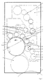
- the printing tower 1 shown in FIG. 1 for conventional offset printing contains a printing form cylinder 2 with an offset printing form 3, an offset cylinder 4 which is in operative connection with the printing form cylinder 2, usually covered with a rubber blanket, and an inking unit 6; 7 and a dampening unit 15.
- the offset cylinder 4 is operatively connected to a pressure cylinder 5 not arranged in the printing tower 1.
- the inking unit 6; 7 contains the two main assemblies, lower part of the inking unit 6 and upper part of the inking unit 7.
- the upper part of the inking unit 7 contains an ink supply line 8 with a divider roller 9 for connecting the upper part of the inking unit 7 to the lower part of the inking unit 6.
- the lower part of the inking unit 6 contains two applicator roller groups 10, each consisting of two applicator rollers 11 and a distribution cylinder 12 connecting them; an embodiment with only one applicator roller group is also possible.
- the connection between the lower and upper part of the inking unit is realized via the divider roller 9 and the distribution cylinder 12.
- the two applicator roller groups 10 are connected to one another either by a connecting roller 13 connecting their adjacent applicator rollers 11 and / or by a bridge group 14 connecting the distribution cylinders 12 to an even or an odd number of rollers.
- the dampening unit 15 consists of a dampening roller 16, an upstream transfer roller 17 and one of these upstream duct roller 18 which rotates in a trough 19.
- the dampening unit 15 can be connected to the applicator roller group 10 via a bridge roller 20 (active connection of the dampening applicator roller 16 / bridge roller 20 / applicator roller 11). If the printing form cylinder 2 is coated with a dry offset printing form 23, the dampening unit 15 is deactivated (indicated by a two-way arrow).
- a roller of the lower part of the inking unit 6 is an anilox roller 21 with a chamber doctor blade 22 assigned. In the inking unit configuration shown in FIG. 1, this roller is a roller of bridge group 14 with the same direction of rotation.
- the upper part of the inking unit 7 is either not present, ie the printing tower is equipped for special purposes or is deactivated, ie the printing tower is equipped for several purposes and certain means are deactivated when used for a specific purpose.
- the upper part of the inking unit 7 is present; the upper part of the inking unit 7 is missing for offset printing, dry offset and flexographic printing with anilox coloring, ie this is not installed.
- the printing form cylinder 2 is covered with an elastic flexographic printing plate 24.
- the upper part of the inking unit 7 is activated for conventional offset printing and dry offset printing and the upper part of the inking unit 7 is deactivated for offset printing, dry offset printing and flexographic printing with anilox inking. Deactivation takes place by removing the connection between the dividing roller 9 and the distribution cylinder 12.
- the ink transfer to the sheet to be printed takes place indirectly.
- the printing form cylinder is provided with a blanket covering instead of a printing form, i.e. this acts as an application cylinder and is the offset cylinder instead of a rubber blanket covered with a printing form (cliché), i.e. if this acts as a forme cylinder, the Ink transfer directly to the sheet to be printed.
Landscapes
- Inking, Control Or Cleaning Of Printing Machines (AREA)
Claims (10)
- Tour d'impression d'une machine d'impression, comprenant un cylindre offset (4) fonctionnant avec un cylindre d'impression (5) et un cylindre à matrice (2) fonctionnant en liaison avec la partie inférieure d'un mécanisme d'encrage (6), dans laquelle la partie inférieure du mécanisme d'encrage (6) comprend au moins un groupe de rouleaux toucheurs (10) ayant deux rouleaux toucheurs (11), et un rouleau de transfert (12) reliant les rouleaux toucheurs, et un dispositif d'amenée d'encre avec un rouleau de trame (21) tournant dans le même sens que le rouleau de la partie inférieure du mécanisme d'encrage (6), avec une raclette (22) associé à un rouleau de la partie inférieure du mécanisme d'encrage (6).
- Tour d'impression d'une machine d'impression, comprenant un cylindre à matrice constitué par le montage d'une matrice d'impression offset sur un cylindre offset (4) et fonctionnant avec un cylindre d'impression (5), et un cylindre toucheur formé par l'application d'une feuille de caoutchouc sur un cylindre à matrice (z) et fonctionnant avec une partie inférieure d'un mécanisme d'encrage, dans laquelle la partie inférieure du mécanisme d'encrage (6), comprend au moins un groupe de rouleaux toucheurs (10) ayant deux rouleaux toucheurs (11), et un rouleau de transfert (12) reliant les rouleaux toucheurs, et un rouleau de la partie inférieur du mécanisme d'encrage (6), et un dispositif d'amenée d'encre avec un rouleau de trame (21) tournant dans le même sens que le rouleau de la partie inférieure du mécanisme d'encrage (6), avec une raclette (22) associé à un rouleau de la partie inférieure du mécanisme d'encrage (6).
- Tour d'impression d'une machine d'impression suivant la revendication 1 ou 2,
caractérisée en ce que
la tour d'impression (1) comprend une partie supérieure d'un mécanisme d'encrage (7) associé à la partie inférieure du mécanisme d'encrage (6) et comprenant au moins une voie d'acheminement de l'encre (8), et la coopération de la partie inférieure avec la partie supérieure du mécanisme d'encrage (6 ; 7) est supprimée dès qu'ils sont séparés. - Tour d'impression suivant la revendication 1 ou 2,
caractérisée en ce que
la partie inférieure du mécanisme d'impression (6) se compose de deux groupes de rouleaux toucheurs (10) et d'un rouleau de liaison (13) reliant deux rouleaux toucheurs (11) faisant partie de groupes différents, et le rouleau de trame (21) avec raclette (22) est asservi à un rouleau toucheur (11). - Tour d'impression suivant la revendication 1 ou 2,
caractérisée en ce que
la partie inférieure du mécanisme d'impression (6) se compose de deux groupes de rouleaux toucheurs (10) et d'un groupe pontant (14) reliant les groupes de rouleaux toucheurs par l'intermédiaire d'un rouleau de transfert (12), et le rouleau de trame (21) avec raclette (22) est asservi à un rouleau du groupe pontant (14). - Tour d'impression suivant la revendication 1 ou 2,
caractérisée en ce que
deux rouleaux toucheurs (11) de différents groupes de rouleaux toucheurs (10) sont reliés par un rouleau pointeur (13). - Tour d'impression suivant la revendication 1 ou 2,
caractérisée en ce que
la matrice du cylindre (2) est un cliché offset (3) et un dispositif de mouillage (15) est asservi au cylindre à matrice (2). - Tour d'impression suivant la revendication 1 ou 2,
caractérisée en ce que
la matrice du cylindre (2) est un cliché offset (3), et un dispositif de mouillage (15) relié au premier rouleau toucheur (11) du mécanisme d'encrage par l'intermédiaire d'un rouleau pontant (20, est asservi au cylindre à matrice (2) - Tour d'impression suivant la revendication 1,
caractérisée en ce que
la matrice du cylindre (2) est un cliché offset sec (23). - Tour d'impression suivant la revendication 1 ou 2,
caractérisée en ce que
la matrice du cylindre (2), ou du cylindre à matrice est une plaque d'impression flexographique élastique.
Applications Claiming Priority (2)
| Application Number | Priority Date | Filing Date | Title |
|---|---|---|---|
| DE19734101 | 1997-08-07 | ||
| DE19734101A DE19734101A1 (de) | 1997-08-07 | 1997-08-07 | Druckturm einer Druckmaschine |
Publications (3)
| Publication Number | Publication Date |
|---|---|
| EP0903227A2 EP0903227A2 (fr) | 1999-03-24 |
| EP0903227A3 EP0903227A3 (fr) | 1999-07-07 |
| EP0903227B1 true EP0903227B1 (fr) | 2002-04-03 |
Family
ID=7838192
Family Applications (1)
| Application Number | Title | Priority Date | Filing Date |
|---|---|---|---|
| EP98113926A Expired - Lifetime EP0903227B1 (fr) | 1997-08-07 | 1998-07-24 | Tour d'impression d'une machine à imprimer |
Country Status (2)
| Country | Link |
|---|---|
| EP (1) | EP0903227B1 (fr) |
| DE (2) | DE19734101A1 (fr) |
Family Cites Families (6)
| Publication number | Priority date | Publication date | Assignee | Title |
|---|---|---|---|---|
| DE3622550C2 (de) * | 1986-07-04 | 1994-05-05 | Koenig & Bauer Ag | Offset-Kurzfarbwerk |
| DE3629081C1 (de) * | 1986-08-27 | 1988-03-24 | Roland Man Druckmasch | Umstellbares Farbwerk einer Bogenrotationsdruckmaschine |
| DD282663A5 (de) * | 1988-03-25 | 1990-09-19 | Polygraph Leipzig | Auftragwerk fuer druckmaschinen |
| DE4334803C1 (de) * | 1993-10-13 | 1994-11-03 | Roland Man Druckmasch | Einrichtung zum Dosieren flüssiger Medien in Offsetdruckmaschinen, vorzugsweise für Lackiereinheiten |
| DE4438743C2 (de) * | 1994-10-29 | 2003-09-25 | Heidelberger Druckmasch Ag | Offsetdruckmaschine |
| DE19535266A1 (de) * | 1995-09-22 | 1997-04-03 | Roland Man Druckmasch | Kurzfarbwerk |
-
1997
- 1997-08-07 DE DE19734101A patent/DE19734101A1/de not_active Withdrawn
-
1998
- 1998-07-24 EP EP98113926A patent/EP0903227B1/fr not_active Expired - Lifetime
- 1998-07-24 DE DE59803592T patent/DE59803592D1/de not_active Expired - Lifetime
Also Published As
| Publication number | Publication date |
|---|---|
| DE59803592D1 (de) | 2002-05-08 |
| EP0903227A2 (fr) | 1999-03-24 |
| EP0903227A3 (fr) | 1999-07-07 |
| DE19734101A1 (de) | 1999-02-11 |
Similar Documents
| Publication | Publication Date | Title |
|---|---|---|
| DD278551A1 (de) | Verfahren und einrichtung zum verarbeiten von spezialfarben in bogenoffsetdruckmaschinen | |
| EP0895858B1 (fr) | Tour d'impression d'une machine à imprimer | |
| EP0870609A2 (fr) | Presse flexographique à feuilles | |
| DE19535266A1 (de) | Kurzfarbwerk | |
| EP0518182B1 (fr) | Dispositif d'encrage court pour une machine rotative d'impression offset à bobines | |
| EP0695636B1 (fr) | Méthode et dispositif pour l'encrage d'une plaque lithographique "non-aqueuse" | |
| EP1534522B1 (fr) | Systemes d'encrage de machines d'impression rotative | |
| EP0688668A1 (fr) | Presse rotative pour l'impression offset avec des unités d'impression du type pont pour imprimer en plusieurs couleurs | |
| DE19512420B4 (de) | Mehrfarbendruckmaschine mit Druckplattenbebilderung | |
| DE19839875B4 (de) | Verfahren und Einrichtung zm Erzeugen eines Mehrfarbendruckes | |
| DE4401425C2 (de) | Druckwerk einer Offset-Rotationsdruckmaschine | |
| EP0903227A2 (fr) | Tour d'impression d'une machine à imprimer | |
| EP1010521B1 (fr) | Machine à imprimer des feuilles | |
| DE19801429C2 (de) | Rollenrotationshochdruckmaschine | |
| DE19634911B4 (de) | Rotationsdruckmaschine | |
| EP1365916B1 (fr) | Unite d'impression | |
| EP1712355B1 (fr) | Unité d'impression d'une machine rotative d'impression | |
| EP0870608B1 (fr) | Presse flexographique à feuilles | |
| DE3109977A1 (de) | "sammeldruck-rotationsmaschinendruckwerk fuer wertpapierdruck" | |
| EP0977667B1 (fr) | Machine d'impression offset multicolore a feuilles avec dispositif de formation d'image, un dispositif de nettoyage et reglage de l'epaisseur du papier | |
| DE19858273A1 (de) | Bogendruckmaschine | |
| EP1303402A1 (fr) | Systeme d'humidification | |
| DE102007043842A1 (de) | Druckeinheit einer Rollenrotationsdruckmaschine | |
| DE2709151A1 (de) | Rotations-flachdruckwerk | |
| DE102006012607A1 (de) | Satellitendruckeinheit einer Rollenrotationsdruckmaschine |
Legal Events
| Date | Code | Title | Description |
|---|---|---|---|
| PUAI | Public reference made under article 153(3) epc to a published international application that has entered the european phase |
Free format text: ORIGINAL CODE: 0009012 |
|
| AK | Designated contracting states |
Kind code of ref document: A2 Designated state(s): DE FR GB |
|
| AX | Request for extension of the european patent |
Free format text: AL;LT;LV;MK;RO;SI |
|
| PUAL | Search report despatched |
Free format text: ORIGINAL CODE: 0009013 |
|
| AK | Designated contracting states |
Kind code of ref document: A3 Designated state(s): AT BE CH CY DE DK ES FI FR GB GR IE IT LI LU MC NL PT SE |
|
| AX | Request for extension of the european patent |
Free format text: AL;LT;LV;MK;RO;SI |
|
| 17P | Request for examination filed |
Effective date: 19990624 |
|
| AKX | Designation fees paid |
Free format text: DE FR GB |
|
| 17Q | First examination report despatched |
Effective date: 20000320 |
|
| GRAG | Despatch of communication of intention to grant |
Free format text: ORIGINAL CODE: EPIDOS AGRA |
|
| GRAG | Despatch of communication of intention to grant |
Free format text: ORIGINAL CODE: EPIDOS AGRA |
|
| GRAH | Despatch of communication of intention to grant a patent |
Free format text: ORIGINAL CODE: EPIDOS IGRA |
|
| GRAH | Despatch of communication of intention to grant a patent |
Free format text: ORIGINAL CODE: EPIDOS IGRA |
|
| REG | Reference to a national code |
Ref country code: GB Ref legal event code: IF02 |
|
| GRAA | (expected) grant |
Free format text: ORIGINAL CODE: 0009210 |
|
| AK | Designated contracting states |
Kind code of ref document: B1 Designated state(s): DE FR GB |
|
| REF | Corresponds to: |
Ref document number: 59803592 Country of ref document: DE Date of ref document: 20020508 |
|
| GBT | Gb: translation of ep patent filed (gb section 77(6)(a)/1977) |
Effective date: 20020703 |
|
| ET | Fr: translation filed | ||
| PLBE | No opposition filed within time limit |
Free format text: ORIGINAL CODE: 0009261 |
|
| STAA | Information on the status of an ep patent application or granted ep patent |
Free format text: STATUS: NO OPPOSITION FILED WITHIN TIME LIMIT |
|
| 26N | No opposition filed |
Effective date: 20030106 |
|
| PGFP | Annual fee paid to national office [announced via postgrant information from national office to epo] |
Ref country code: FR Payment date: 20100805 Year of fee payment: 13 Ref country code: DE Payment date: 20100722 Year of fee payment: 13 |
|
| PGFP | Annual fee paid to national office [announced via postgrant information from national office to epo] |
Ref country code: GB Payment date: 20100722 Year of fee payment: 13 |
|
| GBPC | Gb: european patent ceased through non-payment of renewal fee |
Effective date: 20110724 |
|
| REG | Reference to a national code |
Ref country code: FR Ref legal event code: ST Effective date: 20120330 |
|
| PG25 | Lapsed in a contracting state [announced via postgrant information from national office to epo] |
Ref country code: DE Free format text: LAPSE BECAUSE OF NON-PAYMENT OF DUE FEES Effective date: 20120201 Ref country code: FR Free format text: LAPSE BECAUSE OF NON-PAYMENT OF DUE FEES Effective date: 20110801 |
|
| REG | Reference to a national code |
Ref country code: DE Ref legal event code: R119 Ref document number: 59803592 Country of ref document: DE Effective date: 20120201 |
|
| PG25 | Lapsed in a contracting state [announced via postgrant information from national office to epo] |
Ref country code: GB Free format text: LAPSE BECAUSE OF NON-PAYMENT OF DUE FEES Effective date: 20110724 |