EP0903261A2 - Dispositif de suspension pour un hayon élévateur - Google Patents
Dispositif de suspension pour un hayon élévateur Download PDFInfo
- Publication number
- EP0903261A2 EP0903261A2 EP98114566A EP98114566A EP0903261A2 EP 0903261 A2 EP0903261 A2 EP 0903261A2 EP 98114566 A EP98114566 A EP 98114566A EP 98114566 A EP98114566 A EP 98114566A EP 0903261 A2 EP0903261 A2 EP 0903261A2
- Authority
- EP
- European Patent Office
- Prior art keywords
- support profile
- plate
- suspension
- connecting arm
- suspension device
- Prior art date
- Legal status (The legal status is an assumption and is not a legal conclusion. Google has not performed a legal analysis and makes no representation as to the accuracy of the status listed.)
- Granted
Links
- 239000000725 suspension Substances 0.000 claims abstract description 74
- 238000003466 welding Methods 0.000 description 2
- 238000000034 method Methods 0.000 description 1
- 238000001228 spectrum Methods 0.000 description 1
Images

Classifications
-
- B—PERFORMING OPERATIONS; TRANSPORTING
- B60—VEHICLES IN GENERAL
- B60P—VEHICLES ADAPTED FOR LOAD TRANSPORTATION OR TO TRANSPORT, TO CARRY, OR TO COMPRISE SPECIAL LOADS OR OBJECTS
- B60P1/00—Vehicles predominantly for transporting loads and modified to facilitate loading, consolidating the load, or unloading
- B60P1/44—Vehicles predominantly for transporting loads and modified to facilitate loading, consolidating the load, or unloading having a loading platform thereon raising the load to the level of the load-transporting element
- B60P1/4485—Attaching the complete loading platform unit to the vehicle
Definitions
- the invention relates to a suspension device for attachment one running transverse to the longitudinal direction of a vehicle Support profile for a tail lift on a chassis frame in the rear of the vehicle, being on both sides connection plates for a a platform carrying support device (support arms) and for a lifting and lowering movement controlling the platform Lowering device (lifting cylinder, tilt cylinder) and a rear underrun protection beams are attached, which is connected to the inner connection plate, and the support profile via a vertically aligned suspension plate is held on the chassis frame.
- Such a hanging device is e.g. through the DE 33 02 681 C2 has become known.
- this known suspension device is a tail lift held on the chassis frame by means of tabs on which a support tube and an underride guard for the tail lift are attached.
- the support tube is with a backwards Underrun protection carrier of the underrun protection connected.
- Between an inner connection plate on the support tube and the underrun protection girder is a running along the support tube Screw bearing web provided so that between this and a channel-shaped screw pocket is formed in the support tube is.
- a screw bearing web by means of a screw bearing web a screw pocket on the underride guard. over three screw connections each that hold these screw pockets reach through and under and are supported on the tabs, the support tube and underrun protection are adjustable on the chassis frame held.
- This known suspension device needs as a suspension point the extreme end of the skid plate so that this Suspension device if the chassis frame is too short cannot be used.
- the underrun protection be firmly welded to the support tube.
- the invention is therefore based on the object of a suspension device to simplify the type mentioned at the beginning and in particular to further develop that they also at short chassis frame can be used.
- Suspension plate is U-shaped and its bottom on the chassis frame is attached that the rear end of the inner connection plate by 90 ° to the underrun protection beam towards one connecting arm running parallel to the longitudinal direction of the support profile is bent, which is attached to the underride guard is that the connecting arm on one outer leg the U-shaped suspension plate by means of at least one Screw connection is attached, and that the other outer leg on the side opposite the connecting arm the support profile is fixed.
- This suspension device according to the invention offers the large Advantage that the underride guard does not act as a suspension point more is required and that the suspension plate on the different frame widths e.g. 750-920 mm set can be placed in the connecting arm at the desired location Holes are or will be provided.
- This solution is very inexpensive because the suspension plate is made by laser and then only needs to be folded, i.e. it is no welding process necessary.
- two spaced Tabs required for each of the two screw pockets According to the invention, only one suspension plate is required to become, their length in the longitudinal direction of the vehicle the length of the inner connection plate is not or only insignificantly exceeds.
- a large part e.g.
- Link arm also one or more rows of one above the other arranged screw connections provided side by side depending on the desired chassis frame width be used.
- cover is the at least one screw connection very preferably guided in an elongated hole in the connecting arm, which extends in the longitudinal direction of the support profile. Becomes desired a width outside of this spectrum, the Vehicle manufacturers simply put new holes on the connecting arm at the corresponding one Drill the spot.
- the connecting arm is in particular by means of a bend, stiffened so to achieve greater stability against the operating forces and the underrun protection forces better over the connecting arm to be able to introduce into the suspension plate.
- the suspension plate can be the connecting arm, preferably by means of a welded to one outer leg Attack, reach under.
- the other outer leg is preferably on the support profile through a welded to the support profile, open to the outside C-profile (HALFEN rail), which in the longitudinal direction of the Support profile runs and screwed to the outer leg is fixed. So the outer leg can be on the whole possible adjustment width of the suspension plate can be fixed.
- the above task is in the suspension device mentioned above also solved in that the, in particular U-shaped, Hanging plate attached to the chassis frame and finished with a bottom flange that the inner connection plate with the underride guard over two parallel to the longitudinal direction of the support profile Link arms is connected that the link arms on Bottom flange over an under-reaching between them vertical screw connection is attached and that the support profile on the bottom flange by one on the Fastening provided on the opposite side of the connecting arms is held.
- this suspension device is the Suspension plate with a floor flange on the support profile and can also be used on the two connecting arms in the train area rest and also supported in the printing area be.
- the hanging plate can be screwed into place by moving it to different chassis frame widths (e.g. 750-920 mm) can be adjusted.
- this suspension device is the bottom flange welded to the suspension plate or folded over from the suspension plate.
- a screw bearing web is also provided on the side of the support profile be a vertical one supported on the bottom flange Grips through and, especially with a Clamping plate, reaches under.
- the or the connecting arms in the longitudinal direction of the support profile up to approx. 150 mm wide.
- the width of the Connection arms are chosen so that the suspension plate in the desired range of chassis frame widths always in the half facing the inner connection plate the connecting arms is arranged. So at least that Half of the on the support arms or the inner connection plates operating forces directly via the connecting arms in the suspension plate can be initiated.
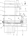
- 1 shows a support profile (support tube) of a tail lift that runs transversely to the longitudinal direction of a vehicle.
- connection plates 2 , 3 , 4 which stand backwards in the longitudinal direction of the vehicle, as bearing points for support arms 5 supporting a platform or for lifting cylinders 6 and tilt cylinders 7 controlling the lifting and lowering movements, and their pivot axis 8 or 9 are each shown in dash-dot lines in FIG. 1.
- a rear-extending underride protection bracket 10 is fastened further inside on the support profile 1 in a manner not shown.
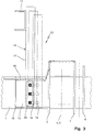
- the support profile 1 of the tail lift is attached to the chassis frame 11 (FIG. 3) by means of a suspension device 12 , which is essentially provided by a connecting arm 13 on the rear side and a counter bearing on the front side of the support profile 1 and by a connecting arm 13 on the chassis frame 11 fixing U-shaped suspension plate 14 is formed.
- the connecting arm 13 is formed by the rear end of the inner connection plate 2 which is bent through 90 ° to the underrun protection bracket 10 and is fastened to the underrun protection bracket 10 in a manner not shown.
- the two side surfaces 13a and 13b of the connecting arm are flat, vertical contact surfaces which run parallel to the longitudinal direction of the support profile 1.
- the connecting arm 13 is provided at the top with a bevel 15 bent backwards by 90 °.
- three mutually arranged holes 16 are provided in the connecting arm 13.
- the outer leg 18a abutting the inner contact surface 13a of the connecting arm 13 is fastened via three screw connections 19 which pass through the holes 16, a plate 20 serving as a washer on the outer contact surface 13b for all three screw connections 19 which absorb the tensile forces.
- the compressive forces are introduced from the support profile 1 into the suspension plate 14 via its contact surface 24.
- the fixation of the outer leg 18b is formed by a welded to the support profile 1, parallel to the longitudinal direction of the support profile 1 and outwardly open C-profile 22 (Halfen rail), which is screwed onto the outer leg 18b (screw connection 21 ), so that the outer leg can be fixed on the entire possible adjustment width of the suspension plate.
- the screw connection 21 for absorbing the compressive forces is designed to be smaller than the screw connection 19.
- the connecting arm 13 has a width of about 150 mm, so that by arranging the three arranged one below the other Holes 16 in connecting arm 13 the suspension device 12 on the different frame widths from 750-920 mm can be set as in Fig. 3 for the right side of the chassis frame 11 is indicated by dash-dotted lines.
- the holes 16 can be designed as elongated holes, such as is indicated in Fig. 3 for the left row of holes, e.g. to cover the most common chassis frame widths from 848-865 mm. On the back there is even the C-profile 22 given the entire offset width. Will a measure outside of that Main range 848-865 mm desired, the vehicle manufacturer just drill three new holes 16 on the connecting arm 13, like is indicated by the right row of holes in Fig. 3.
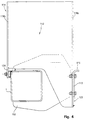
- a second embodiment of a suspension device 112 is shown, in which the same function is present, but the forces are introduced into the connecting arm 113 of the inner connecting plate 102 via a stop 123 which is welded to the outer leg 118a abutting the connecting arm 113 and the Reaches under connecting arm 113.
- the connecting arm 113 for absorbing greater forces is provided with a bevel 115 , on the one hand to achieve greater stability against the operating forces and on the other hand to be able to introduce forces acting on the underrun protection via the connecting arm 113 into the suspension plate 114 .
- the suspension plate 114 does not rest directly on the support profile 1, but rather via a stop 124 welded to its outer leg 118b .
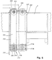
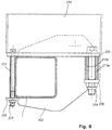
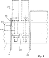
- the figures 5 to 7 show a third embodiment of a suspension device 212 , which is essentially formed by an inner and outer connecting arm 213a , 213b , a counter bearing and by a U-shaped suspension plate 214 with a bottom flange 225 .
- This suspension plate 214 is welded onto the bottom flange 225, which rests on the support profile 1.
- the two connecting arms 213a, 213b are two spaced vertical plates which run parallel to the supporting profile 1 and which are welded to both the inner connecting plate 202 and the underrun protection bracket 210 and form screw bearing webs, between which a channel-shaped screw pocket 226 is defined.
- a screw pocket 228 is likewise formed on the opposite side of the support profile 1 by means of a screw bearing web 227 .
- the bottom flange 225 also lies in the tension area on the two connecting arms 213a, 213b and in the pressure area on the screw bearing web 227.
- the support profile 1 is fastened to the base flange 225 both by means of a screw connection 219 extending through the screw pocket 226 and by means of a lower clamping plate 220 and also by means of a screw connection 221 extending through the screw pocket 228 and by means of a lower clamping plate 229 .
- the suspension plate 214 can be moved and adjusted between its innermost position (solid line) and its outermost position (dash-dotted line) in accordance with the chassis frame width (for example 750-920 mm) in the longitudinal direction of the support profile 1.
- the suspension plate 14, 114, 214 is preferably in each case possible arranged close to the inner connection plate 2, 202, thus as large a part as possible on the inner connection plate 2, 202 forces acting directly in the suspension plate 14, 114, 214 and not introduced into the support profile 1 can.
- the connecting arm 13, 113 or the Connection arms 213a, 213b formed correspondingly wide be so that the suspension plate 14, 114, 214 is always in the outer half of the connecting arm 13, 113 and the connecting arms 213a, 213b.
Landscapes
- Engineering & Computer Science (AREA)
- Transportation (AREA)
- Mechanical Engineering (AREA)
- Vehicle Body Suspensions (AREA)
- Body Structure For Vehicles (AREA)
Applications Claiming Priority (2)
| Application Number | Priority Date | Filing Date | Title |
|---|---|---|---|
| DE19741456A DE19741456C1 (de) | 1997-09-19 | 1997-09-19 | Aufhängevorrichtung für eine an einem Fahrzeug angebrachte Hubladebühne |
| DE19741456 | 1997-09-19 |
Publications (3)
| Publication Number | Publication Date |
|---|---|
| EP0903261A2 true EP0903261A2 (fr) | 1999-03-24 |
| EP0903261A3 EP0903261A3 (fr) | 1999-04-14 |
| EP0903261B1 EP0903261B1 (fr) | 2001-11-28 |
Family
ID=7842995
Family Applications (1)
| Application Number | Title | Priority Date | Filing Date |
|---|---|---|---|
| EP98114566A Expired - Lifetime EP0903261B1 (fr) | 1997-09-19 | 1998-08-03 | Dispositif de suspension pour un hayon élévateur |
Country Status (3)
| Country | Link |
|---|---|
| EP (1) | EP0903261B1 (fr) |
| DE (2) | DE19741456C1 (fr) |
| PL (1) | PL189445B1 (fr) |
Cited By (2)
| Publication number | Priority date | Publication date | Assignee | Title |
|---|---|---|---|---|
| WO2015088914A1 (fr) * | 2013-12-10 | 2015-06-18 | Maxon Industries, Inc. | Système de montage pour anti-encastrement de véhicule |
| US10875482B2 (en) | 2013-12-10 | 2020-12-29 | Maxon Industries, Inc. | Mounting system for vehicle underride |
Citations (1)
| Publication number | Priority date | Publication date | Assignee | Title |
|---|---|---|---|---|
| DE3302681C2 (fr) | 1983-01-27 | 1990-12-20 | Gerd 7100 Heilbronn De Baer |
Family Cites Families (3)
| Publication number | Priority date | Publication date | Assignee | Title |
|---|---|---|---|---|
| FR2604665B1 (fr) * | 1986-10-02 | 1988-12-02 | Mic Sa | Dispositif de support de hayon elevateur pour vehicule de transport routier |
| DE4114705C2 (de) * | 1991-05-06 | 1997-03-06 | Baer Gerd Gmbh | Aufhängevorrichtung für Tragrohre von Ladebordwänden an Fahrzeugen |
| DE19617996C2 (de) * | 1996-05-04 | 2000-08-31 | Gerd Baer | Befestigungsvorrichtung für eine Hubladebühne |
-
1997
- 1997-09-19 DE DE19741456A patent/DE19741456C1/de not_active Expired - Fee Related
-
1998
- 1998-08-03 DE DE59802220T patent/DE59802220D1/de not_active Expired - Lifetime
- 1998-08-03 EP EP98114566A patent/EP0903261B1/fr not_active Expired - Lifetime
- 1998-08-20 PL PL98328119A patent/PL189445B1/pl not_active IP Right Cessation
Patent Citations (1)
| Publication number | Priority date | Publication date | Assignee | Title |
|---|---|---|---|---|
| DE3302681C2 (fr) | 1983-01-27 | 1990-12-20 | Gerd 7100 Heilbronn De Baer |
Cited By (3)
| Publication number | Priority date | Publication date | Assignee | Title |
|---|---|---|---|---|
| WO2015088914A1 (fr) * | 2013-12-10 | 2015-06-18 | Maxon Industries, Inc. | Système de montage pour anti-encastrement de véhicule |
| US10220759B2 (en) | 2013-12-10 | 2019-03-05 | Maxon Industries, Inc. | Mounting system for vehicle underride |
| US10875482B2 (en) | 2013-12-10 | 2020-12-29 | Maxon Industries, Inc. | Mounting system for vehicle underride |
Also Published As
| Publication number | Publication date |
|---|---|
| PL328119A1 (en) | 1999-03-29 |
| EP0903261A3 (fr) | 1999-04-14 |
| DE19741456C1 (de) | 1999-01-07 |
| EP0903261B1 (fr) | 2001-11-28 |
| DE59802220D1 (de) | 2002-01-10 |
| PL189445B1 (pl) | 2005-08-31 |
Similar Documents
| Publication | Publication Date | Title |
|---|---|---|
| DE69423972T2 (de) | Endabschnitt eines rahmenteils für ein fahrzeug | |
| DE2836889C2 (de) | Auslegerabschnitt für einen Teleskopkranausleger | |
| DE3704598A1 (de) | Bewegliches geruest | |
| DE29800368U1 (de) | Geschraubter Hilfsrahmen | |
| DE60119126T2 (de) | Vorrichtung zum festklemmen und transportieren flacher güter | |
| EP2818362B1 (fr) | Plate-forme de chargement par levage | |
| EP0918036B1 (fr) | Dispositif pour suspendre un rail, en particulier un rail creux ouvert vert le bas d'une grue suspendue | |
| DE202017007410U1 (de) | Vorrichtung zur kraft- und/oder formschlüssigen Befestigung eines Bauteils an einem Fahrzeugrahmen | |
| DE602005005662T2 (de) | Frontstruktur eines kraftfahrzeuges | |
| EP0903261B1 (fr) | Dispositif de suspension pour un hayon élévateur | |
| DE2645964A1 (de) | Plattenfilterpresse mit haengend angeordneten filterplatten | |
| EP0955263A2 (fr) | Limitation de course pour mécanismes de translation, en particulier de dispositifs de levage | |
| DE10143591B4 (de) | Hubladebühnenvorrichtung | |
| DE3611136A1 (de) | Klemmhalterung | |
| CH620817A5 (en) | Connection of a shelf to a vertical support element in shelf units | |
| EP0473075B1 (fr) | Châssis pour une remorque de transport | |
| WO1987004982A1 (fr) | Fixation pour galerie porte-bagages | |
| DE60114689T2 (de) | Kabelkanal und dafür geeignete Klemmschelle | |
| DE10206476A1 (de) | Versteifungsstruktur an Kraftfahrzeugen, insbesondere Heckversteifungsstruktur | |
| DE29912906U1 (de) | Klemmhalterung | |
| EP0805069A1 (fr) | Dispositif d'assemblage pour un hayon élévatrice | |
| DE19935778B4 (de) | Deichselanordnung | |
| EP1291265A2 (fr) | Poutre de chassis de véhicule et chassis de véhicule | |
| DE2833953A1 (de) | Vorrichtung zur verringerung des luftwiderstandes eines lastkraftwagens | |
| DE102022116226A1 (de) | Seitenprofil für eine Fördervorrichtung |
Legal Events
| Date | Code | Title | Description |
|---|---|---|---|
| PUAI | Public reference made under article 153(3) epc to a published international application that has entered the european phase |
Free format text: ORIGINAL CODE: 0009012 |
|
| PUAL | Search report despatched |
Free format text: ORIGINAL CODE: 0009013 |
|
| AK | Designated contracting states |
Kind code of ref document: A2 Designated state(s): DE FR GB NL |
|
| AX | Request for extension of the european patent |
Free format text: AL;LT;LV;MK;RO;SI |
|
| AK | Designated contracting states |
Kind code of ref document: A3 Designated state(s): AT BE CH CY DE DK ES FI FR GB GR IE IT LI LU MC NL PT SE |
|
| AX | Request for extension of the european patent |
Free format text: AL;LT;LV;MK;RO;SI |
|
| 17P | Request for examination filed |
Effective date: 19990324 |
|
| AKX | Designation fees paid |
Free format text: DE FR GB NL |
|
| 17Q | First examination report despatched |
Effective date: 20000209 |
|
| GRAG | Despatch of communication of intention to grant |
Free format text: ORIGINAL CODE: EPIDOS AGRA |
|
| GRAG | Despatch of communication of intention to grant |
Free format text: ORIGINAL CODE: EPIDOS AGRA |
|
| GRAH | Despatch of communication of intention to grant a patent |
Free format text: ORIGINAL CODE: EPIDOS IGRA |
|
| GRAH | Despatch of communication of intention to grant a patent |
Free format text: ORIGINAL CODE: EPIDOS IGRA |
|
| GRAA | (expected) grant |
Free format text: ORIGINAL CODE: 0009210 |
|
| AK | Designated contracting states |
Kind code of ref document: B1 Designated state(s): DE FR GB NL |
|
| GBT | Gb: translation of ep patent filed (gb section 77(6)(a)/1977) |
Effective date: 20011128 |
|
| REG | Reference to a national code |
Ref country code: GB Ref legal event code: IF02 |
|
| REF | Corresponds to: |
Ref document number: 59802220 Country of ref document: DE Date of ref document: 20020110 |
|
| ET | Fr: translation filed | ||
| PLBE | No opposition filed within time limit |
Free format text: ORIGINAL CODE: 0009261 |
|
| STAA | Information on the status of an ep patent application or granted ep patent |
Free format text: STATUS: NO OPPOSITION FILED WITHIN TIME LIMIT |
|
| 26N | No opposition filed | ||
| PGFP | Annual fee paid to national office [announced via postgrant information from national office to epo] |
Ref country code: GB Payment date: 20070710 Year of fee payment: 10 |
|
| PGFP | Annual fee paid to national office [announced via postgrant information from national office to epo] |
Ref country code: NL Payment date: 20070820 Year of fee payment: 10 |
|
| GBPC | Gb: european patent ceased through non-payment of renewal fee |
Effective date: 20080803 |
|
| PGFP | Annual fee paid to national office [announced via postgrant information from national office to epo] |
Ref country code: FR Payment date: 20081021 Year of fee payment: 11 |
|
| NLV4 | Nl: lapsed or anulled due to non-payment of the annual fee |
Effective date: 20090301 |
|
| PG25 | Lapsed in a contracting state [announced via postgrant information from national office to epo] |
Ref country code: NL Free format text: LAPSE BECAUSE OF NON-PAYMENT OF DUE FEES Effective date: 20090301 |
|
| PG25 | Lapsed in a contracting state [announced via postgrant information from national office to epo] |
Ref country code: GB Free format text: LAPSE BECAUSE OF NON-PAYMENT OF DUE FEES Effective date: 20080803 |
|
| REG | Reference to a national code |
Ref country code: FR Ref legal event code: ST Effective date: 20100430 |
|
| PG25 | Lapsed in a contracting state [announced via postgrant information from national office to epo] |
Ref country code: FR Free format text: LAPSE BECAUSE OF NON-PAYMENT OF DUE FEES Effective date: 20090831 |
|
| PGFP | Annual fee paid to national office [announced via postgrant information from national office to epo] |
Ref country code: DE Payment date: 20171024 Year of fee payment: 20 |
|
| REG | Reference to a national code |
Ref country code: DE Ref legal event code: R071 Ref document number: 59802220 Country of ref document: DE |