EP0903454A2 - Fahrzeugtürgriff - Google Patents
Fahrzeugtürgriff Download PDFInfo
- Publication number
- EP0903454A2 EP0903454A2 EP98117948A EP98117948A EP0903454A2 EP 0903454 A2 EP0903454 A2 EP 0903454A2 EP 98117948 A EP98117948 A EP 98117948A EP 98117948 A EP98117948 A EP 98117948A EP 0903454 A2 EP0903454 A2 EP 0903454A2
- Authority
- EP
- European Patent Office
- Prior art keywords
- handle
- pushbutton switch
- carried
- switching body
- seat
- Prior art date
- Legal status (The legal status is an assumption and is not a legal conclusion. Google has not performed a legal analysis and makes no representation as to the accuracy of the status listed.)
- Withdrawn
Links
Images

Classifications
-
- E—FIXED CONSTRUCTIONS
- E05—LOCKS; KEYS; WINDOW OR DOOR FITTINGS; SAFES
- E05B—LOCKS; ACCESSORIES THEREFOR; HANDCUFFS
- E05B85/00—Details of vehicle locks not provided for in groups E05B77/00 - E05B83/00
- E05B85/10—Handles
-
- E—FIXED CONSTRUCTIONS
- E05—LOCKS; KEYS; WINDOW OR DOOR FITTINGS; SAFES
- E05B—LOCKS; ACCESSORIES THEREFOR; HANDCUFFS
- E05B81/00—Power-actuated vehicle locks
- E05B81/54—Electrical circuits
- E05B81/64—Monitoring or sensing, e.g. by using switches or sensors
- E05B81/76—Detection of handle operation; Detection of a user approaching a handle; Electrical switching actions performed by door handles
Definitions
- the present invention relates to a vehicle door handle.
- the present invention relates in particular, but not exclusively, to a handle for a vehicle luggage compartment door, and of the type comprising a rigid structure fitted to the vehicle door and supporting a device for controlling an electric door lock.
- Known control devices normally comprise a pushbutton switch; and a push element fitted in sliding manner to the rigid structure, and which is moved manually by the user into a forward switching position to activate the pushbutton switch, and is maintained in a withdrawn rest position detached from the pushbutton switch by one or more elastic reaction elements compressed between the push element and the structure.
- a handle for a vehicle door having at least one electric lock; the handle comprising a structure fitted to the door, and at least one device, carried by said structure, for manually controlling said electric lock; the device comprising a pushbutton switch, and manual operating means for manually operating the pushbutton switch; characterized in that said manual operating means comprise a single rocker-arm switching body having a first portion acting directly on said pushbutton switch, and hinge-connecting means for connecting an intermediate second portion of said switching body to said structure in rotary manner about a hinge axis; elastic means being provided to maintain said switching body in a rotated rest position in which said first portion is detached from said pushbutton switch.
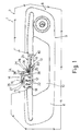
- Number 1 in Figures 1 and 3 indicates as a whole a vehicle door, the body 2 of which comprises a hollow portion 3 defining a cavity 4 ( Figure 3), which communicates externally through a first opening 5, and with the inside of door 1 through an elongated second opening 6.
- Door 1 is fitted in known manner (not described in detail) with a handle 8 comprising a structure 9, a flared hollow portion 10 of which extends inside cavity 4 through opening 5, and a peripheral flange portion 11 of which extends outside body 2 to close the gap defined by portions 3 and 10.
- Portion 10 comprises a flat lateral wall 12, which faces the portion of body 2 having opening 6, in turn comprises an elongated opening 13, and forms part of a device 14 for controlling a known electric lock (not shown) of door 1.
- device 14 comprises a known pushbutton switch 15, which, in use, is located inside door 1 and has a respective axis 16 perpendicular to wall 12.
- Switch 15 is fitted to a bracket 18, which is integral with wall 12, extends inside door 1 through opening 6, and defines a click-in seat 19 for switch 15, which is clicked into seat 19 through a lateral opening 20 in seat 19.
- Inside seat 19, switch 15 is maintained in a fixed position by a pair- of parallel pins 22 ( Figures 1 and 2), which extend inside seat 19 perpendicularly to axis 16, and each engage a respective through hole 23 in switch 15.
- switch 15 is activated manually from outside structure 9 by means of an elongated rocker-arm body 24, which is formed in one piece, preferably molded from plastic material, and comprises two opposite end portions 25 and 26 : portion 25 extends to substantially close opening 13, while portion 26 directly contacts a movable element 27 of switch 15.
- Elongated body 24 also comprises an intermediate portion 28, which is hinged to a portion of wall 12 extending between bracket 18 and opening 13 to rotate about a hinge axis 29 parallel to wall 12 and perpendicular to axis 16.
- wall 12 carries, integrally, a pair of platelike elastic appendixes 31, which extend, perpendicularly to wall 12, inside door 1 through opening 6, are positioned facing each other to define a fork 32, and have respective through holes 33 (Figure 2) coaxial with axis 29.
- Intermediate portion 28 extends inside fork 32, and carries, integrally, a pair of opposite outer pins 35 coaxial with axis 29 and defined by respective axial surfaces 36 converging with each other and with wall 12 ( Figure 3).
- surfaces 36 cooperate in sliding manner with respective inclined lead-in surfaces internally defining the free ends of appendixes 31 to slightly flex appendixes 31 and permit each pin 35 to click inside respective hole 33.
- body 24 is maintained in a rest position - in which, portion 26 is detached from movable element 27 of switch 15 - by a pin-type wire torsion spring 36 inside intermediate portion 28.
- Spring 36 comprises a central portion 37 wound about a pair of pins 38 extending coaxially with axis 29 inside intermediate portion 28; and two opposite end arms, one of which contacts portion 25, and the other of which contacts a fixed stop 39 integral with wall 12.
- Stop 39 also defines an angular stop for limiting rotation of body 24 about axis 29 when body 24 is rotated by pressure applied by the user.
- opening 14 is closed externally by a seal 40 made of elastomeric material, extending on the opposite side of wall 12 to body 24, and comprising two opposite projections 41 and 42 ( Figures 3 and 4) : projection 41 projects outwards; while projection 42 loosely engages opening 13 and rests against portion 25 of body 24.
- seal 40 also comprises a substantially flat portion 43 extending in contact with an outer surface of wall 12, and is maintained contacting said surface by a number of appendixes 44 integral with seal 40, and which engage respective slots 45 formed in wall 12 to click onto the other side of wall 12.
- handle 8 as described is therefore extremely straightforward in design, quick to assemble, and cheap to produce. This is mainly due to the straightforward design of the lock components, and to the lock being assembled by simply fitting portion 37 of- spring 36 onto pins 38 of body 24, and clicking the resulting body-spring assembly onto structure 9 by pushing portion 28 of the body between the arms of fork 32, after first clicking switch 15 onto bracket 18 and seal 40 onto structure 9.
- seal 40 to structure 9 provides for fluidtight sealing opening 13 in structure 9, through which the inside of door 1 communicates externally, and so forming a control device unaffected by external agents.
- seal 40 - in particular the provision of projection 41 - enables rapid location by the user of the portion to be pressed to activate the lock.
- wall 12 may be fitted with two devices 14, each for controlling a respective lock.
- This solution is particularly advantageous in the event door 1 comprises two electric locks : one interposed between body 2 of door 1 and the vehicle frame, and the other between body 2 and the window of door 1.
- body 24 may be formed differently from the one described and illustrated herein by way of example, and may be maintained in the rest position by elastic elements other than the one shown and, for example, by elastic appendixes integral with or fitted to body 24.
Landscapes
- Lock And Its Accessories (AREA)
Applications Claiming Priority (2)
| Application Number | Priority Date | Filing Date | Title |
|---|---|---|---|
| ITTO970835 IT1294882B1 (it) | 1997-09-23 | 1997-09-23 | Maniglia per una porta di un veicolo. |
| ITTO970835 | 1997-09-23 |
Publications (2)
| Publication Number | Publication Date |
|---|---|
| EP0903454A2 true EP0903454A2 (de) | 1999-03-24 |
| EP0903454A3 EP0903454A3 (de) | 1999-09-08 |
Family
ID=11416015
Family Applications (1)
| Application Number | Title | Priority Date | Filing Date |
|---|---|---|---|
| EP98117948A Withdrawn EP0903454A3 (de) | 1997-09-23 | 1998-09-22 | Fahrzeugtürgriff |
Country Status (2)
| Country | Link |
|---|---|
| EP (1) | EP0903454A3 (de) |
| IT (1) | IT1294882B1 (de) |
Cited By (8)
| Publication number | Priority date | Publication date | Assignee | Title |
|---|---|---|---|---|
| ES2166658A1 (es) * | 1999-04-23 | 2002-04-16 | Valeo Sist S De Seguridad S A | Manecilla para puerta de vehiculo con apertura del pestillo por microrruptor. |
| EP1128002A3 (de) * | 2000-02-23 | 2002-06-05 | Valeo Sicurezza Abitacolo S.p.A. | Türgriff für ein Kraftfahrzeug |
| EP1329573A3 (de) * | 2001-11-15 | 2005-06-15 | Plastal S.p.A. | Elektromechanischer Griff für das Öffnen einer Heckklappe od. dgl. eines Kraftfahrzeugs |
| FR2865708A1 (fr) * | 2004-01-29 | 2005-08-05 | Neyr Plastiques Holding | Module de commande d'un ouvrant de vehicule. |
| EP1803595A1 (de) * | 2005-12-28 | 2007-07-04 | HONDA MOTOR CO., Ltd. | Türstruktur für ein Kraftfahrzeug |
| WO2012097791A1 (de) * | 2010-12-21 | 2012-07-26 | Huf Hülsbeck & Fürst Gmbh & Co. Kg | Gehäuse für einen tastschalter |
| CN114541895A (zh) * | 2022-03-23 | 2022-05-27 | 上海汽车集团股份有限公司 | 一种外门把手、车辆以及外门把手的装配方法 |
| EP4108873A1 (de) * | 2021-06-24 | 2022-12-28 | U-Shin France | Fahrzeugtürgriffanordnung |
Family Cites Families (5)
| Publication number | Priority date | Publication date | Assignee | Title |
|---|---|---|---|---|
| DE1093697B (de) * | 1956-10-01 | 1960-11-24 | Daimler Benz Ag | Tuerschloss fuer Kraftfahrzeugtueren, insbesondere Zapfenschloss |
| FR2654767B1 (fr) * | 1989-11-17 | 1995-02-10 | Vachette Sa | Mecanisme de commande d'ouverture d'une portiere de vehicule automobile et portiere le comportant. |
| FR2724686B1 (fr) * | 1994-09-20 | 1999-01-22 | Peugeot | Dispositif d'ouverture electrique par pression d'une porte de vehicule automobile |
| JPH09250265A (ja) * | 1996-01-10 | 1997-09-22 | Tokai Rika Co Ltd | 車両用ドアロック解除装置 |
| FR2753739B1 (fr) * | 1996-09-20 | 1998-10-23 | Poignee de commande de l'ouverture d'une serrure d'un ouvrant de vehicule automobile |
-
1997
- 1997-09-23 IT ITTO970835 patent/IT1294882B1/it active IP Right Grant
-
1998
- 1998-09-22 EP EP98117948A patent/EP0903454A3/de not_active Withdrawn
Cited By (12)
| Publication number | Priority date | Publication date | Assignee | Title |
|---|---|---|---|---|
| ES2166658A1 (es) * | 1999-04-23 | 2002-04-16 | Valeo Sist S De Seguridad S A | Manecilla para puerta de vehiculo con apertura del pestillo por microrruptor. |
| EP1128002A3 (de) * | 2000-02-23 | 2002-06-05 | Valeo Sicurezza Abitacolo S.p.A. | Türgriff für ein Kraftfahrzeug |
| EP1329573A3 (de) * | 2001-11-15 | 2005-06-15 | Plastal S.p.A. | Elektromechanischer Griff für das Öffnen einer Heckklappe od. dgl. eines Kraftfahrzeugs |
| FR2865708A1 (fr) * | 2004-01-29 | 2005-08-05 | Neyr Plastiques Holding | Module de commande d'un ouvrant de vehicule. |
| EP1803595A1 (de) * | 2005-12-28 | 2007-07-04 | HONDA MOTOR CO., Ltd. | Türstruktur für ein Kraftfahrzeug |
| WO2012097791A1 (de) * | 2010-12-21 | 2012-07-26 | Huf Hülsbeck & Fürst Gmbh & Co. Kg | Gehäuse für einen tastschalter |
| CN103380470A (zh) * | 2010-12-21 | 2013-10-30 | 胡夫·许尔斯贝克和福斯特有限及两合公司 | 用于按键开关的壳体 |
| CN103380470B (zh) * | 2010-12-21 | 2016-08-31 | 胡夫·许尔斯贝克和福斯特有限及两合公司 | 用于按键开关的壳体 |
| EP4108873A1 (de) * | 2021-06-24 | 2022-12-28 | U-Shin France | Fahrzeugtürgriffanordnung |
| WO2022268634A1 (en) * | 2021-06-24 | 2022-12-29 | U-Shin France | Vehicle door handle assembly |
| CN114541895A (zh) * | 2022-03-23 | 2022-05-27 | 上海汽车集团股份有限公司 | 一种外门把手、车辆以及外门把手的装配方法 |
| CN114541895B (zh) * | 2022-03-23 | 2023-09-01 | 上海汽车集团股份有限公司 | 一种外门把手、车辆以及外门把手的装配方法 |
Also Published As
| Publication number | Publication date |
|---|---|
| EP0903454A3 (de) | 1999-09-08 |
| IT1294882B1 (it) | 1999-04-23 |
| ITTO970835A1 (it) | 1999-03-23 |
Similar Documents
| Publication | Publication Date | Title |
|---|---|---|
| US12098578B2 (en) | Door leaf handle device, in particular for vehicle | |
| US6602077B2 (en) | Handle assembly for motor-vehicle door latch | |
| US11603683B2 (en) | Lid opening and closing device for vehicle | |
| CN110891818A (zh) | 车辆的盖装置 | |
| WO2019147544A1 (en) | Door handle assembly | |
| CN102472051B (zh) | 车门的外把手装置 | |
| US6568719B2 (en) | Door opening device, in particular for an electric household appliance door | |
| US11668118B2 (en) | Door handle device for vehicle | |
| EP1031683B1 (de) | Türgriff für Kraftfahrzeug | |
| EP1568053B1 (de) | Schalter zum öffnen von türen oder kofferraumdeckeln von kraftfahrzeugen | |
| KR100463320B1 (ko) | 와이퍼블레이드와그제조방법 | |
| EP3536883B1 (de) | Fahrzeuginnengriffvorrichtung | |
| EP1128002A2 (de) | Türgriff für ein Kraftfahrzeug | |
| EP0903453A2 (de) | Türgriff für Kraftfahrzeuge | |
| ITTO970835A1 (it) | Maniglia per una porta di un veicolo. | |
| KR100535505B1 (ko) | 차량 도어 인사이드 핸들 로드의 압축 코일 스프링 적용구조 | |
| CN210122104U (zh) | 刮片和刮水器 | |
| EP0554839B1 (de) | Einrichtung zum Bedienen der Seitenfenster von Motorfahrzeugen | |
| US11242701B2 (en) | Vehicle door lock device | |
| EP0905728A2 (de) | Vorrichtung zur Steuerung eines elektrisches Türschlosses für Kraftfahrzeuge | |
| KR200244551Y1 (ko) | 자동차의 연료 주입구 도어 | |
| KR20070064966A (ko) | 차량의 연료도어구조 | |
| JP2000345743A (ja) | 車両用ドアハンドル装置 | |
| CN110938972B (zh) | 辅助开关门装置 | |
| KR100836926B1 (ko) | 자동차의 쿼터 스위빌 글라스 개폐장치 |
Legal Events
| Date | Code | Title | Description |
|---|---|---|---|
| PUAI | Public reference made under article 153(3) epc to a published international application that has entered the european phase |
Free format text: ORIGINAL CODE: 0009012 |
|
| AK | Designated contracting states |
Kind code of ref document: A2 Designated state(s): DE ES FR GB |
|
| AX | Request for extension of the european patent |
Free format text: AL;LT;LV;MK;RO;SI |
|
| PUAL | Search report despatched |
Free format text: ORIGINAL CODE: 0009013 |
|
| AK | Designated contracting states |
Kind code of ref document: A3 Designated state(s): AT BE CH CY DE DK ES FI FR GB GR IE IT LI LU MC NL PT SE |
|
| AX | Request for extension of the european patent |
Free format text: AL;LT;LV;MK;RO;SI |
|
| 17P | Request for examination filed |
Effective date: 20000225 |
|
| AKX | Designation fees paid |
Free format text: DE ES FR GB |
|
| 17Q | First examination report despatched |
Effective date: 20020705 |
|
| STAA | Information on the status of an ep patent application or granted ep patent |
Free format text: STATUS: THE APPLICATION IS DEEMED TO BE WITHDRAWN |
|
| 18D | Application deemed to be withdrawn |
Effective date: 20021116 |