EP0903688B1 - Radiofrequenzsignaldetektor für kontaktlose IC-Karte - Google Patents
Radiofrequenzsignaldetektor für kontaktlose IC-Karte Download PDFInfo
- Publication number
- EP0903688B1 EP0903688B1 EP98402303A EP98402303A EP0903688B1 EP 0903688 B1 EP0903688 B1 EP 0903688B1 EP 98402303 A EP98402303 A EP 98402303A EP 98402303 A EP98402303 A EP 98402303A EP 0903688 B1 EP0903688 B1 EP 0903688B1
- Authority
- EP
- European Patent Office
- Prior art keywords
- circuit
- detector
- phase
- output terminal
- signals
- Prior art date
- Legal status (The legal status is an assumption and is not a legal conclusion. Google has not performed a legal analysis and makes no representation as to the accuracy of the status listed.)
- Expired - Lifetime
Links
Images

Classifications
-
- G—PHYSICS
- G06—COMPUTING OR CALCULATING; COUNTING
- G06K—GRAPHICAL DATA READING; PRESENTATION OF DATA; RECORD CARRIERS; HANDLING RECORD CARRIERS
- G06K19/00—Record carriers for use with machines and with at least a part designed to carry digital markings
- G06K19/06—Record carriers for use with machines and with at least a part designed to carry digital markings characterised by the kind of the digital marking, e.g. shape, nature, code
- G06K19/067—Record carriers with conductive marks, printed circuits or semiconductor circuit elements, e.g. credit or identity cards also with resonating or responding marks without active components
- G06K19/07—Record carriers with conductive marks, printed circuits or semiconductor circuit elements, e.g. credit or identity cards also with resonating or responding marks without active components with integrated circuit chips
- G06K19/0723—Record carriers with conductive marks, printed circuits or semiconductor circuit elements, e.g. credit or identity cards also with resonating or responding marks without active components with integrated circuit chips the record carrier comprising an arrangement for non-contact communication, e.g. wireless communication circuits on transponder cards, non-contact smart cards or RFIDs
Definitions
- the invention relates to contactless smart cards in which the transmission of the binary data between the user device and the card is carried out at radio frequency and, more particularly, in such cards, a circuit for detecting such a transmission. in radiofrequency so as to accurately determine that it is such a type of transmission.
- Such smart cards work properly only if they recognize very quickly and with certainty that the user device communicates via radio frequency signals so as to get into the operating mode adapted to this type of signals.
- the comparator circuit 16 provides on its output terminal a V RF signal indicating the presence of radio frequency signals in binary amplitude modulation. It is this V RF signal which indicates to the microcontroller 50 that the signal transmitted to the card is of the radiofrequency type.
- EP-A-0 791 706 discloses a rectifying circuit. It comprises first and second transistors forming a first pair of transistors minimizing the voltage drop between the ground and the transponder substrate. Third and fourth transistors form a second pair of transistors minimizing the voltage drop between the maximum amplitude of the AC voltage and the output voltage of the rectifier circuit. The pairs of transistors are controlled by alternative input signals. A series control circuit decouples the first and second pairs of capacitive load transistors of the transponder circuit.
- the object of the invention is to provide a radio frequency signal detector for a smart card which determines with speed and certainty the presence of radiofrequency signals.
- the detector according to the invention uses the signals at the carrier frequency.
- the invention therefore relates to a radiofrequency signal presence detector for a contactless smart card according to the claims.
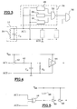
- the signals V AC1 and V AC0 can also be applied to other circuits of the smart card, in particular to a rectifying circuit 12 according to the diagram of FIG. 1 or to a circuit for generating data. the supply voltage of the smart card from the radiofrequency energy received.
- the output terminal of the circuit AND 32 may be connected directly to the microcontroller of the smart card to indicate that it is a transmission or not binary data by radio frequency or be connected to a first input terminal an AND circuit 34 whose other input terminal is connected to the output terminal of the comparator 16 of the diagram of FIG. 1.
- the phase-shift detector circuit 26 is in fact a phase opposition detector between the signals V AC1 and V AC0 which comprises (FIG. 5) an EXCLUSIVE OR 36 whose two input terminals respectively receive the signals V AC1 or V AC0 . It provides a signal when the two signals V AC1 or V AC0 are in phase opposition.
- a capacitor 38 is connected between the voltage power supply V DD and the output terminal of the circuit or EXCLUSIVE 36 to filter the effects of low amplitude phase changes between the signals V AC1 and V AC0 .
- the filtered signal is applied to a fitness circuit comprising for example two inverter circuits 46 and 48.
- the inverter circuit 40 and Schmit's Trigger are powered by the supply voltage V DD .
- the purpose of the inverting circuit is to transform the signal at the carrier frequency f into a square signal of amplitude V DD at the same frequency.
- the diode 42 prevents the discharge of the capacitor C 2 when the output terminal of the inverter circuit 40 is at ground potential.
- the capacitor C 2 and the resistor R 2 realize an integration circuit with discharge through the resistor R 2 .
- the voltage at the input terminal of the Schmit Trigger 44 increases as the frequency f of the signal increases. Consequently, its switching threshold and the values of the components C 2 and R 2 must be chosen so that the signals having a frequency greater than a certain value are detected and perform the switchover.
- the invention has been described with a detector comprising a phase shift detector circuit 26 and two radio frequency detectors 28 and 30 whose output signals are combined in the logic circuits 32,36.
Landscapes
- Engineering & Computer Science (AREA)
- Computer Networks & Wireless Communication (AREA)
- Computer Hardware Design (AREA)
- Microelectronics & Electronic Packaging (AREA)
- Physics & Mathematics (AREA)
- General Physics & Mathematics (AREA)
- Theoretical Computer Science (AREA)
- Near-Field Transmission Systems (AREA)
- Radar Systems Or Details Thereof (AREA)
Claims (3)
- Detektor für das Vorhandensein von Hochfrequenzsignalen für eine kontaktlose Chipkarte, mit einer Wicklung für eine Empfangsantenne (10), um die Signale mit der Trägerfrequenz f zu erfassen, die durch eine Benutzungsvorrichtung für die Chipkarte gesendet werden, und wenigstens einer Erfassungsschaltung (28, 30) für das Vorhandensein von Signalen mit der Trägerfrequenz f, deren Eingangsanschluss mit einem Ende (AC1, AC0) der Antennenwicklung (10) verbunden ist;- dadurch gekennzeichnet, dass dieser ferner umfasst:- eine Gleichrichtungs- und Filterungsschaltung (12), die an die Enden (AC1, AC0) der Antennenwicklung angeschlossen ist;- eine Schaltung (26) zur Erfassung einer Phasenverschiebung, die zwei Eingangsanschlüsse aufweist, die jeweils an die Enden (AC1, AC0) der Antennenwicklung (20) angeschlossen sind, wobei die Schaltung zur Erfassung der Phasenverschiebung auf ihrem Ausgangsanschluss ein Signal bereit stellt, wenn sich die auf den Eingangsanschlüssen vorhandenen Signale in Phasenopposition befinden, und- eine Logik-UND-Schaltung (32), die wenigstens zwei Eingangsanschlüsse aufweist, von denen einer mit dem Ausgangsanschluss der Schaltung (26) zur Erfassung einer Phasenverschiebung verbunden ist und der andere mit dem Ausgangsanschluss einer der Erfassungsschaltungen (28 oder 30) verbunden ist.
- Detektor nach Anspruch 1, dadurch gekennzeichnet, dass die Erfassungsschaltung (28 oder 30) umfasst:- eine Inverterschaltung (40), deren Eingangsanschluss mit einem Ende (AC 1, AC0) der Antennenwicklung (20) verbunden ist,- eine Diode (42), deren Anode mit dem Ausgangsanschluss der Inverterschaltung (40) verbunden ist,- eine Integrationsschaltung mit einem Kondensator (C2) und einem Widerstand (R2) in Parallele, von denen einer der gemeinsamen Punkte mit der Kathode der Diode (42) verbunden ist, und- eine Wippenschaltung (44), deren Eingangsanschluss mit der Kathode der Diode (42) verbunden ist, wobei die Wippenschaltung den Zustand ändert, wenn die Ladungsspannung, die vom Kondensator (C2) erreicht wird, größer als ein bestimmter Schwellenwert ist.
- Detektor nach Anspruch 1 oder 2, dadurch gekennzeichnet, dass die Schaltung (26) zur Erfassung einer Phasenverschiebung umfasst:- eine ODER-EXKLUSIV-Schaltung mit zwei Eingangsanschlüssen, die jeweils an die Enden (AC1, AC0) der Antennenwicklung (20) angeschlossen sind, und- einen Kondensator (38), der an den Ausgangsanschluss der ODER-EXKLUSIV-Schaltung angeschlossen ist.
Applications Claiming Priority (2)
| Application Number | Priority Date | Filing Date | Title |
|---|---|---|---|
| FR9711787A FR2768875B1 (fr) | 1997-09-23 | 1997-09-23 | Detecteur de signaux radiofrequence pour carte a puce sans contact |
| FR9711787 | 1997-09-23 |
Publications (2)
| Publication Number | Publication Date |
|---|---|
| EP0903688A1 EP0903688A1 (de) | 1999-03-24 |
| EP0903688B1 true EP0903688B1 (de) | 2006-05-24 |
Family
ID=9511349
Family Applications (1)
| Application Number | Title | Priority Date | Filing Date |
|---|---|---|---|
| EP98402303A Expired - Lifetime EP0903688B1 (de) | 1997-09-23 | 1998-09-17 | Radiofrequenzsignaldetektor für kontaktlose IC-Karte |
Country Status (5)
| Country | Link |
|---|---|
| US (1) | US6152373A (de) |
| EP (1) | EP0903688B1 (de) |
| JP (1) | JP3065586B2 (de) |
| DE (1) | DE69834607T2 (de) |
| FR (1) | FR2768875B1 (de) |
Families Citing this family (5)
| Publication number | Priority date | Publication date | Assignee | Title |
|---|---|---|---|---|
| US6837438B1 (en) * | 1998-10-30 | 2005-01-04 | Hitachi Maxell, Ltd. | Non-contact information medium and communication system utilizing the same |
| JP3824451B2 (ja) * | 1999-07-29 | 2006-09-20 | 富士通株式会社 | 非接触icカードの有無検出回路 |
| US6612852B1 (en) | 2000-04-13 | 2003-09-02 | Molex Incorporated | Contactless interconnection system |
| US6362972B1 (en) | 2000-04-13 | 2002-03-26 | Molex Incorporated | Contactless interconnection system |
| US7331979B2 (en) | 2003-06-04 | 2008-02-19 | Access Closure, Inc. | Apparatus and methods for sealing a vascular puncture |
Citations (1)
| Publication number | Priority date | Publication date | Assignee | Title |
|---|---|---|---|---|
| EP0791706A1 (de) * | 1996-01-31 | 1997-08-27 | Texas Instruments Deutschland Gmbh | Verbesserung für Vollweggleichrichter |
Family Cites Families (6)
| Publication number | Priority date | Publication date | Assignee | Title |
|---|---|---|---|---|
| US3816708A (en) * | 1973-05-25 | 1974-06-11 | Proximity Devices | Electronic recognition and identification system |
| FR2662876B1 (fr) * | 1990-05-29 | 1994-04-29 | Fontaine Sa | Recepteur d'ondes radioelectriques a boucle d'induction et a extremement faible consommation, en particulier pour telecommande. |
| US5533058A (en) * | 1994-03-10 | 1996-07-02 | Delco Electronics Corporation | Method and apparatus for low current RF signal detection |
| JPH0877318A (ja) * | 1994-09-08 | 1996-03-22 | Toshiba Corp | 非接触式情報記録媒体 |
| JPH0962816A (ja) * | 1994-10-06 | 1997-03-07 | Mitsubishi Electric Corp | 非接触icカードおよびこれを含む非接触icカードシステム |
| JP3695833B2 (ja) * | 1996-04-05 | 2005-09-14 | 株式会社ルネサステクノロジ | Pll回路 |
-
1997
- 1997-09-23 FR FR9711787A patent/FR2768875B1/fr not_active Expired - Fee Related
-
1998
- 1998-09-17 EP EP98402303A patent/EP0903688B1/de not_active Expired - Lifetime
- 1998-09-17 DE DE69834607T patent/DE69834607T2/de not_active Expired - Lifetime
- 1998-09-18 US US09/157,060 patent/US6152373A/en not_active Expired - Lifetime
- 1998-09-24 JP JP10269355A patent/JP3065586B2/ja not_active Expired - Lifetime
Patent Citations (1)
| Publication number | Priority date | Publication date | Assignee | Title |
|---|---|---|---|---|
| EP0791706A1 (de) * | 1996-01-31 | 1997-08-27 | Texas Instruments Deutschland Gmbh | Verbesserung für Vollweggleichrichter |
Also Published As
| Publication number | Publication date |
|---|---|
| DE69834607D1 (de) | 2006-06-29 |
| FR2768875A1 (fr) | 1999-03-26 |
| DE69834607T2 (de) | 2007-05-03 |
| EP0903688A1 (de) | 1999-03-24 |
| JPH11168416A (ja) | 1999-06-22 |
| US6152373A (en) | 2000-11-28 |
| JP3065586B2 (ja) | 2000-07-17 |
| FR2768875B1 (fr) | 2000-06-02 |
Similar Documents
| Publication | Publication Date | Title |
|---|---|---|
| EP0903689A1 (de) | Demodulator für kontaktlose Chipkarte | |
| US6294953B1 (en) | High sensitivity demodulator for a radio tag and method | |
| US8188787B2 (en) | Peak detector for detecting peaks in a modulated signal | |
| EP1312032B1 (de) | Hochempfindlicher leser für passive transponder | |
| JPH11174148A (ja) | 電子式識別システム | |
| EP0412884B1 (de) | Funksystem zur Datenübertragung an eine preiswerte passive Endstelle | |
| WO2007129187A1 (fr) | Procede et dispositif de transmission de donnees par modulation de charge | |
| EP3001575B1 (de) | Verfahren zur steuerung des betriebs eines objekts, das in der lage ist, ohne einen kontakt mit einem lesegerät zu kommunizieren, entsprechende vorrichtung und entsprechendes objekt | |
| EP1496470A1 (de) | Kombi-Chipkarte | |
| EP2107694A1 (de) | Endgerät zur Funksendung und zum Funkempfang durch induktive Kupplung | |
| FR2751148A1 (fr) | Demodulateur d'un signal alternatif module en amplitude recu dans une bobine par induction electromagnetique | |
| EP0903688B1 (de) | Radiofrequenzsignaldetektor für kontaktlose IC-Karte | |
| KR20010083951A (ko) | Ask-복조 방법 및 ask-복조기 | |
| EP1043679B1 (de) | Leser mit Einrichtung zur Bestimmung des Abstandes zwischen dem Leser und einem Transponder | |
| EP1269702B1 (de) | Demodulator für ein amplitudenmoduliertes alternierendes signal | |
| EP1672388B1 (de) | Elektromagnetischer Transponder ohne eigenständige Energieversorgung | |
| CA2191794C (fr) | Circuit d'alimentation et de modulation pour une etiquette interrogeable a distance | |
| EP1665573A1 (de) | Tragbares objekt mit mehrebenen-demodulation, das induktiv an eine feststation angekoppelt ist | |
| WO2004093341A1 (fr) | Dispositif et teletransmission par couplage inductif a modulation multi-niveaux | |
| KR100426303B1 (ko) | 스마트 카드 | |
| FR2835119A1 (fr) | Demodulateur a large dynamique pour cartes a puce ou etiquettes sans contact | |
| US6897719B2 (en) | Demodulation circuit and demodulation method | |
| FR2791491A1 (fr) | Telealimentation d'un transpondeur electromagnetique |
Legal Events
| Date | Code | Title | Description |
|---|---|---|---|
| PUAI | Public reference made under article 153(3) epc to a published international application that has entered the european phase |
Free format text: ORIGINAL CODE: 0009012 |
|
| AK | Designated contracting states |
Kind code of ref document: A1 Designated state(s): DE FR GB IT |
|
| AX | Request for extension of the european patent |
Free format text: AL;LT;LV;MK;RO;SI |
|
| 17P | Request for examination filed |
Effective date: 19990401 |
|
| AKX | Designation fees paid |
Free format text: DE FR GB IT |
|
| RAP1 | Party data changed (applicant data changed or rights of an application transferred) |
Owner name: STMICROELECTRONICS S.A. |
|
| 17Q | First examination report despatched |
Effective date: 20040220 |
|
| GRAP | Despatch of communication of intention to grant a patent |
Free format text: ORIGINAL CODE: EPIDOSNIGR1 |
|
| GRAS | Grant fee paid |
Free format text: ORIGINAL CODE: EPIDOSNIGR3 |
|
| GRAA | (expected) grant |
Free format text: ORIGINAL CODE: 0009210 |
|
| AK | Designated contracting states |
Kind code of ref document: B1 Designated state(s): DE FR GB IT |
|
| REG | Reference to a national code |
Ref country code: GB Ref legal event code: FG4D Free format text: NOT ENGLISH |
|
| REF | Corresponds to: |
Ref document number: 69834607 Country of ref document: DE Date of ref document: 20060629 Kind code of ref document: P |
|
| GBT | Gb: translation of ep patent filed (gb section 77(6)(a)/1977) |
Effective date: 20060822 |
|
| PLBE | No opposition filed within time limit |
Free format text: ORIGINAL CODE: 0009261 |
|
| STAA | Information on the status of an ep patent application or granted ep patent |
Free format text: STATUS: NO OPPOSITION FILED WITHIN TIME LIMIT |
|
| 26N | No opposition filed |
Effective date: 20070227 |
|
| PGFP | Annual fee paid to national office [announced via postgrant information from national office to epo] |
Ref country code: IT Payment date: 20070913 Year of fee payment: 10 |
|
| PGFP | Annual fee paid to national office [announced via postgrant information from national office to epo] |
Ref country code: GB Payment date: 20080827 Year of fee payment: 11 |
|
| PGFP | Annual fee paid to national office [announced via postgrant information from national office to epo] |
Ref country code: FR Payment date: 20080929 Year of fee payment: 11 |
|
| PG25 | Lapsed in a contracting state [announced via postgrant information from national office to epo] |
Ref country code: IT Free format text: LAPSE BECAUSE OF NON-PAYMENT OF DUE FEES Effective date: 20080917 |
|
| GBPC | Gb: european patent ceased through non-payment of renewal fee |
Effective date: 20090917 |
|
| REG | Reference to a national code |
Ref country code: FR Ref legal event code: ST Effective date: 20100531 |
|
| PG25 | Lapsed in a contracting state [announced via postgrant information from national office to epo] |
Ref country code: FR Free format text: LAPSE BECAUSE OF NON-PAYMENT OF DUE FEES Effective date: 20090930 |
|
| PG25 | Lapsed in a contracting state [announced via postgrant information from national office to epo] |
Ref country code: GB Free format text: LAPSE BECAUSE OF NON-PAYMENT OF DUE FEES Effective date: 20090917 |
|
| REG | Reference to a national code |
Ref country code: DE Ref legal event code: R082 Ref document number: 69834607 Country of ref document: DE Representative=s name: RAU, SCHNECK & HUEBNER PATENTANWAELTE RECHTSAN, DE |
|
| REG | Reference to a national code |
Ref country code: DE Ref legal event code: R082 Ref document number: 69834607 Country of ref document: DE Representative=s name: RAU, SCHNECK & HUEBNER PATENTANWAELTE RECHTSAN, DE Effective date: 20140704 Ref country code: DE Ref legal event code: R081 Ref document number: 69834607 Country of ref document: DE Owner name: MICRON TECHNOLOGY, INC., BOISE, US Free format text: FORMER OWNER: STMICROELECTRONICS S.A., MONTROUGE, FR Effective date: 20140704 |
|
| PGFP | Annual fee paid to national office [announced via postgrant information from national office to epo] |
Ref country code: DE Payment date: 20170912 Year of fee payment: 20 |
|
| REG | Reference to a national code |
Ref country code: DE Ref legal event code: R071 Ref document number: 69834607 Country of ref document: DE |