EP0903954A1 - Anordnung zur leitungsgebundenen digitalen Nachrichtenübertragung - Google Patents
Anordnung zur leitungsgebundenen digitalen Nachrichtenübertragung Download PDFInfo
- Publication number
- EP0903954A1 EP0903954A1 EP98120361A EP98120361A EP0903954A1 EP 0903954 A1 EP0903954 A1 EP 0903954A1 EP 98120361 A EP98120361 A EP 98120361A EP 98120361 A EP98120361 A EP 98120361A EP 0903954 A1 EP0903954 A1 EP 0903954A1
- Authority
- EP
- European Patent Office
- Prior art keywords
- subscriber
- tln
- evz
- transmission
- vst
- Prior art date
- Legal status (The legal status is an assumption and is not a legal conclusion. Google has not performed a legal analysis and makes no representation as to the accuracy of the status listed.)
- Withdrawn
Links
- 230000005540 biological transmission Effects 0.000 claims abstract description 46
- 238000012546 transfer Methods 0.000 claims abstract description 24
- 239000013307 optical fiber Substances 0.000 claims description 6
- 230000003287 optical effect Effects 0.000 description 8
- 239000000835 fiber Substances 0.000 description 7
- 230000008901 benefit Effects 0.000 description 3
- 238000009434 installation Methods 0.000 description 2
- RYGMFSIKBFXOCR-UHFFFAOYSA-N Copper Chemical compound [Cu] RYGMFSIKBFXOCR-UHFFFAOYSA-N 0.000 description 1
- 238000006243 chemical reaction Methods 0.000 description 1
- 229910052802 copper Inorganic materials 0.000 description 1
- 239000010949 copper Substances 0.000 description 1
- 238000010586 diagram Methods 0.000 description 1
- 239000003365 glass fiber Substances 0.000 description 1
- 239000011022 opal Substances 0.000 description 1
- 238000012797 qualification Methods 0.000 description 1
- 238000012552 review Methods 0.000 description 1
- 238000000926 separation method Methods 0.000 description 1
- 239000013589 supplement Substances 0.000 description 1
- 238000012360 testing method Methods 0.000 description 1
Images

Classifications
-
- H—ELECTRICITY
- H04—ELECTRIC COMMUNICATION TECHNIQUE
- H04Q—SELECTING
- H04Q11/00—Selecting arrangements for multiplex systems
- H04Q11/04—Selecting arrangements for multiplex systems for time-division multiplexing
- H04Q11/0421—Circuit arrangements therefor
-
- H—ELECTRICITY
- H04—ELECTRIC COMMUNICATION TECHNIQUE
- H04Q—SELECTING
- H04Q11/00—Selecting arrangements for multiplex systems
- H04Q11/0001—Selecting arrangements for multiplex systems using optical switching
-
- H—ELECTRICITY
- H04—ELECTRIC COMMUNICATION TECHNIQUE
- H04Q—SELECTING
- H04Q11/00—Selecting arrangements for multiplex systems
- H04Q11/04—Selecting arrangements for multiplex systems for time-division multiplexing
- H04Q11/0428—Integrated services digital network, i.e. systems for transmission of different types of digitised signals, e.g. speech, data, telecentral, television signals
- H04Q11/0435—Details
-
- H—ELECTRICITY
- H04—ELECTRIC COMMUNICATION TECHNIQUE
- H04Q—SELECTING
- H04Q2213/00—Indexing scheme relating to selecting arrangements in general and for multiplex systems
- H04Q2213/1301—Optical transmission, optical switches
-
- H—ELECTRICITY
- H04—ELECTRIC COMMUNICATION TECHNIQUE
- H04Q—SELECTING
- H04Q2213/00—Indexing scheme relating to selecting arrangements in general and for multiplex systems
- H04Q2213/1309—Apparatus individually associated with a subscriber line, line circuits
-
- H—ELECTRICITY
- H04—ELECTRIC COMMUNICATION TECHNIQUE
- H04Q—SELECTING
- H04Q2213/00—Indexing scheme relating to selecting arrangements in general and for multiplex systems
- H04Q2213/13096—Digital apparatus individually associated with a subscriber line, digital line circuits
-
- H—ELECTRICITY
- H04—ELECTRIC COMMUNICATION TECHNIQUE
- H04Q—SELECTING
- H04Q2213/00—Indexing scheme relating to selecting arrangements in general and for multiplex systems
- H04Q2213/13202—Network termination [NT]
-
- H—ELECTRICITY
- H04—ELECTRIC COMMUNICATION TECHNIQUE
- H04Q—SELECTING
- H04Q2213/00—Indexing scheme relating to selecting arrangements in general and for multiplex systems
- H04Q2213/13209—ISDN
-
- H—ELECTRICITY
- H04—ELECTRIC COMMUNICATION TECHNIQUE
- H04Q—SELECTING
- H04Q2213/00—Indexing scheme relating to selecting arrangements in general and for multiplex systems
- H04Q2213/13299—Bus
-
- H—ELECTRICITY
- H04—ELECTRIC COMMUNICATION TECHNIQUE
- H04Q—SELECTING
- H04Q2213/00—Indexing scheme relating to selecting arrangements in general and for multiplex systems
- H04Q2213/13386—Line concentrator
Definitions
- the invention relates to an arrangement for wired digital Message transmission between a switching center of a telecommunications network and with the same connected subscribers, with whom to switch through if necessary changing transmission rate between the switching center and an affected Participants in the digital transmission channels are switched on by means of corresponding control commands can be controlled from the switching center (U.S.-A-4,768,188).
- the digital transmission technology with its advantages over the analog technology, for example, greater range and high transmission rates, continues in the Telecommunications through more and more. It enables a wide variety of offers Services that can be used by subscribers to a telecommunications network.
- This Services today include a. Telephone, fax, telex, teletex, IDN and ISDN (basic and Primary multiplex connections). The is of particular importance Subscriber access area of the Subscribeldenetzes, so the access network.
- connection network is under the name Opal "for example in DE-Z ntz "Vol. 45 (1992), No. 11, pages 902 and 903 for a pilot project of DBP Industries.
- the light output is divided according to the number of participants Adapted lasers for light wavelengths of, for example, 1330 nm or 1550 nm must also be used.
- the respective devices of the participants are connected analogously to so-called optical network terminations , in which a digital / analog conversion takes place and in which the distribution of the transmission rate intended for each participant is switched.
- optical network terminations are not accessible to the participants. If a participant wants to make changes to the devices available on him, Anlagens If a new device is connected, then this change must be carried out by specialist personnel who have the opportunity and the qualifications to be able to carry out the necessary switching work in the optical network terminations. It is time consuming and expensive.
- connection network in which at least one optical fiber is used instead of copper cables.
- the optical fiber allows the transmission of such a large bandwidth that after the installation of a corresponding network it is no longer necessary to supplement it.
- the optical fiber runs between a central office and several access units that are in the vicinity of many participants.
- the participants are connected to the access units via suitable lines.
- the access units are line cards "with which at least one participant is connected line cards ", the participants can be connected to the central office.
- the access units - and thus also the line cards "- are not accessible to participants.
- EP-A-0 481 170 discloses a telephone system in which many telephones, in particular phones equipped with different circuits, in a simple way on broadband transmission medium can be connected.
- the invention has for its object to the arrangement described above shape that the benefits of digital messaging in the subscriber area better can be exploited.
- each participant is given the opportunity to use devices up to the maximum transmission rate of, for example, 2.56 Mbit / s
- a suitable adapter that delivers the appropriate interface signals and can be used to connect a new or additional device to the transfer point.
- the transmission rate required for this is switched through by the exchange, using an appropriate one Control commands to the channel assignments can be done in a very short time, for example during the time it takes for the subscriber to get home from the place where he bought an adapter, and specialist personnel who have to make a change on site will no longer needed.
- the digital transmission path is in this arrangement for each participant up to Transfer point extended from which the bus line starts. So the participants can Devices that require a digital interface, with the corresponding adapter in parallel connect each other to the bus line. For the connection of analogue ones Appropriate adapters with digital / analog converters are required for devices. This Implementers can also be integrated in the corresponding devices, for example in telephones be.
- the signals between the exchange and the subscribers are transmitted bidirectionally.
- the maximum transfer rate on the connected to the exchange The transmission path is, for example, 34 Mbit / s.
- the participants should have 40 Channels of 64 kbit / s each, but at least 2.56 Mbit / s, are made available.
- the Channels are assigned to the participants via the channel assignments. You are after Installation of this arrangement available to participants, but only when needed switched through.
- participant are preferably connected to the end distributors via electrical lines connected. At least one participant should be connected.
- one is connected to a switching center VST Telecommunications network connected to a fiber optic 1, which in one optical distributor OV in several LWL 2 is divided.
- a fiber optic 1 which in one optical distributor OV in several LWL 2 is divided.
- eight fiber optic cables 2 can continue from the OV. But it can also be more or less than eight FO 2.
- Fig. 1 there are four further optical fibers 2 shown.
- the fiber optic cable 1 is connected in the VST to a line termination LT.
- About LWL 1 and 2 can signals, for example, with a maximum transmission rate of 34 Mbit / s be transmitted.
- LWL 1 and 2 are routed from the VST to the EVZ terminal boxes.
- the subscribers Tln connected via electrical lines 3.
- electrical lines 3 at least two-wire lines (wire pairs) are used.
- Each of LWL 2 ends in an EVZ. He is at least one electro / optical Converter containing line termination LT connected.
- the EVZ are as active Terminal boxes equipped with active, electrically working components. You point each have a channel allocator KE to which a number of subscribers are connected. In Fig. 1 eight subscriber lines are shown for each EVZ. With every EVZ is at least a subscriber connected. It can also be more or less than eight parts. Every EVZ is in spatial proximity of at least one Tln arranged. The electrical cables run from the EVZ 3 to the parts. They can be kept short because of the spatial proximity of EVZ and parts.
- Each subscriber is - as already mentioned - with an EVZ via at least one electrical wire pair (Two-wire line) connected. Two pairs of wires are preferably used in each case. On Directional separation measures, for example echo cancellation, can then be dispensed with become.
- the electrical lines 3 each terminate at the transfer points P at which each subscriber has a digital interface at which he can connect devices up to one maximum transmission rate of 2.56 Mbit / s, for example. He needs for this purpose an adapter for each device, which was determined as the SU service unit for this device Provides interface signals. For switching and assigning the required The channel allocators KE of the EVZ are used for the transmission rate controlled from the VST.
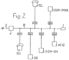
- FIG. 1 works in conjunction with FIG. 2, for example, as follows:
- one with its impedance I goes from the transfer point P of each subscriber Completed bus line B off, to which devices can be connected, which one Tln wants to operate.
- These are, for example, main telephone connections TEL, data devices DG, ISDN basic connection ISDN-BA, ISDN primary multiplex connection ISDN-PMXA and also Connections for VC12, as indicated in Fig. 2.
- the to operate these devices required transmission rates or channels are generally available at the transfer point P. Available. They only need to be switched through if necessary.
- the subscribers are initially only one connection for an analog one Have TEL.
- the TEL is via an analog adapter AA via the transfer point P as digital interface connected to the VST.
- the one implementation analog / digital Implementing adapter AA can also be integrated in the device of the TEL. For this connection is enough w. a channel with a transmission rate of 64 kbit / s. If more devices additional channels must be switched through to be connected.
- This switching is carried out via the channel assignments KE.
- the necessary one Control command is transmitted by the VST.
- a subscriber can use so many services in this way use the corresponding devices, such as those that can be tapped at the transfer point P. Number of channels or transmission rate allow it.
- the subscriber only needs one for this provided point of the network operator with an adapter suitable for the respective device to acquire the specific SU and connect it to bus line B in its premises.
- the switching of the additional channel or additional channels can take place during the time are done, which the subscriber or a corresponding person needs to after the acquisition of the adapter to get to its premises.
- the transmission of digital communications signals with an arrangement according to FIG. 1 happens for example as follows:
- the digital signals are transmitted to the EVZ via fiber optic cables 1 and 2.
- the VST and the EVZ use laser diodes as transmitters and receive diodes.
- the FO 1 and 2 are single mode fibers. It is thus ensured overall that the signals between VST and EVZ with the specified transmission rate of For example, 34 Mbit / s can be transmitted without interference. That doesn't just apply to them Distances usual in the connection network up to now. Rather, they are without the use of additional or special optical amplifiers larger distances between VST and EVZ can be bridged. The number of VSTs in a network can therefore be reduced.
- the parts are connected via the electrical lines 3 to the EVZ or their KE. Since the EVZ are installed in close proximity to at least one subscriber, it is ensured that the electrical lines 3 are so short that the digital signals with the desired maximum transmission rate of about 2.56 Mbit / s without interference between EVZ and Transfer point P can be transmitted.
- each subscriber connected to an EVZ has 40 channels provided at 64 kbit / s each. This corresponds to a transmission rate of 2.56 Mbit / s, which a subscriber could exploit to the maximum if he had a corresponding number of those offered Wants to use services.
- the subscriber must then connect his devices to his using a suitable adapter Connect the transfer point P or to the bus line B starting from the same.
- FIG. 1 has the advantage that a review of the Transmission paths and the functionality of all components or components used is possible from the EVZ with a correspondingly constructed digital transmitter. This can be done for the loop test in each case at the transfer points P of the connections Transmission routes are carried out.
Landscapes
- Engineering & Computer Science (AREA)
- Computer Networks & Wireless Communication (AREA)
- Data Exchanges In Wide-Area Networks (AREA)
- Small-Scale Networks (AREA)
- Use Of Switch Circuits For Exchanges And Methods Of Control Of Multiplex Exchanges (AREA)
- Telephonic Communication Services (AREA)
Abstract
Description
- daß der digitale Übertragungsweg für jeden Teilnehmer bis zu einem eigenen, für diesen Teilnehmer zugänglichen Übergabepunkt geführt ist,
- daß vom Übergabepunkt jedes Teilnehmers eine Busleitung ausgeht, an die unterschiedliche Geräte des Teilnehmers unter Zwischenschaltung von Adaptern parallel zueinander anschließbar sind, welche für das jeweilige Gerät bestimmte Schnittstellensignale liefern,
- daß von jedem Teilnehmer unterschiedliche Geräte mit denselben zugeordneter Übertragungsrate bis zur Ausnutzung einer am Übergabepunkt verfügbaren maximalen Übertagungsrate wahlweise und getrennt voneinander anschließbar sind,
- daß in räumlicher Nähe der Teilnehmer Endverzweiger in den Übertragungsweg eingeschaltet sind und
- daß die Kanalzuordner in den Endverzweigern angebracht sind.
Claims (3)
- Anordnung zur leitungsgebundenen digitalen Nachrichtenübertragung zwischen einer Vermittlungsstelle (VST) eines Fernmeldenetzes und mit derselben verbundenen Teilnehmern (Tln), bei welcher zur Durchschaltung einer gegebenenfalls zu verändernden Übertragungsrate zwischen der Vermittlungsstelle (VST) und einem betroffenen Teilnehmer (Tln) in die digitalen Übertragungswege Kanalzuordner (KE) eingeschaltet sind, die mittels entsprechender Steuerbefehle von der Vermittlungsstelle (VST) aus steuerbar sind, dadurch gekennzeichnet,daß der digitale Übertragungsweg für jeden Teilnehmer (Tln) bis zu einem eigenen, für diesen Teilnehmer zugänglichen Übergabepunkt (P) geführt ist,daß vom Übergabepunkt (P) jedes Teilnehmers (Tln) eine Busleitung (B) ausgeht, an die unterschiedliche Geräte des Teilnehmers (Tln) unter Zwischenschaltung von Adaptern (AA,SU) parallel zueinander anschließbar sind, welche für das jeweilige Gerät bestimmte Schnittstellensignale liefern,daß von jedem Teilnehmer (Tln) unterschiedliche Geräte mit denselben zugeordneter Übertragungsrate bis zur Ausnutzung einer am Übergabepunkt (P) verfügbaren maximalen Übertragungsrate wahlweise und getrennt voneinander anschließbar sind,daß in räumlicher Nähe der Teilnehmer (Tln) Endverzweiger (EVZ) in den Übertragungsweg eingeschaltet sind unddaß die Kanalzuordner (KE) in den Endverzweigern (EVZ) angebracht sind.
- Anordnung nach Anspruch 1, dadurch gekennzeichnet,daß zwischen der Vermittlungsstelle (VST) und den Endverzweigern (EVZ) Lichtwellenleiter (LWL) als Übertragungsmedium eingesetzt sind unddaß die Übergabepunkte (P) der Teilnehmer (Tln) über elektrische Leitungen (3) mit den Endverzweigern (EVZ) verbunden sind.
- Anordnung nach Anspruch 2, dadurch gekennzeichnet, daß die elektrischen Leitungen (3) mindestens als Zweidrahtleitungen ausgeführt sind.
Applications Claiming Priority (5)
| Application Number | Priority Date | Filing Date | Title |
|---|---|---|---|
| DE4313340 | 1993-04-23 | ||
| DE4313340 | 1993-04-23 | ||
| DE4403319 | 1994-02-03 | ||
| DE4403319A DE4403319A1 (de) | 1993-04-23 | 1994-02-03 | Anordnung zur leitungsgebundenen digitalen Nachrichtenübertragung |
| EP94102377A EP0621736B1 (de) | 1993-04-23 | 1994-02-17 | Anordnung zur leitungsgebundenen digitalen Nachrichtenübertragung |
Related Parent Applications (1)
| Application Number | Title | Priority Date | Filing Date |
|---|---|---|---|
| EP94102377A Division EP0621736B1 (de) | 1993-04-23 | 1994-02-17 | Anordnung zur leitungsgebundenen digitalen Nachrichtenübertragung |
Publications (1)
| Publication Number | Publication Date |
|---|---|
| EP0903954A1 true EP0903954A1 (de) | 1999-03-24 |
Family
ID=6486218
Family Applications (1)
| Application Number | Title | Priority Date | Filing Date |
|---|---|---|---|
| EP98120361A Withdrawn EP0903954A1 (de) | 1993-04-23 | 1994-02-17 | Anordnung zur leitungsgebundenen digitalen Nachrichtenübertragung |
Country Status (2)
| Country | Link |
|---|---|
| EP (1) | EP0903954A1 (de) |
| DE (2) | DE4403319A1 (de) |
Citations (4)
| Publication number | Priority date | Publication date | Assignee | Title |
|---|---|---|---|---|
| US4768188A (en) * | 1982-05-20 | 1988-08-30 | Hughes Network Systems, Inc. | Optical demand assigned local loop communication system |
| EP0437072A1 (de) * | 1990-01-11 | 1991-07-17 | Stc Plc | Punkt-zu-Mehrpunkt-TDM/TDMA-Kommunikationssystem mit paketbasierter Rahmenstruktur |
| EP0437350A1 (de) * | 1990-01-11 | 1991-07-17 | Nortel Networks Corporation | Telekommunikationssystem mit verteilter Konzentration |
| EP0481170A2 (de) * | 1990-10-15 | 1992-04-22 | Dsc Communications Corporation | Teilnehmerschnittstelle für ein Kommunikationsendgerät mit optischen Fasern |
-
1994
- 1994-02-03 DE DE4403319A patent/DE4403319A1/de not_active Withdrawn
- 1994-02-17 DE DE59409487T patent/DE59409487D1/de not_active Expired - Fee Related
- 1994-02-17 EP EP98120361A patent/EP0903954A1/de not_active Withdrawn
Patent Citations (4)
| Publication number | Priority date | Publication date | Assignee | Title |
|---|---|---|---|---|
| US4768188A (en) * | 1982-05-20 | 1988-08-30 | Hughes Network Systems, Inc. | Optical demand assigned local loop communication system |
| EP0437072A1 (de) * | 1990-01-11 | 1991-07-17 | Stc Plc | Punkt-zu-Mehrpunkt-TDM/TDMA-Kommunikationssystem mit paketbasierter Rahmenstruktur |
| EP0437350A1 (de) * | 1990-01-11 | 1991-07-17 | Nortel Networks Corporation | Telekommunikationssystem mit verteilter Konzentration |
| EP0481170A2 (de) * | 1990-10-15 | 1992-04-22 | Dsc Communications Corporation | Teilnehmerschnittstelle für ein Kommunikationsendgerät mit optischen Fasern |
Also Published As
| Publication number | Publication date |
|---|---|
| DE59409487D1 (de) | 2000-09-28 |
| DE4403319A1 (de) | 1994-10-27 |
Similar Documents
| Publication | Publication Date | Title |
|---|---|---|
| EP0303093A2 (de) | Kommunikationssystem mit einem als Zubringerkommunikationsnetz vorgesehen ringförmigen Netz im Teilnehmeranschlussbereich einer digitalen Vermittlungseinrichtung | |
| EP0613315B1 (de) | Anordnung und Verfahren zur leitungsgebundenen digitalen Nachrichtenübertragung | |
| EP0621736B1 (de) | Anordnung zur leitungsgebundenen digitalen Nachrichtenübertragung | |
| DE4436818C1 (de) | Teilnehmeranschlußnetz | |
| DE4143266C1 (de) | ||
| EP0903954A1 (de) | Anordnung zur leitungsgebundenen digitalen Nachrichtenübertragung | |
| WO1996012381A1 (de) | Telekommunikationsnetz | |
| EP0760587A1 (de) | Funkteilnehmeranschluss unter Verwendung eines hybriden Glasfaser-Koaxialkabel-Breitband-Anschlussnetzes | |
| EP0668688B1 (de) | Netz- und Vorfeldabschlusseinrichtung eines Telekommunikationsnetzes | |
| DE19937675A1 (de) | Verfahren und Vorrichtung zur Erhöhung der Ausfallsicherheit von an Vermittlungsstellen angeschlossenen Auskunftsstellen | |
| DE102014224289B4 (de) | Verteilereinrichtung für die Kommunikations- und Datentechnik | |
| WO1992017013A1 (de) | Digitales kommunikationssystem mit vermittlungstechnischen servern | |
| EP0924955A2 (de) | Anordung zur leitungsgebundenen digitalen Nachrichtenübertragung | |
| DE2900813A1 (de) | Rundfunksystem | |
| EP0127570A2 (de) | Lokales Kommunikationssystem mit einem Sternnetz und optischen Kanälen | |
| DE19529183A1 (de) | Fernspeisung von dezentralen (insbesondere Schmalband-) Einrichtungen in optische Breitband-Anschlußleitungen und Kupfer-Fernspeisungsleitungen aufweisenden Teilnehmeranschlußnetzen | |
| EP0549862B1 (de) | Optisches Nachrichtennetz | |
| EP0436820A2 (de) | Optisches Nachrichtennetz | |
| EP0103293A2 (de) | Integriertes Nachrichtensystem | |
| EP0681409B1 (de) | Digitales Übertragungssystem für Basisanschlüsse | |
| EP3432561B1 (de) | System zur bereitstellung von verbindungen, die auf einem dsl-standard basieren und verwendung eines mikro-multi-service-access-multiplexers (mikro-msan) | |
| DE4217297A1 (de) | Stromversorgung in einem optischen Anschlußnetz von Breitbandkommunikationssystemen | |
| EP0288675B1 (de) | Digitales Übertragungssystem | |
| DE4305041C2 (de) | Koppelnetzeinrichtung | |
| EP0828401A2 (de) | Schaltungsanordnung zur digitalen Nachrichtenübertragung |
Legal Events
| Date | Code | Title | Description |
|---|---|---|---|
| PUAI | Public reference made under article 153(3) epc to a published international application that has entered the european phase |
Free format text: ORIGINAL CODE: 0009012 |
|
| AC | Divisional application: reference to earlier application |
Ref document number: 621736 Country of ref document: EP |
|
| AK | Designated contracting states |
Kind code of ref document: A1 Designated state(s): AT BE CH DE DK ES FR GB IT LI NL SE |
|
| 17P | Request for examination filed |
Effective date: 19990212 |
|
| RAP1 | Party data changed (applicant data changed or rights of an application transferred) |
Owner name: ALCATEL |
|
| RAP1 | Party data changed (applicant data changed or rights of an application transferred) |
Owner name: ALCATEL LUCENT |
|
| STAA | Information on the status of an ep patent application or granted ep patent |
Free format text: STATUS: THE APPLICATION HAS BEEN WITHDRAWN |
|
| 18W | Application withdrawn |
Effective date: 20090403 |