EP0904146B1 - Separation de composants d un melange par ionisation selective - Google Patents
Separation de composants d un melange par ionisation selective Download PDFInfo
- Publication number
- EP0904146B1 EP0904146B1 EP97907180A EP97907180A EP0904146B1 EP 0904146 B1 EP0904146 B1 EP 0904146B1 EP 97907180 A EP97907180 A EP 97907180A EP 97907180 A EP97907180 A EP 97907180A EP 0904146 B1 EP0904146 B1 EP 0904146B1
- Authority
- EP
- European Patent Office
- Prior art keywords
- feed
- ionised
- components
- process according
- component
- Prior art date
- Legal status (The legal status is an assumption and is not a legal conclusion. Google has not performed a legal analysis and makes no representation as to the accuracy of the status listed.)
- Expired - Lifetime
Links
- 238000000926 separation method Methods 0.000 title claims abstract description 29
- 239000000463 material Substances 0.000 claims abstract description 89
- 238000000034 method Methods 0.000 claims abstract description 87
- 230000008569 process Effects 0.000 claims abstract description 69
- 239000000126 substance Substances 0.000 claims abstract description 49
- 238000012545 processing Methods 0.000 claims abstract description 32
- 239000007788 liquid Substances 0.000 claims abstract description 16
- 239000007787 solid Substances 0.000 claims abstract description 16
- 230000005291 magnetic effect Effects 0.000 claims description 40
- 239000000047 product Substances 0.000 claims description 40
- 229910052751 metal Inorganic materials 0.000 claims description 26
- 150000002500 ions Chemical class 0.000 claims description 21
- 239000002184 metal Substances 0.000 claims description 20
- 150000001875 compounds Chemical class 0.000 claims description 13
- 239000000203 mixture Substances 0.000 claims description 10
- 239000002245 particle Substances 0.000 claims description 9
- 238000010791 quenching Methods 0.000 claims description 7
- 238000001816 cooling Methods 0.000 claims description 6
- XJDNKRIXUMDJCW-UHFFFAOYSA-J titanium tetrachloride Chemical compound Cl[Ti](Cl)(Cl)Cl XJDNKRIXUMDJCW-UHFFFAOYSA-J 0.000 claims description 6
- 238000010438 heat treatment Methods 0.000 claims description 5
- 230000003116 impacting effect Effects 0.000 claims description 5
- 230000000171 quenching effect Effects 0.000 claims description 5
- 239000012265 solid product Substances 0.000 claims description 5
- 239000002915 spent fuel radioactive waste Substances 0.000 claims description 5
- 239000012535 impurity Substances 0.000 claims description 4
- 230000009471 action Effects 0.000 claims description 3
- MZFRHHGRNOIMLW-UHFFFAOYSA-J uranium(4+);tetrafluoride Chemical compound F[U](F)(F)F MZFRHHGRNOIMLW-UHFFFAOYSA-J 0.000 claims description 3
- 238000009835 boiling Methods 0.000 claims description 2
- 238000001704 evaporation Methods 0.000 claims description 2
- 230000008020 evaporation Effects 0.000 claims description 2
- 230000003993 interaction Effects 0.000 claims description 2
- 229910001507 metal halide Inorganic materials 0.000 claims description 2
- 150000005309 metal halides Chemical class 0.000 claims description 2
- 229910052755 nonmetal Inorganic materials 0.000 claims description 2
- 238000000859 sublimation Methods 0.000 claims description 2
- 230000008022 sublimation Effects 0.000 claims description 2
- 230000007704 transition Effects 0.000 abstract description 6
- 229910052770 Uranium Inorganic materials 0.000 description 51
- JFALSRSLKYAFGM-UHFFFAOYSA-N uranium(0) Chemical compound [U] JFALSRSLKYAFGM-UHFFFAOYSA-N 0.000 description 42
- 229910052731 fluorine Inorganic materials 0.000 description 24
- 239000011737 fluorine Substances 0.000 description 24
- YCKRFDGAMUMZLT-UHFFFAOYSA-N Fluorine atom Chemical compound [F] YCKRFDGAMUMZLT-UHFFFAOYSA-N 0.000 description 23
- 239000007789 gas Substances 0.000 description 17
- SANRKQGLYCLAFE-UHFFFAOYSA-H uranium hexafluoride Chemical compound F[U](F)(F)(F)(F)F SANRKQGLYCLAFE-UHFFFAOYSA-H 0.000 description 17
- 239000000446 fuel Substances 0.000 description 16
- IJGRMHOSHXDMSA-UHFFFAOYSA-N Atomic nitrogen Chemical compound N#N IJGRMHOSHXDMSA-UHFFFAOYSA-N 0.000 description 14
- 229910052760 oxygen Inorganic materials 0.000 description 14
- QVGXLLKOCUKJST-UHFFFAOYSA-N atomic oxygen Chemical compound [O] QVGXLLKOCUKJST-UHFFFAOYSA-N 0.000 description 13
- 238000004519 manufacturing process Methods 0.000 description 13
- 239000001301 oxygen Substances 0.000 description 13
- VEMKTZHHVJILDY-PMACEKPBSA-N (5-benzylfuran-3-yl)methyl (1r,3s)-2,2-dimethyl-3-(2-methylprop-1-enyl)cyclopropane-1-carboxylate Chemical compound CC1(C)[C@@H](C=C(C)C)[C@H]1C(=O)OCC1=COC(CC=2C=CC=CC=2)=C1 VEMKTZHHVJILDY-PMACEKPBSA-N 0.000 description 11
- 229940077390 uranyl nitrate hexahydrate Drugs 0.000 description 11
- 229910052757 nitrogen Inorganic materials 0.000 description 10
- -1 nitrogen containing compound Chemical class 0.000 description 10
- FCTBKIHDJGHPPO-UHFFFAOYSA-N uranium dioxide Inorganic materials O=[U]=O FCTBKIHDJGHPPO-UHFFFAOYSA-N 0.000 description 10
- 125000004429 atom Chemical group 0.000 description 9
- 125000005289 uranyl group Chemical group 0.000 description 9
- 229910052739 hydrogen Inorganic materials 0.000 description 8
- 239000000919 ceramic Substances 0.000 description 7
- 238000006243 chemical reaction Methods 0.000 description 7
- 229910052778 Plutonium Inorganic materials 0.000 description 6
- 239000001257 hydrogen Substances 0.000 description 6
- OYEHPCDNVJXUIW-UHFFFAOYSA-N plutonium atom Chemical compound [Pu] OYEHPCDNVJXUIW-UHFFFAOYSA-N 0.000 description 6
- 230000009467 reduction Effects 0.000 description 6
- UFHFLCQGNIYNRP-UHFFFAOYSA-N Hydrogen Chemical compound [H][H] UFHFLCQGNIYNRP-UHFFFAOYSA-N 0.000 description 5
- 230000004992 fission Effects 0.000 description 5
- 239000003758 nuclear fuel Substances 0.000 description 5
- RTAQQCXQSZGOHL-UHFFFAOYSA-N Titanium Chemical compound [Ti] RTAQQCXQSZGOHL-UHFFFAOYSA-N 0.000 description 4
- WZECUPJJEIXUKY-UHFFFAOYSA-N [O-2].[O-2].[O-2].[U+6] Chemical class [O-2].[O-2].[O-2].[U+6] WZECUPJJEIXUKY-UHFFFAOYSA-N 0.000 description 4
- 230000000694 effects Effects 0.000 description 4
- 239000011261 inert gas Substances 0.000 description 4
- 238000010587 phase diagram Methods 0.000 description 4
- 238000004064 recycling Methods 0.000 description 4
- 239000010936 titanium Substances 0.000 description 4
- 229910052719 titanium Inorganic materials 0.000 description 4
- ZSLUVFAKFWKJRC-IGMARMGPSA-N 232Th Chemical compound [232Th] ZSLUVFAKFWKJRC-IGMARMGPSA-N 0.000 description 3
- ZAMOUSCENKQFHK-UHFFFAOYSA-N Chlorine atom Chemical compound [Cl] ZAMOUSCENKQFHK-UHFFFAOYSA-N 0.000 description 3
- RYGMFSIKBFXOCR-UHFFFAOYSA-N Copper Chemical compound [Cu] RYGMFSIKBFXOCR-UHFFFAOYSA-N 0.000 description 3
- 229910052776 Thorium Inorganic materials 0.000 description 3
- 230000004888 barrier function Effects 0.000 description 3
- 239000007795 chemical reaction product Substances 0.000 description 3
- 239000000460 chlorine Substances 0.000 description 3
- 229910052801 chlorine Inorganic materials 0.000 description 3
- 229910052802 copper Inorganic materials 0.000 description 3
- 239000010949 copper Substances 0.000 description 3
- 125000001153 fluoro group Chemical group F* 0.000 description 3
- 125000005843 halogen group Chemical group 0.000 description 3
- 239000008188 pellet Substances 0.000 description 3
- 239000000843 powder Substances 0.000 description 3
- 230000000717 retained effect Effects 0.000 description 3
- 239000002699 waste material Substances 0.000 description 3
- XLYOFNOQVPJJNP-UHFFFAOYSA-N water Chemical compound O XLYOFNOQVPJJNP-UHFFFAOYSA-N 0.000 description 3
- XKRFYHLGVUSROY-UHFFFAOYSA-N Argon Chemical compound [Ar] XKRFYHLGVUSROY-UHFFFAOYSA-N 0.000 description 2
- 229910052688 Gadolinium Inorganic materials 0.000 description 2
- 230000008859 change Effects 0.000 description 2
- 239000000470 constituent Substances 0.000 description 2
- 238000003682 fluorination reaction Methods 0.000 description 2
- UIWYJDYFSGRHKR-UHFFFAOYSA-N gadolinium atom Chemical compound [Gd] UIWYJDYFSGRHKR-UHFFFAOYSA-N 0.000 description 2
- 229910044991 metal oxide Inorganic materials 0.000 description 2
- 150000004706 metal oxides Chemical class 0.000 description 2
- 238000010943 off-gassing Methods 0.000 description 2
- 238000005086 pumping Methods 0.000 description 2
- 238000009877 rendering Methods 0.000 description 2
- 229910000439 uranium oxide Inorganic materials 0.000 description 2
- 229910002007 uranyl nitrate Inorganic materials 0.000 description 2
- ZOXJGFHDIHLPTG-UHFFFAOYSA-N Boron Chemical compound [B] ZOXJGFHDIHLPTG-UHFFFAOYSA-N 0.000 description 1
- KRHYYFGTRYWZRS-UHFFFAOYSA-M Fluoride anion Chemical compound [F-] KRHYYFGTRYWZRS-UHFFFAOYSA-M 0.000 description 1
- FYYHWMGAXLPEAU-UHFFFAOYSA-N Magnesium Chemical compound [Mg] FYYHWMGAXLPEAU-UHFFFAOYSA-N 0.000 description 1
- 229910002651 NO3 Inorganic materials 0.000 description 1
- NHNBFGGVMKEFGY-UHFFFAOYSA-N Nitrate Chemical compound [O-][N+]([O-])=O NHNBFGGVMKEFGY-UHFFFAOYSA-N 0.000 description 1
- 229910003074 TiCl4 Inorganic materials 0.000 description 1
- 239000004411 aluminium Substances 0.000 description 1
- 229910052782 aluminium Inorganic materials 0.000 description 1
- XAGFODPZIPBFFR-UHFFFAOYSA-N aluminium Chemical compound [Al] XAGFODPZIPBFFR-UHFFFAOYSA-N 0.000 description 1
- 229910052786 argon Inorganic materials 0.000 description 1
- MVXWAZXVYXTENN-UHFFFAOYSA-N azanylidyneuranium Chemical compound [U]#N MVXWAZXVYXTENN-UHFFFAOYSA-N 0.000 description 1
- 230000015572 biosynthetic process Effects 0.000 description 1
- 229910052796 boron Inorganic materials 0.000 description 1
- 239000002801 charged material Substances 0.000 description 1
- 239000013626 chemical specie Substances 0.000 description 1
- 238000009833 condensation Methods 0.000 description 1
- 230000005494 condensation Effects 0.000 description 1
- 238000007796 conventional method Methods 0.000 description 1
- 238000000354 decomposition reaction Methods 0.000 description 1
- 230000007423 decrease Effects 0.000 description 1
- 230000001627 detrimental effect Effects 0.000 description 1
- 238000009826 distribution Methods 0.000 description 1
- 238000005868 electrolysis reaction Methods 0.000 description 1
- 230000005284 excitation Effects 0.000 description 1
- 238000000605 extraction Methods 0.000 description 1
- 150000002221 fluorine Chemical class 0.000 description 1
- 150000002222 fluorine compounds Chemical class 0.000 description 1
- 239000007770 graphite material Substances 0.000 description 1
- 150000004820 halides Chemical class 0.000 description 1
- 231100001261 hazardous Toxicity 0.000 description 1
- 150000002431 hydrogen Chemical class 0.000 description 1
- 125000004435 hydrogen atom Chemical group [H]* 0.000 description 1
- 238000011065 in-situ storage Methods 0.000 description 1
- 238000000752 ionisation method Methods 0.000 description 1
- 230000005923 long-lasting effect Effects 0.000 description 1
- 229910052749 magnesium Inorganic materials 0.000 description 1
- 239000011777 magnesium Substances 0.000 description 1
- 150000002739 metals Chemical class 0.000 description 1
- 229910052758 niobium Inorganic materials 0.000 description 1
- 239000010955 niobium Substances 0.000 description 1
- GUCVJGMIXFAOAE-UHFFFAOYSA-N niobium atom Chemical compound [Nb] GUCVJGMIXFAOAE-UHFFFAOYSA-N 0.000 description 1
- 238000006396 nitration reaction Methods 0.000 description 1
- ZQPKENGPMDNVKK-UHFFFAOYSA-N nitric acid;plutonium Chemical compound [Pu].O[N+]([O-])=O ZQPKENGPMDNVKK-UHFFFAOYSA-N 0.000 description 1
- OOAWCECZEHPMBX-UHFFFAOYSA-N oxygen(2-);uranium(4+) Chemical compound [O-2].[O-2].[U+4] OOAWCECZEHPMBX-UHFFFAOYSA-N 0.000 description 1
- 230000000704 physical effect Effects 0.000 description 1
- 230000002250 progressing effect Effects 0.000 description 1
- 238000011084 recovery Methods 0.000 description 1
- 238000012958 reprocessing Methods 0.000 description 1
- 230000027756 respiratory electron transport chain Effects 0.000 description 1
- 229910052703 rhodium Inorganic materials 0.000 description 1
- 239000010948 rhodium Substances 0.000 description 1
- MHOVAHRLVXNVSD-UHFFFAOYSA-N rhodium atom Chemical compound [Rh] MHOVAHRLVXNVSD-UHFFFAOYSA-N 0.000 description 1
- 239000007858 starting material Substances 0.000 description 1
- 238000003860 storage Methods 0.000 description 1
- VGBPIHVLVSGJGR-UHFFFAOYSA-N thorium(4+);tetranitrate Chemical compound [Th+4].[O-][N+]([O-])=O.[O-][N+]([O-])=O.[O-][N+]([O-])=O.[O-][N+]([O-])=O VGBPIHVLVSGJGR-UHFFFAOYSA-N 0.000 description 1
- 238000009834 vaporization Methods 0.000 description 1
Images


Classifications
-
- G—PHYSICS
- G21—NUCLEAR PHYSICS; NUCLEAR ENGINEERING
- G21C—NUCLEAR REACTORS
- G21C19/00—Arrangements for treating, for handling, or for facilitating the handling of, fuel or other materials which are used within the reactor, e.g. within its pressure vessel
- G21C19/42—Reprocessing of irradiated fuel
- G21C19/44—Reprocessing of irradiated fuel of irradiated solid fuel
- G21C19/48—Non-aqueous processes
-
- B—PERFORMING OPERATIONS; TRANSPORTING
- B01—PHYSICAL OR CHEMICAL PROCESSES OR APPARATUS IN GENERAL
- B01D—SEPARATION
- B01D59/00—Separation of different isotopes of the same chemical element
- B01D59/44—Separation by mass spectrography
- B01D59/48—Separation by mass spectrography using electrostatic and magnetic fields
-
- B—PERFORMING OPERATIONS; TRANSPORTING
- B01—PHYSICAL OR CHEMICAL PROCESSES OR APPARATUS IN GENERAL
- B01D—SEPARATION
- B01D59/00—Separation of different isotopes of the same chemical element
- B01D59/50—Separation involving two or more processes covered by different groups selected from groups B01D59/02, B01D59/10, B01D59/20, B01D59/22, B01D59/28, B01D59/34, B01D59/36, B01D59/38, B01D59/44
-
- Y—GENERAL TAGGING OF NEW TECHNOLOGICAL DEVELOPMENTS; GENERAL TAGGING OF CROSS-SECTIONAL TECHNOLOGIES SPANNING OVER SEVERAL SECTIONS OF THE IPC; TECHNICAL SUBJECTS COVERED BY FORMER USPC CROSS-REFERENCE ART COLLECTIONS [XRACs] AND DIGESTS
- Y02—TECHNOLOGIES OR APPLICATIONS FOR MITIGATION OR ADAPTATION AGAINST CLIMATE CHANGE
- Y02E—REDUCTION OF GREENHOUSE GAS [GHG] EMISSIONS, RELATED TO ENERGY GENERATION, TRANSMISSION OR DISTRIBUTION
- Y02E30/00—Energy generation of nuclear origin
- Y02E30/30—Nuclear fission reactors
-
- Y—GENERAL TAGGING OF NEW TECHNOLOGICAL DEVELOPMENTS; GENERAL TAGGING OF CROSS-SECTIONAL TECHNOLOGIES SPANNING OVER SEVERAL SECTIONS OF THE IPC; TECHNICAL SUBJECTS COVERED BY FORMER USPC CROSS-REFERENCE ART COLLECTIONS [XRACs] AND DIGESTS
- Y02—TECHNOLOGIES OR APPLICATIONS FOR MITIGATION OR ADAPTATION AGAINST CLIMATE CHANGE
- Y02W—CLIMATE CHANGE MITIGATION TECHNOLOGIES RELATED TO WASTEWATER TREATMENT OR WASTE MANAGEMENT
- Y02W30/00—Technologies for solid waste management
- Y02W30/50—Reuse, recycling or recovery technologies
Definitions
- This invention concerns improvements in and relating to processing, particularly, but not exclusively to the processing of nuclear fuel materials and materials involved in the nuclear fuel industry.
- the production and recycling of fuel grade nuclear fuel and associated materials involve long and complex processes. For instance, starting from mined uranium ore, in general terms the process involves taking the ex-mine grade material and gradually converting and enriching it until it is in a form and of a grade suitable for producing fuel pellets.
- the basic stages in the overall process are the concentration of the initial uranium oxides as uranyl nitrate hexahydrate; a de-nitration stage to convert the material into UO 3 ; a reduction stage to convert the UO 3 to UO 2 ; a hydrofluorination stage to form UF 4 ; a further fluorination stage to produce UF 6 ; an enrichment procedure by physical or chemical means; and the conversion of UF 6 in its enriched form to ceramic grade UO 2 which is in a suitable form to be formed into fuel pellets.
- Recycling of spent fuel similarly involves a series of complex chemical and physical steps to separate the various fission products from the depleted fuel and to upgrade the 235U concentration in the material to a stage where once again it can be employed as fuel by separating out other components present in the used fuel.
- uranium metal non-enriched, for instance for use in Magnox reactors, also involves complex processing.
- Extensive or involved processing is also encountered in the production of other materials outside the immediate nuclear fuel field.
- the commonly employed production route for titanium, niobium and rhodium metal involves the rendering of the metal containing compounds into an halide form followed by its decomposition from the halide form to the metal.
- JP-A-58011026 discloses a method of separating substances of different atomic weights, comprising of the placing of the substances in vacuum; the focusing of a laser on the substances to partly ionise them and form a plasma; the passage of an electric current through the substances and their ionised part to promote further ionisation and plasma formation; the application of a magnetic field to the ionised plasma to rotate and move it in the direction away from the un-ionised part of the substances, with the substances being centrifugally separated, partly at least, by the rotation of the ionised plasma, and the placing of centrifugally separated ionised plasma on a collector.
- the present invention aims to provide an alternative processing route for many processes and/or a process for rendering materials into more useful forms and/or a process for recycling materials, together with apparatus for achieving the processes.
- the component desired may be extracted from a mixture of isotopes and/or elements of both metal and non-metal nature.
- the separation may be complete or partial.
- Feed material consisting of uranyl nitrate, uranium hexafluoride, plutonium nitrate, thorium nitrate, depleted uranyl nitrate, depleted uranium hexafluoride or mixtures thereof all represent suitable feed materials.
- Other suitable feed materials include spent nuclear fuel, uranium tetrafluoride and other metals in halide forms, such as titanium tetrachloride. These materials may be in hydrated form.
- the mixed components may consist of two or more different elements; two or more different isotopes of the same element; different elements together with different isotopes of one or more of those elements; or compounds and/or mixtures of compounds incorporating different elements, different isotopes or different isotopes and different elements, and reference in this application to the term components should be taken to include all such possibilities, amongst others, unless stated to the contrary.
- the feed may be introduced to the magnetic field as a gas, liquid, solid or mixture of states.
- a gas feed to the magnetic field is preferred.
- the feed may be introduced to the plasma generation means as a gas, liquid, solid or mixture of states.
- the feed may be introduced to the ionisation means as a gas, liquid, solid or mixture of states.
- a gas feed to the ionisation means is preferred, particularly where a plasma generator is not also provided.
- the feed may be provided in gaseous form by boiling and/or evaporation and/or sublimation of a solid or liquid initial feed.
- the conversion to gaseous state may be effected by a furnace, microwave heater or other form of heater means.
- the gas is introduced prior to ionisation
- a given component is ionised.
- all, or substantially all, of a given component is not ionised.
- metallic elements present in said feed are ionised.
- the ionisation of metallic elements with an atomic weight greater than 90 is particularly preferred.
- some or all non-metallic elements in said feed are not ionised.
- all elements with an atomic weight below 90, most preferably below 70 and ideally below 60, are left in non-ionised form.
- elements such as uranium and/or plutonium and/or thorium and/or gadolinium are ionised.
- elements such as hydrogen and/or fluorine and/or oxygen and/or nitrogen are not ionised.
- boron is not ionised.
- fission products are not ionised.
- the ionisation of the components may be caused by the temperature of the plasma. Additionally or alternatively the ionisation of the components may be caused by the interaction of the components with high energy electrons produced by electron cyclotron resonance.
- the extent of ionisation and/or components ionised may be controlled by the energy input of and/or residence time in the electron cyclotron resonance unit.
- the ionisation is controlled by the level of energy input.
- the level of energy input may be controlled by controlling the temperature of the plasma.
- the energy input is not selective between components of the feed. In this way all of the components of the feed are preferably raised to the same energy level.
- the ionised and non-ionised feed components are in equilibrium with one another for the prevailing conditions.
- the feed material may be converted to a gas and fed to an ECR unit for ionisation.
- a furnace heater or evaporator may be used to convert the solid or liquid feed to gaseous / vapour form.
- the plasma may convert the feed materials to discrete atoms and electron cyclotron resonance may subsequently give rise to at least partial ionisation, preferably of a selective nature.
- the feed may be provided in molecular form and be converted to discrete atoms and/or elemental forms by the plasma generation and/or ionisation means and/or heating means.
- the conversion to discrete atoms and/or elemental forms may give rise to partial ionisation of one or more of the resulting species.
- a uranyl nitrate hexahydrate feed may be converted to U, N and H (discrete atomic forms), together with N2 and 02 (elemental forms), as well as U+ (ionised species).
- the feed is provided in molecular form and selectively separated as discrete atoms and/or elemental forms from ionised discrete atomic forms and/or elemental forms. This renders the technique applicable to a wider variety of materials than are possible with elemental feed and separation in elemental form or molecular feed followed by separation in molecular form.
- the temperature of said plasma may be controlled to provide selective ionisation of the components in the desired way.
- the plasma may ionise some components in the feed but leave other components, such as fission products and/or non-metallic elements, un-ionised.
- said plasma is provided at 3000 to 4500K.
- said plasma is generated by microwave or radio frequency means.
- the plasma in the generator is operated at between 1000 and 10000 Pa. A value of 2000 +/- 10% is preferred.
- the residence time of the feed within the plasma prior to the separation may be controlled to provide selective ionisation of the components in the desired way.
- the feed is introduced into the containing magnetic field in un-ionised form.
- the partial ionisation process occurs within the magnetic field on an uncharged gas.
- the gas may be in molecular and/or atomic form.
- the magnetic field may be configured to define a cylindrical active volume in which the plasma/ions are processed.
- the plasma/ions pass along the axis of this containment area from the plasma generation and/or ionisation means to the next, separation, stage.
- the separation of ionised and un-ionised components is affected by removing the un-ionised component from the plasma, most preferably as a gas.
- the un-ionised components may be pumped away from the ionised component.
- the ionised component is contained and hence restrained by the magnetic field.
- the separation of ionised from non-ionised components may be effected in a number of stages.
- the stages are discrete from one another.
- the stages maybe separated from one another by a baffle provided with an aperture.
- the aperture is entirely within the containment area of the magnetic field.
- one or more of the stages are operated at different pressures to one or more other stages.
- the pressure level may be maintained by the pumping level employed.
- the pressure in one or more stages near to the inlet is higher than one or more further away from the inlet.
- the pressure decreases for each zone relative to the preceding stage nearer the inlet.
- the pressure in each stage is 30% to 60% of that in the preceding stage, progressing away from the inlet.
- Each stage may be between 0.5 and 2m in length.
- the first stage is operated at between 10 and 50 Pa.
- a level of 40 Pa +/- 10% is preferred.
- the second stage is operated at between 5 and 20 Pa.
- a level of 16 Pa +/- 10% is preferred.
- the third stage is operated at between 2 and 10 Pa.
- a level of 7 Pa +/- 10% is preferred.
- the separated un-charged components may be recycled for subsequent use and/or subjected to further processing. This may include further selective ionisation and / or selective processing to separate different components.
- the separated charged components are preferably still contained in a magnetic field.
- the separated charged components may be subjected to further processing including selective de-ionising; de-ionising followed by further selective ionisation; or other selective processing to separate different components.
- the charged components may be cooled, and/or discharged to provide a liquid and/or solid uncharged product.
- the charged components may be collected on an earthed or charged grid, plate, electrode or mass of the product itself.
- the charged components may be collected in a vessel or container.
- a reservoir of liquid may be provided in the vessel or container.
- the temperature conditions may be controlled to purify the collected components by vaporising off impurities.
- the impurities may be vaporised in the form of compounds with the metal and / or collected component. Vaporisation of halides is envisaged.
- the collected charged components may be periodically or continuously removed from the collection point.
- the method may comprise the further step of introducing a chemical material, preferably at a controlled kinetic energy level, and contacting this with the remaining charged component(s), the kinetic energy level of the charged component and chemical material being such that an un-charged component or particle results.
- the component may still be present as a gas.
- the chemical material may consist of a material selected to give the desired uncharged particle and / or end product, such as oxygen or an inert gas as the chemical material.
- the chemical material may be added at a temperature of between 100K and 2000K and particularly 100K to 500K.
- the component and chemical material may be combined in the resulting particle.
- An oxide represents a potential form.
- the temperature of the combined form may be controlled so as to provide the particle in the desired form.
- a temperature of 2500K is preferred with uranium so as to present the uranium as gaseous UO 2 as the principle form.
- a step may be provided in which a further chemical material is added to the un-charged component so as to reduce the kinetic energy level to a stage where a solid product is produced.
- the kinetic energy level reduction can be provided by impacting the uncharged component on a surface, preferably a cooled surface.
- the kinetic energy level reduction for the un-charged particle may occur very rapidly so as to avoid undesired intermediate equilibrium forms of the product. A transition period of ⁇ 2 ms is preferred.
- the further chemical material may be the same or different from the chemical material previously added.
- the product of the process is the desired compound, element or isotope and preferably at the desired grade.
- Ceramic grade metal oxide is a particularly preferred product of the process although pure metal can also be produced in this way.
- Uranium, plutonium, thorium and indeed MOX products can be produced by controlling the process conditions.
- the feed may be provided as a solid, liquid or gas.
- a furnace, heater, microwave source, evaporator or other heating means may be used to heat and/or vaporise and/or sublime and/or gasify and/or evaporate the feed.
- the plasma/ions are generated by microwave or radio frequency heating.
- the ionisation of the components may be caused by the temperature of the plasma.
- the plasma is heated to between 3000 and 4500K and most preferably 4000K + or - 10%.
- the outlet from the plasma / ion generator is between 20 and 40 mm in radius.
- the plasma generator may act as the means for selectively ionising the feed material mixed components.
- high energy electron collisions produced by electron cyclotron resonance means may provide the means for selectively ionising the feed material of mixed components.
- the feed may be fed to the ECR as a molecular and/or atomic gas.
- the extent of ionisation and/or components ionised are controlled by the level of energy input.
- the energy level may be controlled by the temperature.
- the feed is excited evenly.
- the energy input is not selective between components present.
- the partial ionisation/partial non-ionisation of the feed resulting is at equilibrium for the prevailing conditions.
- the containing magnetic field may be axially aligned.
- the magnetic field generating means comprises one or more solenoids.
- the magnets are provided in an annular or cylindrical assembly. In this way a central containment area is defined by the magnetic field, preferably of cylindrical configuration.
- the magnetic field is provided as a containment field most preferably in an axial alignment. Field strengths in excess of 0.075 tesla or in excess of 0.1 tesla may be used for this purpose.
- the feed is introduced to the magnetic field before ionisation.
- the separation is effected by removing the un-ionised component from the plasma.
- the means for removing un-charged components comprise a pump unit.
- the charged components are retained in the magnetic field.
- the un-ionised components may be separated from the feed in one or more stages. Preferably one or more outlets through which the un-ionised components are withdrawn are provided in each stage.
- the stages are separated from one another by a baffle element.
- the baffle is provided with a circular aperture through which the feed passes.
- the apertures in the baffles are axially aligned.
- the diameter or size of the aperture in one or more baffles may be greater than the aperture in one or more baffles nearer the feed inlet than said aperture.
- the apertures increase in diameter sequentially away from the feed inlet.
- the aperture has a radius substantially corresponding to the plasma / ion stream radius at that distance from the inlet.
- the aperture radius is the same or less than 10% larger than the plasma / ion stream radius at that location.
- the radius of one or more of the apertures is approximately proportional to the fourth root of the distance from the inlet or plasma generator nozzle.
- the aperture radius is less than the radius of the containment area defined by the magnetic field at that location.
- the apparatus may further provide addition means for a chemical material to the remaining process stream.
- the chemical material introduced is oxygen or an inert gas. It is particularly preferred that the chemical material added provides a quenching and/or cooling action to the remaining components.
- the chemical material on contacting the remaining components converts it from a charged to an uncharged phase. Most preferably the component is still retained in the gaseous state following this change.
- the addition of oxygen is employed as the chemical material.
- this is introduced at 100 to 500K to give an approximate combined temperature of 2500K in combination with the charged component.
- U is retained as an uncharged gas primarily in the form UO 2 .
- a still further means for addition of a further chemical material may be provided.
- this further addition converts the process stream from a gaseous to solid state.
- the kinetic energy level reduction can be provided by impacting the uncharged component on a surface, preferably a cooled surface. The conversion is preferably obtained very rapidly indeed so as to restrict any intervening equilibrium states forming.
- the product is a ceramic grade fuel material, such as UO 2 .
- the component may be converted to uncharged form by reducing its kinetic energy level, i.e. to condense it.
- the component may be converted to uncharged form by impacting it on a surface, preferably a cooled surface.
- the component may be converted to uncharged form by addition of a chemical material. A combination of one or more of these may be used.
- the chemical material is added at a predetermined kinetic energy level so as to give the desired un-charged form.
- the un-charged form is in a gaseous form. Conversion of one, or a portion of one or more components to the un-charged form, whilst retaining one or more other components, or a portion of one or more other components and/or a portion of the first component or components in charged form is envisaged.
- the addition of the chemical material, or the addition of further chemical material in a further stage may be such so as to reduce the kinetic energy level to a stage where a solid product is produced.
- the chemical material added may react with the component or may simply reduce its kinetic energy level.
- the component may be produced in elemental or compound form.
- transition from un-charged gaseous particle to solid product occurs very rapidly.
- a transition period of less than 2 ms is preferred.
- uranium and fluorine from a uranium hexafluoride feed is one potential use. Additionally the separation of uranium from uranyl nitrate hexahydrate and other feed forms is envisaged.
- This aspect of the invention may of course include any of the features or possibilities discussed elsewhere in this application, including those relating to the ion/plasma generation, its containment, the manner of the separation and others.
- separation apparatus comprising besides the features of claim 27 means for converting at least some of the separated charged components to uncharged form.
- the component may be converted to uncharged form by reducing its kinetic energy level, i.e. to condense it.
- the component may be converted to uncharged form by impacting it on a surface, preferably a cooled surface.
- the component may be converted to uncharged form by addition of a chemical material. A combination of one or more of these may be used.
- the chemical material may be introduced in a single or in multiple stages. Where multiple stages are used it is preferred that the various inlets be spaced from one another along the direction of the process stream travel.
- first means may be provided to effect a transition from a charged to un-charged state and second or further stages may be provided to convert the un-charged component to the solid state or to the desired chemical composition.
- second or further stages may be provided to convert the un-charged component to the solid state or to the desired chemical composition.
- the separated components may be different elements presented in the feed.
- the separation of uranium from fluorine is envisaged, as is the separation of other elements present in one or more given compounds from each other.
- the production of ceramic grade metal oxides suitable for fuel use is envisaged.
- the degree of separation between the components may be substantially complete or only partial.
- the un-charged first or second product stream may constitute the useful and aimed for separated component as much as the final end product from the charged component.
- a fuel pellet, fuel rod or fuel assembly or part for a nuclear reactor incorporating the product, or a further processed product, of any of the first to fifth aspects of the invention are useful.
- the techniques of the present invention offer versatile processing systems which can be successfully employed with a variety of starting materials and states and produce a variety of product materials, states and forms.
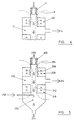
- the feed to be processed is introduced according to arrow 2.
- the feed material consists of a uranyl nitrate hexahydrate feed liquor.
- the feed liquor passes through a plasma generator (4) which rapidly heats the feed liquor to around 4000K.
- the plasma generator (4) may be a microwave or RF type plasma generator. Control of the plasma temperature can readily be provided.
- Conducting solenoids in array (6) produce a high intensity magnetic field whose lines of force are schematically represented (8).
- the stage at which the feed is ionised within the plasma generator it is already within the confines of this magnetic field.
- the conducting solenoids are set to produce a field intensity in excess of 0.1 tesla.
- the feed material enters chamber (12) at a highly elevated temperature. At this temperature the uranyl nitrate hexahydrate breaks down into its component atoms. This allows processing of the feed material according to its individual atomic make up rather than needing an elemental feed or processing the feed only according to differences between the molecules which are either subsequently ionised or not.
- the selective ionisation occurs as a result of the overall energy level of the system.
- the species which are ionised under the prevailing conditions and the species which are not, are determined by the equilibrium state for that species under those conditions.
- the selective ionisation obtained is, therefore, stable and long lasting allowing the subsequent processing to be carried out without pressure of time.
- collisions are not only tolerable they are desirable to ensure even distribution of the energy input throughout the plasma. Collisions, however, have no detrimental effect as, for example, a collision between a U+ ion and an F atom will, under the equilibrium conditions prevailing result in a U+ ion and a F atom as the most probable outcome.
- the equilibrium conditions do not provide sufficient energy for the collision to result in electron transfer and discharge of the ion.
- the potential for allowing collisions also means that the plasma can be operated in a relatively dense state allowing a significant throughput of material. If collisions have to be avoided then as low a density of ions and atoms as possible is desirable to reduce the probability of collisions.
- the uranium ions are contained by the magnetic field and encouraged to pass onward through the super conducting solenoids (6).
- the uncharged nature of the nitrogen, oxygen and hydrogen atoms allows them to move freely, unfettered by the magnetic field and they can consequently be "pumped” out of the chamber (12), stream (14). Vacuum pumps can be used for this purpose.
- the uranium has been separated from the other elements forming the uranyl nitrate hexahydrate feed. Subsequent processing of the separated uranium can be conducted as required.
- portion (16) of the process strictly confines the uranium ions.
- the temperature can be reduced still further and the uranium oxide rapidly-brought from a gaseous state into a solid state in the form of a ceramic powder, location (54). This exits as stream (58).
- the product can be subjected to further subsequent processing, for instance to upgrade it to fuel grade materials.
- the process thus provides in a single modular unit for the conversion of uranyl nitrate hexahydrate feed liquor into uranium dioxide powder.
- a similar result with other feed compounds and/or mixtures of feed compounds can be obtained.
- a single modular unit corresponding to this process having an overall length of approximately 10 m and an active region of about 1 m in diameter can process between 50 and 200 kg/hr of feed uranium.
- Residence time within the unit is very low, in the order of 10 ms. This time is a reflection of the theoretical average speed at which uranium ions travel at 4000K i.e. 6 x 10 4 cm/s.
- Spent fuel consists principally of UO 2 powder in combination with various fission products, generally of less than 60 atomic weight, low levels of 235 U and plutonium.
- the product stream (14) may be subjected to further processing, including a further process step or steps according to this invention to separate components, isotopes or elements of interest fro the other species in the stream.
- the product stream (16) may be quenched as described above to produce a solid product.
- the product may be subjected to conventional enrichment techniques. These may be used to separate adequately the 238 U, 235 U and plutonium isotopes from one another as desired and so achieve a reactor grade material.
- the feed material may be provided with an additional system to provide or ensure the required ionisation of the selected component or components.
- the feed material consists of titanium tetrachloride and the desired product is titanium metal, but the technique is equally applicable to a wide range of feed materials.
- the feed (2) passes through a plasma generator (4) and is contained in a magnetic field (8).
- the plasma temperature is such that the feed materials are reduced to discrete atoms and may be partially ionised.
- the feed then passes through an electron cyclotron resonance unit (102) which causes further energy input to the plasma due to collision of the high energy electrons with the components.
- an electron cyclotron resonance unit (102) which causes further energy input to the plasma due to collision of the high energy electrons with the components.
- certain components, titanium in this case, are ionised whereas others, chlorine, remain in un-ionised form.
- the selective ionisation is due to the equilibrium states of the species, between ionised and non-ionised, which prevail.
- the material then passes into chamber (12) where the uncharged chlorine can be removed from the magnetic field as process stream (14). the chlorine can be recycled to earlier stages in the overall process involved in the production of titanium tetrachloride.
- the present process offers a convenient way for separating the uranium metal from the uranyl nitrate hexahydrate feed.
- Uranyl nitrate hexahydrate feed (200) is introduced into the apparatus.
- the feed consists elementally of uranium, nitrogen, oxygen and hydrogen.
- the microwave or RF type plasma generator (202) very rapidly subjects the feed to a temperature of around 4000K.
- the feed is converted to U, N, N 2 , O 2 , H etc. with some U+.
- the atomised feed is contained in the plasma, the plasma being contained by the magnetic field (204) generated by magnets (206).
- an electron cyclotron resonance aerial (208) is provided to cause the desired degree of ionisation.
- the aerial (208) imparts energy to electrons present within the plasma and the increased energy of the electrons is such that on collision with the components of the feed energy is transferred. According to the equilibrium applicable to the species involved in the collision under the prevailing conditions, ionisation occurs for some components, but not for others. The likelihood of ionisation for the various parts of the feed varies in the manner discussed above. Thus uranium for instance is ionised at a lower energy level of electron excitation than oxygen, hydrogen and the like.
- the process stream reaches chamber (210) it consists of the ionised and un-ionised components.
- the un-ionised components can be pumped out of the chamber (210) into product stream (214) as they are not restrained by the magnetic field.
- the charged components principally uranium, continue on in the process stream (212) with the plasma being contained by further magnets (216).
- Introduction of a chemical material (218) into the stream (212) effects the desired reaction or phase change on the separated charged components.
- argon at a relatively low energy level, for instance 100K the charged components can be converted to un-charged components and into the product form very rapidly due to the collision between the cool stream (218) and the stream (212).
- this transition is shown as being affected by one chemical material introduction stage but a first-stage to convert the material from charged to un-charged form and a second to convert it from a gaseous to solid form is also envisaged.
- the inert nature of the gas added gives cooling without the risk of chemical combination with the uranium. Uranium metal thus results.
- the nature of the chemical material (218) and the energy level at which it is added can be used to control the form, structure, and chemical composition of the product originating in chamber (220) and in the product stream (224).
- the introduction of oxygen could be used to convert the uranium for instance into UO 2 as an alternative to the careful control of the energy level with regard to oxygen introduced or the introduction of an inert gas to reduce the uranium ions to uranium metal forms.
- a similar process route can be used to produce uranium metal starting from uranium tetrafluoride produced during the hydrofluorination stage discussed above in relation to the extraction of uranium from primary sources.
- Processing of the first product stream (214) to make use of the elemental constituents is also envisaged.
- fluorine can be recovered from the stream for subsequent reuse in the earlier stages of the material processing.
- the feed material (200) consists of uranium hexafluoride. Selective ionisation of this feed leads to charged uranium ions and uncharged fluorine atoms. The separation of these in chamber (210) leads to an uranium ion stream (212) and fluorine stream (214). The subsequent production of uranium metal as product (224) and the re-use of the fluorine either in the nuclear fuel processing cycle or in other applications is possible.
- the application of this process is particularly envisaged for treatment of the depleted stream leaving the chemical or physical enrichment process discussed above.
- the depleted stream contains uranium hexafluoride, the concentration of 235UF6 in which is low, the 235UF6 have been extracted as far as possible for further use, the vast majority of the uranium hexafluoride being 238UF6.
- this material has no significant use and is stored as uranium hexafluoride over long periods.
- Uranium hexafluoride is relatively volatile and not an ideal storage form.
- the present technique offers the possibility of taking this depleted stream, or stored amounts of this product, and processing it to obtain useful materials.
- the liberated fluorine can be returned to the processing cycle for reuse, for instance, and the new end product, uranium metal is presented in a more readily and conveniently stored form or is made available for use.
- uranium nitride By controlling the chemical species added to the uranium ions, for instance during a quench, other compounds can also be generated, for instance uranium nitride, uranium carbide and uranium oxide products can all be made.
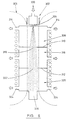
- FIG. 6 A further embodiment of the invention is illustrated schematically in Figure 6 in illustrating a further apparatus.
- the description of the device will be made in relation to separating uranium from uranium hexafluoride feed, but other applications can readily be made for this apparatus.
- the uranium hexafluoride feed liquor is introduced in stream (300) as a vapour.
- the feed is rapidly converted to a plasma by a radio frequency plasma generator (302).
- the plasma generator operates at 2KPa in order to ensure essentially equilibrium ionisation levels for the desired components of the feed due to high levels of collisions.
- Contact parts within the plasma generator may be formed from ceramic fluorides in order to give the necessary physical properties to withstand the conditions involved.
- the system may employ copper surface which is cooled by contact with water containing tubes. The water flow is used to lower the temperature of the copper walls and gives rise to condensation of the uranium fluoride forms on the walls. This chemically and thermally insulates the copper. Eventually an equilibrium state develops with a given thickness of the uranium fluoride deposited on the wall. A self-lining effect is thus provided.
- the plasma generated exits the generator (302) through nozzle (304) and is contained by magnetic field, schematically illustrated (306).
- An approximately 30mm radius nozzle is used to maintain the pressure within the plasma generator (304) and to give the desired flow rate.
- the plasma generator On leaving the plasma generator and entering zone 1 (308) the plasma will expand giving rise to cooling. However, the work done against the magnetic field by the uranium ions will result in partial re-heating. If appropriate additional energy can be introduced into the plasma during its subsequent progress through the apparatus to maintain the temperature at a level on which the desired components remain ionised. This energy may be provided by radio frequency means. The desired selectivity based on an equilibrium is thus maintained.
- the beam of material leaving the plasma generator tends to fan out as the distance from the plasma generator increases.
- the barriers (310, 312) defining the various zones take this expansion into account in their selected aperture diameters.
- the containing field is approximately 0.1 tesla in strength. Such levels can be provided by conventional electro magnetics although super conducting magnets may be employed. A magnetic field of this strength confines the uranium ions to a radius of 180mm or so following a travel distance of 3m from the nozzle. The zones / stages are each 1m in length. The radius of the expanding beam is approximately proportional to the fourth root of the distance travelled.
- outlets (314) to a vacuum pump, not shown, are provided. These allow first waste streams to be drawn off from the apparatus, the waste streams comprising non-charged material, principally fluorine. Aluminium may be used for the waste stream lines.
- the pressure in zone 1 is around 13Pa and during its travel through that zone the fluorine pressure in the material beam reduces substantially to that pressure.
- the excess fluorine over this is pumped off through outlets (314) using commercially available pumps.
- the reduced fluorine content beam then passes into zone 2 (316) through the gap (318) in barrier (310).
- the second zone (318) is operated at a lower pressure than the first, approximately 5Pa and once again the fluorine content in the beam reduces towards this pressure as the material passes through the zone.
- the beam then passes into zone 3 (320) through gap (322) in barrier (312).
- This zone is again operated at a still lower pressure, approximately 2Pa, with the excess fluorine being pumped off through outlets (324).
- the significantly depleted fluorine beam then passes on to outlet (326) for subsequent handling.
- the ionised, gaseous uranium may be contacted with a grid of some description to discharge the charge and reduce the energy of the uranium to a state in which it is solid or liquid.
- the introduction of chemical materials to effect a quenching and/or cooling action may be considered.
- the use of inert gases to cool the uranium may be preferred so that a chemical combination with the gases does not occur.
- Metallic uranium arises as a result.
- the uranium may be cooled sufficiently to provide it as a solid or alternatively may only be partially cooled to leave it in liquid form.
- the fluorine remaining in the uranium product stream (326) may be readily volatised, as a uranium fluoride, from the bulk of the uranium product and recycled.
- the separation may conveniently be carried out in situ.
- the volatised UF will largely be converted to UF 6 which can be recycled.
- Provision for collecting fluorine released from the liquid by off gassing may be provided.
- Ceramic fluoride or graphite materials may be used to form the liquid collection vessel.
Landscapes
- Physics & Mathematics (AREA)
- Engineering & Computer Science (AREA)
- Chemical & Material Sciences (AREA)
- Chemical Kinetics & Catalysis (AREA)
- Plasma & Fusion (AREA)
- General Engineering & Computer Science (AREA)
- High Energy & Nuclear Physics (AREA)
- Physical Or Chemical Processes And Apparatus (AREA)
- Inorganic Compounds Of Heavy Metals (AREA)
- Manufacture And Refinement Of Metals (AREA)
- Graft Or Block Polymers (AREA)
- Electrical Discharge Machining, Electrochemical Machining, And Combined Machining (AREA)
- Solid-Sorbent Or Filter-Aiding Compositions (AREA)
- Compounds Of Iron (AREA)
- Extraction Or Liquid Replacement (AREA)
- Treatment Of Liquids With Adsorbents In General (AREA)
- Transition And Organic Metals Composition Catalysts For Addition Polymerization (AREA)
- General Preparation And Processing Of Foods (AREA)
- Treatment Of Water By Ion Exchange (AREA)
- Lubricants (AREA)
- Separation Using Semi-Permeable Membranes (AREA)
Claims (37)
- Procédé comprenant les étapes consistant à :a) fournir une alimentation, l'alimentation étant constituée de composés mélangés ;b) convertir ladite alimentation en un plasma ou une forme ionisée ;c)foumir au moins un composant sous forme au moins partiellement ionisée, et au moins un composant différent sous une forme au moins partiellement non ionisée ;d) contenir ledit plasma/lesdits ions dans un champ magnétique ; ete) séparer lesdits composants ionisés desdits composants non ionisés, caractérisé en ce que les composants ionisés et non ionisés de l'alimentation sont en équilibre l'un par rapport à l'autre pour les conditions qui prévalent.
- Procédé selon la revendication 1, dans lequel le procédé consiste en outre à convertir au moins une partie du composant ou des composant ionisé(s) séparé(s) en une forme non ionisée.
- Procédé selon la revendication 1 ou la revendication 2, dans lequel l'ionisation des composants est provoquée par la température du plasma et/ou par l'interaction des composants avec des électrons rapides produits par résonance cyclotron des électrons.
- Procédé selon l'une quelconque des revendications 1 à 3, dans lequel l'ionisation est contrôlée par le niveau de la puissance énergétique d'entrée.
- Procédé selon l'une quelconque des revendications 1 à 4, dans lequel la puissance énergétique d'entrée n'est pas sélective entre les composants de l'alimentation.
- Procédé selon l'une quelconque des revendications 2 à 5, dans lequel l'un des composants ou les deux composants sont recueillis, les conditions de température étant contrôlées pour purifier le composant recueilli par vaporisation des impuretés.
- Procédé selon la revendication 6, dans lequel les impuretés sont vaporisées sous forme de composés avec le composant et/ou le métal recueillis.
- Procédé selon l'une quelconque des revendications 1 à 7, dans lequel la séparation des composants ionisés et non ionisés est affectée par l'élimination du composant non ionisé du plasma, alors que le composant ionisé est retenu par le champ magnétique.
- Procédé selon l'une quelconque des revendications 1 à 8, dans lequel la séparation est affectée dans plusieurs étages et dans lequel les étages fonctionnent à différentes pressions l'un par rapport à l'autre, la pression dans un ou plusieurs étages près de l'admission étant plus élevée que dans l'un ou plusieurs étages plus éloignés de l'admission.
- Procédé selon la revendication 9, dans lequel trois étages sont proposés, la première zone fonctionne entre 10 et 50 Pa, la deuxième zone fonctionne entre 5 et 20 Pa et la troisième zone fonctionne entre 2 et 10 Pa.
- Procédé selon l'une quelconque des revendications 2 à 10, dans lequel le composant est converti en une forme non chargée en réduisant son niveau d'énergie cinétique.
- Procédé selon l'une quelconque des revendications 2 à 11, dans lequel le composant est converti en une forme non ionisée en le heurtant sur une surface, de préférence une surface refroidie.
- Procédé selon l'une quelconque des revendications 2 à 11, dans lequel le composant est converti en une forme non ionisée par l'addition d'une substance chimique.
- Procédé selon la revendication 13, dans lequel la substance chimique est ajoutée à un niveau d'énergie cinétique prédéterminé afin de donner la forme non ionisée désirée sous une forme gazeuse.
- Procédé selon la revendication 13 ou la revendication 14, dans lequel l'addition de la substance chimique ou l'addition d'une autre substance chimique dans un étage plus éloigné, est telle qu'elle réduit le niveau d'énergie cinétique à un degré où un produit solide est produit.
- Procédé selon l'une quelconque des revendications 1 à 15, dans lequel le procédé comprend l'étape supplémentaire consistant à introduire une substance chimique, à un niveau d'énergie cinétique donné, et à la mettre en contact avec le(s) composant(s) restant(s), le niveau d'énergie cinétique du composant ionisé et de la substance chimique étant tels qu'une particule ou un composant non ionisé en résulte.
- Procédé selon la revendication 16, dans lequel les composants et la substance chimique supplémentaire sont combinés dans la particule résultante.
- Procédé selon l'une quelconque des revendications 1 à 17, dans lequel le composant désiré est extrait d'un mélange d'isotopes et/ou d'éléments de nature à la fois métallique et non métallique.
- Procédé selon l'une quelconque des revendications 1 à 18, dans lequel l'alimentation est fournie sous forme gazeuse par ébullition et/ou évaporation et/ou sublimation d'une alimentation initiale solide ou liquide.
- Procédé selon l'une quelconque des revendications 1 à 19, dans lequel certains ou tous les éléments métalliques présents dans ladite alimentation sont ionisés.
- Procédé selon la revendication 20, dans lequel les éléments métalliques dont le poids atomique est supérieur à 90 sont ionisés.
- Procédé selon l'une quelconque des revendications 1 à 21, dans lequel l'alimentation est fournie sous forme moléculaire et sélectivement séparée sous forme d'atomes discrets.
- Procédé selon l'une quelconque des revendications 1 à 22, dans lequel l'alimentation est introduite dans le champ magnétique contenant, sous forme non ionisée.
- Procédé selon l'une quelconque des revendications 1 à 23, dans lequel les composants non ionisés séparés sont recyclés pour une utilisation ultérieure et/ou soumis à un autre traitement.
- Procédé selon l'une quelconque des revendications 1 à 24, dans lequel les composants ionisés sont refroidis, et/ou déchargés pour fournir un produit liquide ou solide non ionisé.
- Procédé selon l'une quelconque des revendications 1 à 25, dans lequel l'alimentation comprend du combustible nucléaire irradié, du tétrafluorure d'uranium, des halogénures métalliques, du tétrachlorure de titane.
- Dispositif de séparation, ledit dispositif comprenant :a) un générateur de plasma/d'ion ;b) des moyens pour ioniser de manière sélective les composants mélangés alimentés ;c) un champ magnétique générant des moyens pour la production d'un champ magnétique pour contenir le plasma/les ions ; etd) des moyens pour éliminer les composants non chargés du champ magnétique, caractérisé en ce que les moyens des rubriques a) et b) sont tels que les composants ionisés et non ionisés de l'alimentation obtenus sont en équilibre l'un par rapport à l'autre pour les conditions qui prévalent.
- Dispositif selon la revendication 27, dans lequel des moyens pour convertir au moins certains des composants ionisés séparés en une forme non ionisée sont fournis.
- Dispositif selon la revendication 27 ou la revendication 28, dans lequel le plasma/les ions sont générés par chauffage par fréquence radio ou micro-ondes.
- Dispositif selon l'une quelconque des revendications 27 à 29, dans lequel un four, un réchauffeur, une source de micro-ondes ou un évaporateur sont utilisés pour chauffer et/ou vaporiser l'alimentation.
- Dispositif selon l'une quelconque des revendications 27 à 30, dans lequel l'ionisation partielle/la non ionisation partielle de l'alimentation résultante est à l'état d'équilibre.
- Dispositif selon l'une quelconque des revendications 27 à 31, dans lequel les moyens pour éliminer les composants non ionisés comprennent une pompe.
- Dispositif selon l'une quelconque des revendications 27 à 32, dans lequel les composants non ionisés sont séparés de l'alimentation dans un ou plusieurs étages.
- Dispositif selon la revendication 33, dans lequel les étages sont séparés l'un de l'autre par un élément cloison muni d'une ouverture.
- Dispositif selon la revendication 34, dans lequel l'ouverture a un rayon correspondant substantiellement au rayon du flux de plasma/d'ions à cette distance de l'admission, et où le rayon d'une ou plusieurs ouvertures est approximativement proportionnel à la racine quatrième de la distance par rapport à l'admission ou à la buse du générateur de plasma.
- Dispositif selon l'une quelconque des revendications 27 à 35, dans lequel le dispositif fournit en outre des moyens pour l'addition d'une substance chimique au flux du procédé restant pour fournir une action de trempe et/ou de refroidissement aux composants restants.
- Dispositif de séparation selon l'une quelconque des revendications 27 à 36, dans lequel la substance chimique est introduite dans plusieurs étages, les diverses admissions étant séparées l'une de l'autre le long de la direction du parcours du flux du procédé.
Priority Applications (1)
| Application Number | Priority Date | Filing Date | Title |
|---|---|---|---|
| EP20020018066 EP1256370A3 (fr) | 1996-03-15 | 1997-03-12 | Séparation d'isotopes par ionisation pour le traitement de matériaux combustibles nucléaires |
Applications Claiming Priority (7)
| Application Number | Priority Date | Filing Date | Title |
|---|---|---|---|
| GB9605435 | 1996-03-15 | ||
| GBGB9605435.8A GB9605435D0 (en) | 1996-03-15 | 1996-03-15 | Improvements in and relating to processing |
| GBGB9610606.7A GB9610606D0 (en) | 1996-03-15 | 1996-05-21 | Improvements in and relating to processing |
| GB9610606 | 1996-05-21 | ||
| GB9704078A GB9704078D0 (en) | 1996-03-15 | 1997-02-23 | Improvements in and relating to processing |
| GB9704078 | 1997-02-27 | ||
| PCT/GB1997/000671 WO1997034684A1 (fr) | 1996-03-15 | 1997-03-12 | Separation d'isotopes par ionisation en vue du traitement de materiaux combustibles nucleaires |
Related Child Applications (1)
| Application Number | Title | Priority Date | Filing Date |
|---|---|---|---|
| EP20020018066 Division EP1256370A3 (fr) | 1996-03-15 | 1997-03-12 | Séparation d'isotopes par ionisation pour le traitement de matériaux combustibles nucléaires |
Publications (2)
| Publication Number | Publication Date |
|---|---|
| EP0904146A1 EP0904146A1 (fr) | 1999-03-31 |
| EP0904146B1 true EP0904146B1 (fr) | 2002-08-14 |
Family
ID=27268180
Family Applications (1)
| Application Number | Title | Priority Date | Filing Date |
|---|---|---|---|
| EP97907180A Expired - Lifetime EP0904146B1 (fr) | 1996-03-15 | 1997-03-12 | Separation de composants d un melange par ionisation selective |
Country Status (19)
| Country | Link |
|---|---|
| US (1) | US6267850B1 (fr) |
| EP (1) | EP0904146B1 (fr) |
| JP (1) | JP2000506776A (fr) |
| CN (1) | CN1161178C (fr) |
| AT (1) | ATE222140T1 (fr) |
| AU (1) | AU1932697A (fr) |
| BR (1) | BR9708204A (fr) |
| CA (1) | CA2248870A1 (fr) |
| CZ (1) | CZ293398A3 (fr) |
| DE (1) | DE69714730T2 (fr) |
| ES (1) | ES2182034T3 (fr) |
| GB (1) | GB9704078D0 (fr) |
| NO (1) | NO984253L (fr) |
| NZ (1) | NZ331896A (fr) |
| PL (1) | PL328927A1 (fr) |
| RU (1) | RU2216390C2 (fr) |
| SK (1) | SK126398A3 (fr) |
| TR (1) | TR199801834T2 (fr) |
| WO (1) | WO1997034684A1 (fr) |
Families Citing this family (33)
| Publication number | Priority date | Publication date | Assignee | Title |
|---|---|---|---|---|
| WO1998037948A1 (fr) * | 1997-02-25 | 1998-09-03 | British Nuclear Fuels Plc | Procede et appareil permettant de recueillir et/ou separer des especes ionisees |
| US6203669B1 (en) | 1997-11-14 | 2001-03-20 | Archimedes Technology Group, Inc. | Nuclear waste separator |
| GB9900836D0 (en) * | 1999-01-15 | 1999-03-31 | British Nuclear Fuels Plc | Improvements in and relating to processing materials |
| RU2169607C2 (ru) * | 1999-04-27 | 2001-06-27 | Институт ядерной физики СО РАН | Антенна для разделения изотопов на второй гармонике циклотронной частоты методом ионно-циклотронного резонанса |
| RU2158169C1 (ru) * | 1999-10-26 | 2000-10-27 | Комбинат "Электрохимприбор" | Способ разделения изотопов титана в электромагнитном сепараторе с использованием источника ионов |
| US7064740B2 (en) | 2001-11-09 | 2006-06-20 | Sharp Laboratories Of America, Inc. | Backlit display with improved dynamic range |
| US7571814B2 (en) * | 2002-02-22 | 2009-08-11 | Wave Separation Technologies Llc | Method for separating metal values by exposing to microwave/millimeter wave energy |
| RU2262759C2 (ru) * | 2003-11-18 | 2005-10-20 | Объединенный Институт Ядерных Исследований | Способ получения изотопа урана-237 |
| WO2005052673A2 (fr) | 2003-11-21 | 2005-06-09 | Sharp Laboratories Of America, Inc. | Affichage a cristaux liquides a couleurs adaptatives |
| JP4757201B2 (ja) * | 2003-12-18 | 2011-08-24 | シャープ株式会社 | 液晶ディスプレイのためのダイナミックガンマ |
| US7612757B2 (en) | 2004-05-04 | 2009-11-03 | Sharp Laboratories Of America, Inc. | Liquid crystal display with modulated black point |
| US7602369B2 (en) | 2004-05-04 | 2009-10-13 | Sharp Laboratories Of America, Inc. | Liquid crystal display with colored backlight |
| US7532192B2 (en) | 2004-05-04 | 2009-05-12 | Sharp Laboratories Of America, Inc. | Liquid crystal display with filtered black point |
| US7777714B2 (en) | 2004-05-04 | 2010-08-17 | Sharp Laboratories Of America, Inc. | Liquid crystal display with adaptive width |
| US7505018B2 (en) | 2004-05-04 | 2009-03-17 | Sharp Laboratories Of America, Inc. | Liquid crystal display with reduced black level insertion |
| US7872631B2 (en) | 2004-05-04 | 2011-01-18 | Sharp Laboratories Of America, Inc. | Liquid crystal display with temporal black point |
| US8395577B2 (en) | 2004-05-04 | 2013-03-12 | Sharp Laboratories Of America, Inc. | Liquid crystal display with illumination control |
| US7023451B2 (en) | 2004-06-14 | 2006-04-04 | Sharp Laboratories Of America, Inc. | System for reducing crosstalk |
| US7556836B2 (en) | 2004-09-03 | 2009-07-07 | Solae, Llc | High protein snack product |
| US7898519B2 (en) | 2005-02-17 | 2011-03-01 | Sharp Laboratories Of America, Inc. | Method for overdriving a backlit display |
| US7525528B2 (en) | 2004-11-16 | 2009-04-28 | Sharp Laboratories Of America, Inc. | Technique that preserves specular highlights |
| US8050511B2 (en) | 2004-11-16 | 2011-11-01 | Sharp Laboratories Of America, Inc. | High dynamic range images from low dynamic range images |
| US8050512B2 (en) | 2004-11-16 | 2011-11-01 | Sharp Laboratories Of America, Inc. | High dynamic range images from low dynamic range images |
| RU2293060C2 (ru) * | 2004-12-16 | 2007-02-10 | Федеральное государственное унитарное предприятие "Государственный научный центр Российской Федерации - Научно-исследовательский институт атомных реакторов" | Способ получения мононитрида урана и смеси мононитридов урана и плутония |
| US20060233685A1 (en) * | 2005-04-15 | 2006-10-19 | Janes Clarence W | Non-aqueous method for separating chemical constituents in spent nuclear reactor fuel |
| US9143657B2 (en) | 2006-01-24 | 2015-09-22 | Sharp Laboratories Of America, Inc. | Color enhancement technique using skin color detection |
| US8121401B2 (en) | 2006-01-24 | 2012-02-21 | Sharp Labortories of America, Inc. | Method for reducing enhancement of artifacts and noise in image color enhancement |
| US9056272B2 (en) * | 2006-02-28 | 2015-06-16 | Tarek A. Z. Farag | Isotopes separation and purification in an electrolytic medium |
| US8941580B2 (en) | 2006-11-30 | 2015-01-27 | Sharp Laboratories Of America, Inc. | Liquid crystal display with area adaptive backlight |
| RU2453620C1 (ru) * | 2011-05-26 | 2012-06-20 | Федеральное государственное бюджетное учреждение Национальный исследовательский центр "Курчатовский институт" | Способ переработки гексафторида урана и устройство для его осуществления |
| WO2015026848A2 (fr) * | 2013-08-23 | 2015-02-26 | Energysolutions, Inc | Systèmes et procédés de séparation isotopique de l'eau |
| CN113118449A (zh) * | 2019-12-31 | 2021-07-16 | 有研工程技术研究院有限公司 | 一种多组分金属物质的物理分离方法和装置 |
| CN115845610A (zh) * | 2023-02-20 | 2023-03-28 | 北京核力同创科技有限公司 | 钛同位素的分离方法及系统、电子设备及存储介质 |
Citations (1)
| Publication number | Priority date | Publication date | Assignee | Title |
|---|---|---|---|---|
| JPS5811026A (ja) * | 1981-07-04 | 1983-01-21 | ジエイ・エル・ハツシユフエルド | 異なる原子量の物質を分離する方法および装置 |
Family Cites Families (10)
| Publication number | Priority date | Publication date | Assignee | Title |
|---|---|---|---|---|
| DE1943588C1 (de) * | 1969-08-27 | 1977-12-22 | Kernverfahrenstechnik Gmbh | Verfahren und Vorrichtung zur Trennung eines wenigstens teilweise ionisierten Gasgemisches in eine leichtere und eine schwerere Fraktion |
| US3992625A (en) * | 1973-12-27 | 1976-11-16 | Jersey Nuclear-Avco Isotopes, Inc. | Method and apparatus for extracting ions from a partially ionized plasma using a magnetic field gradient |
| US3973926A (en) * | 1974-01-23 | 1976-08-10 | Advanced Technology Laboratories, Inc. | Process and equipment for the magnetic separation of isotopes |
| US4093856A (en) * | 1976-06-09 | 1978-06-06 | Trw Inc. | Method of and apparatus for the electrostatic excitation of ions |
| FR2363364A1 (fr) * | 1976-09-07 | 1978-03-31 | Thomson Csf | Procede de separation isotopique et installation pour sa mise en oeuvre |
| US4213043A (en) * | 1977-07-20 | 1980-07-15 | Trw Inc. | Method for flowing a large volume of plasma through an excitation region |
| US4208582A (en) * | 1977-12-05 | 1980-06-17 | Trw Inc. | Isotope separation apparatus |
| US4786478A (en) * | 1984-07-26 | 1988-11-22 | Conoco Inc. | Method and apparatus for isotope separation |
| SU1533058A1 (ru) * | 1987-09-14 | 1992-02-15 | A Ya Voronov | Cпocoб paздeлehия изotoпob элektpootpицateльhoгo гaзa |
| FR2705584B1 (fr) * | 1993-05-26 | 1995-06-30 | Commissariat Energie Atomique | Dispositif de séparation isotopique par résonance cyclotronique ionique. |
-
1997
- 1997-02-23 GB GB9704078A patent/GB9704078D0/en active Pending
- 1997-03-12 DE DE69714730T patent/DE69714730T2/de not_active Expired - Fee Related
- 1997-03-12 BR BR9708204A patent/BR9708204A/pt not_active Application Discontinuation
- 1997-03-12 EP EP97907180A patent/EP0904146B1/fr not_active Expired - Lifetime
- 1997-03-12 RU RU98118698A patent/RU2216390C2/ru not_active IP Right Cessation
- 1997-03-12 PL PL32892797A patent/PL328927A1/xx unknown
- 1997-03-12 CN CNB971943702A patent/CN1161178C/zh not_active Expired - Fee Related
- 1997-03-12 CA CA 2248870 patent/CA2248870A1/fr not_active Abandoned
- 1997-03-12 AU AU19326/97A patent/AU1932697A/en not_active Abandoned
- 1997-03-12 TR TR1998/01834T patent/TR199801834T2/xx unknown
- 1997-03-12 WO PCT/GB1997/000671 patent/WO1997034684A1/fr not_active Ceased
- 1997-03-12 AT AT97907180T patent/ATE222140T1/de not_active IP Right Cessation
- 1997-03-12 SK SK1263-98A patent/SK126398A3/sk unknown
- 1997-03-12 US US09/142,781 patent/US6267850B1/en not_active Expired - Fee Related
- 1997-03-12 NZ NZ33189697A patent/NZ331896A/xx unknown
- 1997-03-12 CZ CZ982933A patent/CZ293398A3/cs unknown
- 1997-03-12 JP JP53322397A patent/JP2000506776A/ja not_active Ceased
- 1997-03-12 ES ES97907180T patent/ES2182034T3/es not_active Expired - Lifetime
-
1998
- 1998-09-14 NO NO984253A patent/NO984253L/no not_active Application Discontinuation
Patent Citations (1)
| Publication number | Priority date | Publication date | Assignee | Title |
|---|---|---|---|---|
| JPS5811026A (ja) * | 1981-07-04 | 1983-01-21 | ジエイ・エル・ハツシユフエルド | 異なる原子量の物質を分離する方法および装置 |
Also Published As
| Publication number | Publication date |
|---|---|
| CN1217671A (zh) | 1999-05-26 |
| GB9704078D0 (en) | 1997-04-16 |
| TR199801834T2 (xx) | 1998-12-21 |
| US6267850B1 (en) | 2001-07-31 |
| RU2216390C2 (ru) | 2003-11-20 |
| CA2248870A1 (fr) | 1997-09-25 |
| SK126398A3 (en) | 1999-04-13 |
| CN1161178C (zh) | 2004-08-11 |
| EP0904146A1 (fr) | 1999-03-31 |
| NO984253L (no) | 1998-11-16 |
| DE69714730D1 (de) | 2002-09-19 |
| CZ293398A3 (cs) | 1999-05-12 |
| ES2182034T3 (es) | 2003-03-01 |
| NO984253D0 (no) | 1998-09-14 |
| DE69714730T2 (de) | 2003-04-24 |
| BR9708204A (pt) | 1999-07-27 |
| NZ331896A (en) | 2000-05-26 |
| ATE222140T1 (de) | 2002-08-15 |
| WO1997034684A1 (fr) | 1997-09-25 |
| JP2000506776A (ja) | 2000-06-06 |
| PL328927A1 (en) | 1999-03-01 |
| AU1932697A (en) | 1997-10-10 |
Similar Documents
| Publication | Publication Date | Title |
|---|---|---|
| EP0904146B1 (fr) | Separation de composants d un melange par ionisation selective | |
| US6323455B1 (en) | Separation of isotopes by ionisation for processing of nuclear fuel materials | |
| EP1144701B1 (fr) | Retraitement de matieres uraniferes par fluorination et separation des hexafluorures d'uranium obtenus dans un reacteur a plasma | |
| EP1256370A2 (fr) | Séparation d'isotopes par ionisation pour le traitement de matériaux combustibles nucléaires | |
| AU742347B2 (en) | Separation of isotopes by ionisation for processing of nuclear fuel materials | |
| Yuferov et al. | Calculations of ion trajectories at magnetoplasma separation and experiments with polyatomic gases | |
| MXPA98007540A (en) | Separation of isotopes by ionization for processing of nucl fuel materials | |
| Yuferov et al. | Some questions of snf reprocessing at the stages of ionization and magnetoplasma separation in crossed fields | |
| EP0963238B1 (fr) | Procede et appareil permettant de recueillir et/ou separer des especes ionisees | |
| US2879130A (en) | Process for recovering uranium | |
| KR20000064623A (ko) | 핵연료재료를처리하기위한이온화에의한동위원소의분리방법과장치 |
Legal Events
| Date | Code | Title | Description |
|---|---|---|---|
| PUAI | Public reference made under article 153(3) epc to a published international application that has entered the european phase |
Free format text: ORIGINAL CODE: 0009012 |
|
| 17P | Request for examination filed |
Effective date: 19980930 |
|
| AK | Designated contracting states |
Kind code of ref document: A1 Designated state(s): AT DE DK ES FI FR GB IT NL PT SE |
|
| AX | Request for extension of the european patent |
Free format text: LT PAYMENT 980930;LV PAYMENT 980930;RO PAYMENT 980930 |
|
| 17Q | First examination report despatched |
Effective date: 19991105 |
|
| GRAG | Despatch of communication of intention to grant |
Free format text: ORIGINAL CODE: EPIDOS AGRA |
|
| GRAG | Despatch of communication of intention to grant |
Free format text: ORIGINAL CODE: EPIDOS AGRA |
|
| GRAG | Despatch of communication of intention to grant |
Free format text: ORIGINAL CODE: EPIDOS AGRA |
|
| GRAH | Despatch of communication of intention to grant a patent |
Free format text: ORIGINAL CODE: EPIDOS IGRA |
|
| RTI1 | Title (correction) |
Free format text: SEPARATION OF COMPONENTS IN A MIXED FEED BY SELECTIVE IONISATION |
|
| GRAH | Despatch of communication of intention to grant a patent |
Free format text: ORIGINAL CODE: EPIDOS IGRA |
|
| GRAA | (expected) grant |
Free format text: ORIGINAL CODE: 0009210 |
|
| AK | Designated contracting states |
Kind code of ref document: B1 Designated state(s): AT DE DK ES FI FR GB IT NL PT SE |
|
| AX | Request for extension of the european patent |
Free format text: LT PAYMENT 19980930;LV PAYMENT 19980930;RO PAYMENT 19980930 |
|
| PG25 | Lapsed in a contracting state [announced via postgrant information from national office to epo] |
Ref country code: NL Free format text: LAPSE BECAUSE OF FAILURE TO SUBMIT A TRANSLATION OF THE DESCRIPTION OR TO PAY THE FEE WITHIN THE PRESCRIBED TIME-LIMIT Effective date: 20020814 Ref country code: FI Free format text: LAPSE BECAUSE OF FAILURE TO SUBMIT A TRANSLATION OF THE DESCRIPTION OR TO PAY THE FEE WITHIN THE PRESCRIBED TIME-LIMIT Effective date: 20020814 Ref country code: AT Free format text: LAPSE BECAUSE OF FAILURE TO SUBMIT A TRANSLATION OF THE DESCRIPTION OR TO PAY THE FEE WITHIN THE PRESCRIBED TIME-LIMIT Effective date: 20020814 |
|
| REF | Corresponds to: |
Ref document number: 222140 Country of ref document: AT Date of ref document: 20020815 Kind code of ref document: T |
|
| REG | Reference to a national code |
Ref country code: GB Ref legal event code: FG4D |
|
| REF | Corresponds to: |
Ref document number: 69714730 Country of ref document: DE Date of ref document: 20020919 |
|
| PG25 | Lapsed in a contracting state [announced via postgrant information from national office to epo] |
Ref country code: DK Free format text: LAPSE BECAUSE OF FAILURE TO SUBMIT A TRANSLATION OF THE DESCRIPTION OR TO PAY THE FEE WITHIN THE PRESCRIBED TIME-LIMIT Effective date: 20021114 |
|
| PG25 | Lapsed in a contracting state [announced via postgrant information from national office to epo] |
Ref country code: PT Free format text: LAPSE BECAUSE OF FAILURE TO SUBMIT A TRANSLATION OF THE DESCRIPTION OR TO PAY THE FEE WITHIN THE PRESCRIBED TIME-LIMIT Effective date: 20021129 |
|
| LTIE | Lt: invalidation of european patent or patent extension |
Effective date: 20020814 |
|
| NLV1 | Nl: lapsed or annulled due to failure to fulfill the requirements of art. 29p and 29m of the patents act | ||
| PGFP | Annual fee paid to national office [announced via postgrant information from national office to epo] |
Ref country code: SE Payment date: 20030214 Year of fee payment: 7 |
|
| REG | Reference to a national code |
Ref country code: ES Ref legal event code: FG2A Ref document number: 2182034 Country of ref document: ES Kind code of ref document: T3 |
|
| ET | Fr: translation filed | ||
| PGFP | Annual fee paid to national office [announced via postgrant information from national office to epo] |
Ref country code: ES Payment date: 20030311 Year of fee payment: 7 |
|
| PLBE | No opposition filed within time limit |
Free format text: ORIGINAL CODE: 0009261 |
|
| STAA | Information on the status of an ep patent application or granted ep patent |
Free format text: STATUS: NO OPPOSITION FILED WITHIN TIME LIMIT |
|
| 26N | No opposition filed |
Effective date: 20030515 |
|
| PG25 | Lapsed in a contracting state [announced via postgrant information from national office to epo] |
Ref country code: SE Free format text: LAPSE BECAUSE OF NON-PAYMENT OF DUE FEES Effective date: 20040313 Ref country code: ES Free format text: LAPSE BECAUSE OF NON-PAYMENT OF DUE FEES Effective date: 20040313 |
|
| EUG | Se: european patent has lapsed | ||
| PGFP | Annual fee paid to national office [announced via postgrant information from national office to epo] |
Ref country code: FR Payment date: 20050211 Year of fee payment: 9 |
|
| PGFP | Annual fee paid to national office [announced via postgrant information from national office to epo] |
Ref country code: GB Payment date: 20050214 Year of fee payment: 9 |
|
| PGFP | Annual fee paid to national office [announced via postgrant information from national office to epo] |
Ref country code: DE Payment date: 20050216 Year of fee payment: 9 |
|
| PG25 | Lapsed in a contracting state [announced via postgrant information from national office to epo] |
Ref country code: IT Free format text: LAPSE BECAUSE OF NON-PAYMENT OF DUE FEES Effective date: 20050312 |
|
| REG | Reference to a national code |
Ref country code: ES Ref legal event code: FD2A Effective date: 20040313 |
|
| PG25 | Lapsed in a contracting state [announced via postgrant information from national office to epo] |
Ref country code: GB Free format text: LAPSE BECAUSE OF NON-PAYMENT OF DUE FEES Effective date: 20060312 |
|
| PG25 | Lapsed in a contracting state [announced via postgrant information from national office to epo] |
Ref country code: DE Free format text: LAPSE BECAUSE OF NON-PAYMENT OF DUE FEES Effective date: 20061003 |
|
| GBPC | Gb: european patent ceased through non-payment of renewal fee |
Effective date: 20060312 |
|
| REG | Reference to a national code |
Ref country code: FR Ref legal event code: ST Effective date: 20061130 |
|
| PG25 | Lapsed in a contracting state [announced via postgrant information from national office to epo] |
Ref country code: FR Free format text: LAPSE BECAUSE OF NON-PAYMENT OF DUE FEES Effective date: 20060331 |