EP0904158B1 - Vorrichtung zum herstellen eines dreidimensionalen körpers - Google Patents
Vorrichtung zum herstellen eines dreidimensionalen körpers Download PDFInfo
- Publication number
- EP0904158B1 EP0904158B1 EP96910384A EP96910384A EP0904158B1 EP 0904158 B1 EP0904158 B1 EP 0904158B1 EP 96910384 A EP96910384 A EP 96910384A EP 96910384 A EP96910384 A EP 96910384A EP 0904158 B1 EP0904158 B1 EP 0904158B1
- Authority
- EP
- European Patent Office
- Prior art keywords
- drops
- reactant
- liquid
- cross
- prepared
- Prior art date
- Legal status (The legal status is an assumption and is not a legal conclusion. Google has not performed a legal analysis and makes no representation as to the accuracy of the status listed.)
- Expired - Lifetime
Links
- 238000000034 method Methods 0.000 title claims abstract description 64
- 230000015572 biosynthetic process Effects 0.000 title description 6
- 239000007788 liquid Substances 0.000 claims abstract description 113
- 239000000203 mixture Substances 0.000 claims abstract description 113
- 239000000376 reactant Substances 0.000 claims abstract description 82
- 239000007787 solid Substances 0.000 claims abstract description 31
- 238000002360 preparation method Methods 0.000 claims abstract description 14
- 239000000243 solution Substances 0.000 claims description 29
- 238000006243 chemical reaction Methods 0.000 claims description 28
- 239000000126 substance Substances 0.000 claims description 23
- 238000005516 engineering process Methods 0.000 claims description 22
- 239000002245 particle Substances 0.000 claims description 18
- 102000008186 Collagen Human genes 0.000 claims description 16
- 108010035532 Collagen Proteins 0.000 claims description 16
- 229920001436 collagen Polymers 0.000 claims description 16
- XLYOFNOQVPJJNP-UHFFFAOYSA-N water Substances O XLYOFNOQVPJJNP-UHFFFAOYSA-N 0.000 claims description 16
- 238000000151 deposition Methods 0.000 claims description 14
- BNIILDVGGAEEIG-UHFFFAOYSA-L disodium hydrogen phosphate Chemical compound [Na+].[Na+].OP([O-])([O-])=O BNIILDVGGAEEIG-UHFFFAOYSA-L 0.000 claims description 14
- 229910000397 disodium phosphate Inorganic materials 0.000 claims description 14
- 239000012530 fluid Substances 0.000 claims description 13
- UXVMQQNJUSDDNG-UHFFFAOYSA-L Calcium chloride Chemical compound [Cl-].[Cl-].[Ca+2] UXVMQQNJUSDDNG-UHFFFAOYSA-L 0.000 claims description 12
- 239000001110 calcium chloride Substances 0.000 claims description 11
- 229910001628 calcium chloride Inorganic materials 0.000 claims description 11
- 230000008569 process Effects 0.000 claims description 10
- 239000007864 aqueous solution Substances 0.000 claims description 9
- 238000013461 design Methods 0.000 claims description 9
- 238000011282 treatment Methods 0.000 claims description 7
- 239000003054 catalyst Substances 0.000 claims description 4
- 229910003480 inorganic solid Inorganic materials 0.000 claims description 4
- 239000004020 conductor Substances 0.000 claims description 3
- 150000002500 ions Chemical class 0.000 claims 4
- 238000009825 accumulation Methods 0.000 claims 2
- SQDAZGGFXASXDW-UHFFFAOYSA-N 5-bromo-2-(trifluoromethoxy)pyridine Chemical compound FC(F)(F)OC1=CC=C(Br)C=N1 SQDAZGGFXASXDW-UHFFFAOYSA-N 0.000 claims 1
- 229920001287 Chondroitin sulfate Polymers 0.000 claims 1
- 229940059329 chondroitin sulfate Drugs 0.000 claims 1
- 239000010410 layer Substances 0.000 description 91
- 239000000725 suspension Substances 0.000 description 31
- 238000004519 manufacturing process Methods 0.000 description 25
- 238000011960 computer-aided design Methods 0.000 description 22
- 239000000463 material Substances 0.000 description 22
- 239000013078 crystal Substances 0.000 description 17
- QORWJWZARLRLPR-UHFFFAOYSA-H tricalcium bis(phosphate) Chemical compound [Ca+2].[Ca+2].[Ca+2].[O-]P([O-])([O-])=O.[O-]P([O-])([O-])=O QORWJWZARLRLPR-UHFFFAOYSA-H 0.000 description 16
- 229910052588 hydroxylapatite Inorganic materials 0.000 description 15
- XYJRXVWERLGGKC-UHFFFAOYSA-D pentacalcium;hydroxide;triphosphate Chemical compound [OH-].[Ca+2].[Ca+2].[Ca+2].[Ca+2].[Ca+2].[O-]P([O-])([O-])=O.[O-]P([O-])([O-])=O.[O-]P([O-])([O-])=O XYJRXVWERLGGKC-UHFFFAOYSA-D 0.000 description 15
- 239000001506 calcium phosphate Substances 0.000 description 14
- 235000011010 calcium phosphates Nutrition 0.000 description 14
- 239000002244 precipitate Substances 0.000 description 14
- 229920000642 polymer Polymers 0.000 description 13
- 239000011230 binding agent Substances 0.000 description 12
- IISBACLAFKSPIT-UHFFFAOYSA-N bisphenol A Chemical compound C=1C=C(O)C=CC=1C(C)(C)C1=CC=C(O)C=C1 IISBACLAFKSPIT-UHFFFAOYSA-N 0.000 description 12
- 229910000389 calcium phosphate Inorganic materials 0.000 description 11
- 238000002156 mixing Methods 0.000 description 10
- NBIIXXVUZAFLBC-UHFFFAOYSA-K phosphate Chemical compound [O-]P([O-])([O-])=O NBIIXXVUZAFLBC-UHFFFAOYSA-K 0.000 description 9
- 239000010419 fine particle Substances 0.000 description 8
- VYPSYNLAJGMNEJ-UHFFFAOYSA-N Silicium dioxide Chemical compound O=[Si]=O VYPSYNLAJGMNEJ-UHFFFAOYSA-N 0.000 description 7
- PNEYBMLMFCGWSK-UHFFFAOYSA-N aluminium oxide Inorganic materials [O-2].[O-2].[O-2].[Al+3].[Al+3] PNEYBMLMFCGWSK-UHFFFAOYSA-N 0.000 description 7
- 239000000919 ceramic Substances 0.000 description 7
- 238000010438 heat treatment Methods 0.000 description 7
- 229920001228 polyisocyanate Polymers 0.000 description 7
- 239000005056 polyisocyanate Substances 0.000 description 7
- BRLQWZUYTZBJKN-UHFFFAOYSA-N Epichlorohydrin Chemical compound ClCC1CO1 BRLQWZUYTZBJKN-UHFFFAOYSA-N 0.000 description 6
- YXFVVABEGXRONW-UHFFFAOYSA-N Toluene Chemical compound CC1=CC=CC=C1 YXFVVABEGXRONW-UHFFFAOYSA-N 0.000 description 6
- 239000000470 constituent Substances 0.000 description 6
- 238000005755 formation reaction Methods 0.000 description 6
- 230000004048 modification Effects 0.000 description 6
- 238000012986 modification Methods 0.000 description 6
- 230000036961 partial effect Effects 0.000 description 6
- 229910019142 PO4 Inorganic materials 0.000 description 5
- 239000007795 chemical reaction product Substances 0.000 description 5
- 239000003795 chemical substances by application Substances 0.000 description 5
- 239000010452 phosphate Substances 0.000 description 5
- 235000021317 phosphate Nutrition 0.000 description 5
- 229920005862 polyol Polymers 0.000 description 5
- 150000003077 polyols Chemical class 0.000 description 5
- 239000004814 polyurethane Substances 0.000 description 5
- 229920002635 polyurethane Polymers 0.000 description 5
- -1 CaO Chemical compound 0.000 description 4
- VTYYLEPIZMXCLO-UHFFFAOYSA-L Calcium carbonate Chemical compound [Ca+2].[O-]C([O-])=O VTYYLEPIZMXCLO-UHFFFAOYSA-L 0.000 description 4
- 239000004593 Epoxy Substances 0.000 description 4
- NBIIXXVUZAFLBC-UHFFFAOYSA-N Phosphoric acid Chemical compound OP(O)(O)=O NBIIXXVUZAFLBC-UHFFFAOYSA-N 0.000 description 4
- 239000003822 epoxy resin Substances 0.000 description 4
- 239000000945 filler Substances 0.000 description 4
- 229920000647 polyepoxide Polymers 0.000 description 4
- 239000000843 powder Substances 0.000 description 4
- 239000002002 slurry Substances 0.000 description 4
- 239000002904 solvent Substances 0.000 description 4
- BHPQYMZQTOCNFJ-UHFFFAOYSA-N Calcium cation Chemical compound [Ca+2] BHPQYMZQTOCNFJ-UHFFFAOYSA-N 0.000 description 3
- HEMHJVSKTPXQMS-UHFFFAOYSA-M Sodium hydroxide Chemical compound [OH-].[Na+] HEMHJVSKTPXQMS-UHFFFAOYSA-M 0.000 description 3
- 230000002378 acidificating effect Effects 0.000 description 3
- 239000000853 adhesive Substances 0.000 description 3
- 230000001070 adhesive effect Effects 0.000 description 3
- 239000011324 bead Substances 0.000 description 3
- 239000011575 calcium Substances 0.000 description 3
- 229910001424 calcium ion Inorganic materials 0.000 description 3
- 230000008021 deposition Effects 0.000 description 3
- 238000001035 drying Methods 0.000 description 3
- 239000003623 enhancer Substances 0.000 description 3
- 230000006870 function Effects 0.000 description 3
- 239000007943 implant Substances 0.000 description 3
- 230000010354 integration Effects 0.000 description 3
- 239000007791 liquid phase Substances 0.000 description 3
- 229940085991 phosphate ion Drugs 0.000 description 3
- 229920003023 plastic Polymers 0.000 description 3
- 239000004033 plastic Substances 0.000 description 3
- 230000002829 reductive effect Effects 0.000 description 3
- 239000000377 silicon dioxide Substances 0.000 description 3
- 238000005245 sintering Methods 0.000 description 3
- 238000003756 stirring Methods 0.000 description 3
- 239000006228 supernatant Substances 0.000 description 3
- RYGMFSIKBFXOCR-UHFFFAOYSA-N Copper Chemical compound [Cu] RYGMFSIKBFXOCR-UHFFFAOYSA-N 0.000 description 2
- LFQSCWFLJHTTHZ-UHFFFAOYSA-N Ethanol Chemical compound CCO LFQSCWFLJHTTHZ-UHFFFAOYSA-N 0.000 description 2
- FAPWRFPIFSIZLT-UHFFFAOYSA-M Sodium chloride Chemical compound [Na+].[Cl-] FAPWRFPIFSIZLT-UHFFFAOYSA-M 0.000 description 2
- 230000009471 action Effects 0.000 description 2
- 239000000654 additive Substances 0.000 description 2
- 238000007605 air drying Methods 0.000 description 2
- 150000001298 alcohols Chemical class 0.000 description 2
- WNROFYMDJYEPJX-UHFFFAOYSA-K aluminium hydroxide Chemical compound [OH-].[OH-].[OH-].[Al+3] WNROFYMDJYEPJX-UHFFFAOYSA-K 0.000 description 2
- 229910000019 calcium carbonate Inorganic materials 0.000 description 2
- AXCZMVOFGPJBDE-UHFFFAOYSA-L calcium dihydroxide Chemical compound [OH-].[OH-].[Ca+2] AXCZMVOFGPJBDE-UHFFFAOYSA-L 0.000 description 2
- FUFJGUQYACFECW-UHFFFAOYSA-L calcium hydrogenphosphate Chemical compound [Ca+2].OP([O-])([O-])=O FUFJGUQYACFECW-UHFFFAOYSA-L 0.000 description 2
- 238000005266 casting Methods 0.000 description 2
- 239000004359 castor oil Substances 0.000 description 2
- 235000019438 castor oil Nutrition 0.000 description 2
- 230000003197 catalytic effect Effects 0.000 description 2
- 238000002425 crystallisation Methods 0.000 description 2
- 230000008025 crystallization Effects 0.000 description 2
- 230000001419 dependent effect Effects 0.000 description 2
- RBLGLDWTCZMLRW-UHFFFAOYSA-K dicalcium;phosphate;dihydrate Chemical compound O.O.[Ca+2].[Ca+2].[O-]P([O-])([O-])=O RBLGLDWTCZMLRW-UHFFFAOYSA-K 0.000 description 2
- ZPWVASYFFYYZEW-UHFFFAOYSA-L dipotassium hydrogen phosphate Chemical compound [K+].[K+].OP([O-])([O-])=O ZPWVASYFFYYZEW-UHFFFAOYSA-L 0.000 description 2
- 239000012153 distilled water Substances 0.000 description 2
- 150000002148 esters Chemical class 0.000 description 2
- 238000011156 evaluation Methods 0.000 description 2
- 238000001704 evaporation Methods 0.000 description 2
- 230000008020 evaporation Effects 0.000 description 2
- 238000011049 filling Methods 0.000 description 2
- 238000010304 firing Methods 0.000 description 2
- ZEMPKEQAKRGZGQ-XOQCFJPHSA-N glycerol triricinoleate Natural products CCCCCC[C@@H](O)CC=CCCCCCCCC(=O)OC[C@@H](COC(=O)CCCCCCCC=CC[C@@H](O)CCCCCC)OC(=O)CCCCCCCC=CC[C@H](O)CCCCCC ZEMPKEQAKRGZGQ-XOQCFJPHSA-N 0.000 description 2
- 238000011065 in-situ storage Methods 0.000 description 2
- 229910010272 inorganic material Inorganic materials 0.000 description 2
- 239000011147 inorganic material Substances 0.000 description 2
- 239000012212 insulator Substances 0.000 description 2
- 150000002576 ketones Chemical class 0.000 description 2
- 230000007246 mechanism Effects 0.000 description 2
- 229910052751 metal Inorganic materials 0.000 description 2
- 239000002184 metal Substances 0.000 description 2
- 230000003287 optical effect Effects 0.000 description 2
- 239000011236 particulate material Substances 0.000 description 2
- 239000000049 pigment Substances 0.000 description 2
- 239000002952 polymeric resin Substances 0.000 description 2
- 239000002243 precursor Substances 0.000 description 2
- 239000000047 product Substances 0.000 description 2
- 229920005989 resin Polymers 0.000 description 2
- 239000011347 resin Substances 0.000 description 2
- 229920006395 saturated elastomer Polymers 0.000 description 2
- 230000007480 spreading Effects 0.000 description 2
- 238000003892 spreading Methods 0.000 description 2
- 239000000758 substrate Substances 0.000 description 2
- 229920003002 synthetic resin Polymers 0.000 description 2
- 238000012360 testing method Methods 0.000 description 2
- GBNXLQPMFAUCOI-UHFFFAOYSA-H tetracalcium;oxygen(2-);diphosphate Chemical compound [O-2].[Ca+2].[Ca+2].[Ca+2].[Ca+2].[O-]P([O-])([O-])=O.[O-]P([O-])([O-])=O GBNXLQPMFAUCOI-UHFFFAOYSA-H 0.000 description 2
- 235000019731 tricalcium phosphate Nutrition 0.000 description 2
- 229910000391 tricalcium phosphate Inorganic materials 0.000 description 2
- 238000012800 visualization Methods 0.000 description 2
- 238000005406 washing Methods 0.000 description 2
- 238000010146 3D printing Methods 0.000 description 1
- NLHHRLWOUZZQLW-UHFFFAOYSA-N Acrylonitrile Chemical compound C=CC#N NLHHRLWOUZZQLW-UHFFFAOYSA-N 0.000 description 1
- VHUUQVKOLVNVRT-UHFFFAOYSA-N Ammonium hydroxide Chemical compound [NH4+].[OH-] VHUUQVKOLVNVRT-UHFFFAOYSA-N 0.000 description 1
- 239000004342 Benzoyl peroxide Substances 0.000 description 1
- OMPJBNCRMGITSC-UHFFFAOYSA-N Benzoylperoxide Chemical compound C=1C=CC=CC=1C(=O)OOC(=O)C1=CC=CC=C1 OMPJBNCRMGITSC-UHFFFAOYSA-N 0.000 description 1
- 229910014772 Ca8H2(PO4)6 Inorganic materials 0.000 description 1
- OYPRJOBELJOOCE-UHFFFAOYSA-N Calcium Chemical compound [Ca] OYPRJOBELJOOCE-UHFFFAOYSA-N 0.000 description 1
- ODINCKMPIJJUCX-UHFFFAOYSA-N Calcium oxide Chemical compound [Ca]=O ODINCKMPIJJUCX-UHFFFAOYSA-N 0.000 description 1
- BVKZGUZCCUSVTD-UHFFFAOYSA-L Carbonate Chemical compound [O-]C([O-])=O BVKZGUZCCUSVTD-UHFFFAOYSA-L 0.000 description 1
- 235000014653 Carica parviflora Nutrition 0.000 description 1
- 241000243321 Cnidaria Species 0.000 description 1
- 102000012422 Collagen Type I Human genes 0.000 description 1
- 108010022452 Collagen Type I Proteins 0.000 description 1
- JOYRKODLDBILNP-UHFFFAOYSA-N Ethyl urethane Chemical compound CCOC(N)=O JOYRKODLDBILNP-UHFFFAOYSA-N 0.000 description 1
- 108010010803 Gelatin Proteins 0.000 description 1
- VEXZGXHMUGYJMC-UHFFFAOYSA-N Hydrochloric acid Chemical compound Cl VEXZGXHMUGYJMC-UHFFFAOYSA-N 0.000 description 1
- DGAQECJNVWCQMB-PUAWFVPOSA-M Ilexoside XXIX Chemical compound C[C@@H]1CC[C@@]2(CC[C@@]3(C(=CC[C@H]4[C@]3(CC[C@@H]5[C@@]4(CC[C@@H](C5(C)C)OS(=O)(=O)[O-])C)C)[C@@H]2[C@]1(C)O)C)C(=O)O[C@H]6[C@@H]([C@H]([C@@H]([C@H](O6)CO)O)O)O.[Na+] DGAQECJNVWCQMB-PUAWFVPOSA-M 0.000 description 1
- 239000007836 KH2PO4 Substances 0.000 description 1
- FYYHWMGAXLPEAU-UHFFFAOYSA-N Magnesium Chemical compound [Mg] FYYHWMGAXLPEAU-UHFFFAOYSA-N 0.000 description 1
- 241001465754 Metazoa Species 0.000 description 1
- CERQOIWHTDAKMF-UHFFFAOYSA-N Methacrylic acid Chemical compound CC(=C)C(O)=O CERQOIWHTDAKMF-UHFFFAOYSA-N 0.000 description 1
- CTQNGGLPUBDAKN-UHFFFAOYSA-N O-Xylene Chemical compound CC1=CC=CC=C1C CTQNGGLPUBDAKN-UHFFFAOYSA-N 0.000 description 1
- 108010058846 Ovalbumin Proteins 0.000 description 1
- 239000004721 Polyphenylene oxide Substances 0.000 description 1
- ZLMJMSJWJFRBEC-UHFFFAOYSA-N Potassium Chemical compound [K] ZLMJMSJWJFRBEC-UHFFFAOYSA-N 0.000 description 1
- 101000941926 Saccharomyces cerevisiae (strain ATCC 204508 / S288c) Carboxypeptidase Y inhibitor Proteins 0.000 description 1
- ZJCCRDAZUWHFQH-UHFFFAOYSA-N Trimethylolpropane Chemical compound CCC(CO)(CO)CO ZJCCRDAZUWHFQH-UHFFFAOYSA-N 0.000 description 1
- BZHJMEDXRYGGRV-UHFFFAOYSA-N Vinyl chloride Chemical compound ClC=C BZHJMEDXRYGGRV-UHFFFAOYSA-N 0.000 description 1
- 239000002253 acid Substances 0.000 description 1
- 150000007513 acids Chemical class 0.000 description 1
- 230000004913 activation Effects 0.000 description 1
- 230000000996 additive effect Effects 0.000 description 1
- 150000001338 aliphatic hydrocarbons Chemical class 0.000 description 1
- AZDRQVAHHNSJOQ-UHFFFAOYSA-N alumane Chemical class [AlH3] AZDRQVAHHNSJOQ-UHFFFAOYSA-N 0.000 description 1
- 229910052782 aluminium Inorganic materials 0.000 description 1
- XAGFODPZIPBFFR-UHFFFAOYSA-N aluminium Chemical compound [Al] XAGFODPZIPBFFR-UHFFFAOYSA-N 0.000 description 1
- 229910000147 aluminium phosphate Inorganic materials 0.000 description 1
- 239000000908 ammonium hydroxide Substances 0.000 description 1
- 239000002518 antifoaming agent Substances 0.000 description 1
- 150000004945 aromatic hydrocarbons Chemical class 0.000 description 1
- 239000003849 aromatic solvent Substances 0.000 description 1
- 229910002113 barium titanate Inorganic materials 0.000 description 1
- JRPBQTZRNDNNOP-UHFFFAOYSA-N barium titanate Chemical compound [Ba+2].[Ba+2].[O-][Ti]([O-])([O-])[O-] JRPBQTZRNDNNOP-UHFFFAOYSA-N 0.000 description 1
- 238000005452 bending Methods 0.000 description 1
- 230000008901 benefit Effects 0.000 description 1
- 235000019400 benzoyl peroxide Nutrition 0.000 description 1
- OHJMTUPIZMNBFR-UHFFFAOYSA-N biuret Chemical compound NC(=O)NC(N)=O OHJMTUPIZMNBFR-UHFFFAOYSA-N 0.000 description 1
- 230000037237 body shape Effects 0.000 description 1
- 210000000988 bone and bone Anatomy 0.000 description 1
- 229910052791 calcium Inorganic materials 0.000 description 1
- XAAHAAMILDNBPS-UHFFFAOYSA-L calcium hydrogenphosphate dihydrate Chemical compound O.O.[Ca+2].OP([O-])([O-])=O XAAHAAMILDNBPS-UHFFFAOYSA-L 0.000 description 1
- 239000000920 calcium hydroxide Substances 0.000 description 1
- 229910001861 calcium hydroxide Inorganic materials 0.000 description 1
- 244000309466 calf Species 0.000 description 1
- 239000003990 capacitor Substances 0.000 description 1
- 229910010293 ceramic material Inorganic materials 0.000 description 1
- 230000008859 change Effects 0.000 description 1
- 239000008119 colloidal silica Substances 0.000 description 1
- 239000003086 colorant Substances 0.000 description 1
- 238000001816 cooling Methods 0.000 description 1
- 229910052802 copper Inorganic materials 0.000 description 1
- 239000010949 copper Substances 0.000 description 1
- PMHQVHHXPFUNSP-UHFFFAOYSA-M copper(1+);methylsulfanylmethane;bromide Chemical compound Br[Cu].CSC PMHQVHHXPFUNSP-UHFFFAOYSA-M 0.000 description 1
- 208000002925 dental caries Diseases 0.000 description 1
- 239000003479 dental cement Substances 0.000 description 1
- 210000003298 dental enamel Anatomy 0.000 description 1
- 230000001687 destabilization Effects 0.000 description 1
- 238000011161 development Methods 0.000 description 1
- GYZLOYUZLJXAJU-UHFFFAOYSA-N diglycidyl ether Chemical compound C1OC1COCC1CO1 GYZLOYUZLJXAJU-UHFFFAOYSA-N 0.000 description 1
- 229910000396 dipotassium phosphate Inorganic materials 0.000 description 1
- 239000002270 dispersing agent Substances 0.000 description 1
- 238000000203 droplet dispensing Methods 0.000 description 1
- 239000003759 ester based solvent Substances 0.000 description 1
- RTZKZFJDLAIYFH-UHFFFAOYSA-N ether Substances CCOCC RTZKZFJDLAIYFH-UHFFFAOYSA-N 0.000 description 1
- 238000002474 experimental method Methods 0.000 description 1
- 230000004438 eyesight Effects 0.000 description 1
- 230000002349 favourable effect Effects 0.000 description 1
- 238000010100 freeform fabrication Methods 0.000 description 1
- 229920000159 gelatin Polymers 0.000 description 1
- 239000008273 gelatin Substances 0.000 description 1
- 235000019322 gelatine Nutrition 0.000 description 1
- 235000011852 gelatine desserts Nutrition 0.000 description 1
- 239000011521 glass Substances 0.000 description 1
- 230000005484 gravity Effects 0.000 description 1
- LNEPOXFFQSENCJ-UHFFFAOYSA-N haloperidol Chemical compound C1CC(O)(C=2C=CC(Cl)=CC=2)CCN1CCCC(=O)C1=CC=C(F)C=C1 LNEPOXFFQSENCJ-UHFFFAOYSA-N 0.000 description 1
- XLYOFNOQVPJJNP-ZSJDYOACSA-N heavy water Substances [2H]O[2H] XLYOFNOQVPJJNP-ZSJDYOACSA-N 0.000 description 1
- 125000004836 hexamethylene group Chemical group [H]C([H])([*:2])C([H])([H])C([H])([H])C([H])([H])C([H])([H])C([H])([H])[*:1] 0.000 description 1
- 229910000041 hydrogen chloride Inorganic materials 0.000 description 1
- IXCSERBJSXMMFS-UHFFFAOYSA-N hydrogen chloride Substances Cl.Cl IXCSERBJSXMMFS-UHFFFAOYSA-N 0.000 description 1
- 230000006872 improvement Effects 0.000 description 1
- 238000010348 incorporation Methods 0.000 description 1
- 239000003112 inhibitor Substances 0.000 description 1
- 239000003999 initiator Substances 0.000 description 1
- 230000000977 initiatory effect Effects 0.000 description 1
- 238000007641 inkjet printing Methods 0.000 description 1
- 229910052809 inorganic oxide Inorganic materials 0.000 description 1
- 239000010954 inorganic particle Substances 0.000 description 1
- 230000002452 interceptive effect Effects 0.000 description 1
- 238000005495 investment casting Methods 0.000 description 1
- 239000012948 isocyanate Substances 0.000 description 1
- 150000002513 isocyanates Chemical class 0.000 description 1
- 238000005304 joining Methods 0.000 description 1
- 230000003902 lesion Effects 0.000 description 1
- 230000000670 limiting effect Effects 0.000 description 1
- 239000006194 liquid suspension Substances 0.000 description 1
- 230000004807 localization Effects 0.000 description 1
- 229920002521 macromolecule Polymers 0.000 description 1
- 229910052749 magnesium Inorganic materials 0.000 description 1
- 239000011777 magnesium Substances 0.000 description 1
- 239000011159 matrix material Substances 0.000 description 1
- 238000011089 mechanical engineering Methods 0.000 description 1
- 230000008018 melting Effects 0.000 description 1
- 238000002844 melting Methods 0.000 description 1
- 150000002739 metals Chemical class 0.000 description 1
- 239000003607 modifier Substances 0.000 description 1
- 239000000178 monomer Substances 0.000 description 1
- 229910000402 monopotassium phosphate Inorganic materials 0.000 description 1
- CVPJXKJISAFJDU-UHFFFAOYSA-A nonacalcium;magnesium;hydrogen phosphate;iron(2+);hexaphosphate Chemical compound [Mg+2].[Ca+2].[Ca+2].[Ca+2].[Ca+2].[Ca+2].[Ca+2].[Ca+2].[Ca+2].[Ca+2].[Fe+2].OP([O-])([O-])=O.OP([O-])([O-])=O.[O-]P([O-])([O-])=O.[O-]P([O-])([O-])=O.[O-]P([O-])([O-])=O.[O-]P([O-])([O-])=O.[O-]P([O-])([O-])=O.[O-]P([O-])([O-])=O CVPJXKJISAFJDU-UHFFFAOYSA-A 0.000 description 1
- 239000000615 nonconductor Substances 0.000 description 1
- 229910000392 octacalcium phosphate Inorganic materials 0.000 description 1
- 238000011022 operating instruction Methods 0.000 description 1
- 125000000466 oxiranyl group Chemical group 0.000 description 1
- 230000037361 pathway Effects 0.000 description 1
- 239000003209 petroleum derivative Substances 0.000 description 1
- 229920002239 polyacrylonitrile Polymers 0.000 description 1
- 229920005906 polyester polyol Polymers 0.000 description 1
- 229920000570 polyether Polymers 0.000 description 1
- 229920001223 polyethylene glycol Polymers 0.000 description 1
- 239000004848 polyfunctional curative Substances 0.000 description 1
- 238000006116 polymerization reaction Methods 0.000 description 1
- 229920000193 polymethacrylate Polymers 0.000 description 1
- 239000011527 polyurethane coating Substances 0.000 description 1
- 229920002451 polyvinyl alcohol Polymers 0.000 description 1
- 235000019422 polyvinyl alcohol Nutrition 0.000 description 1
- 239000011591 potassium Substances 0.000 description 1
- 229910052700 potassium Inorganic materials 0.000 description 1
- GNSKLFRGEWLPPA-UHFFFAOYSA-M potassium dihydrogen phosphate Chemical compound [K+].OP(O)([O-])=O GNSKLFRGEWLPPA-UHFFFAOYSA-M 0.000 description 1
- 238000001556 precipitation Methods 0.000 description 1
- 238000007639 printing Methods 0.000 description 1
- 238000012545 processing Methods 0.000 description 1
- 230000005855 radiation Effects 0.000 description 1
- 230000007420 reactivation Effects 0.000 description 1
- 239000012744 reinforcing agent Substances 0.000 description 1
- 230000003252 repetitive effect Effects 0.000 description 1
- 230000000284 resting effect Effects 0.000 description 1
- 238000012552 review Methods 0.000 description 1
- 239000000523 sample Substances 0.000 description 1
- 239000002356 single layer Substances 0.000 description 1
- 230000036555 skin type Effects 0.000 description 1
- 239000011734 sodium Substances 0.000 description 1
- 229910052708 sodium Inorganic materials 0.000 description 1
- 239000011780 sodium chloride Substances 0.000 description 1
- AJPJDKMHJJGVTQ-UHFFFAOYSA-M sodium dihydrogen phosphate Chemical compound [Na+].OP(O)([O-])=O AJPJDKMHJJGVTQ-UHFFFAOYSA-M 0.000 description 1
- 159000000000 sodium salts Chemical class 0.000 description 1
- 239000007790 solid phase Substances 0.000 description 1
- 238000007711 solidification Methods 0.000 description 1
- 230000008023 solidification Effects 0.000 description 1
- 238000000935 solvent evaporation Methods 0.000 description 1
- 241000894007 species Species 0.000 description 1
- 230000002269 spontaneous effect Effects 0.000 description 1
- 239000007921 spray Substances 0.000 description 1
- 238000000967 suction filtration Methods 0.000 description 1
- 238000001356 surgical procedure Methods 0.000 description 1
- 229920001059 synthetic polymer Polymers 0.000 description 1
- YIGWVOWKHUSYER-UHFFFAOYSA-F tetracalcium;hydrogen phosphate;diphosphate Chemical compound [Ca+2].[Ca+2].[Ca+2].[Ca+2].OP([O-])([O-])=O.[O-]P([O-])([O-])=O.[O-]P([O-])([O-])=O YIGWVOWKHUSYER-UHFFFAOYSA-F 0.000 description 1
- 239000002470 thermal conductor Substances 0.000 description 1
- 229920002803 thermoplastic polyurethane Polymers 0.000 description 1
- 210000001519 tissue Anatomy 0.000 description 1
- 230000008016 vaporization Effects 0.000 description 1
- 238000009423 ventilation Methods 0.000 description 1
- 239000000080 wetting agent Substances 0.000 description 1
- 229910052591 whitlockite Inorganic materials 0.000 description 1
- 239000008096 xylene Substances 0.000 description 1
Images

Classifications
-
- B—PERFORMING OPERATIONS; TRANSPORTING
- B29—WORKING OF PLASTICS; WORKING OF SUBSTANCES IN A PLASTIC STATE IN GENERAL
- B29C—SHAPING OR JOINING OF PLASTICS; SHAPING OF MATERIAL IN A PLASTIC STATE, NOT OTHERWISE PROVIDED FOR; AFTER-TREATMENT OF THE SHAPED PRODUCTS, e.g. REPAIRING
- B29C41/00—Shaping by coating a mould, core or other substrate, i.e. by depositing material and stripping-off the shaped article; Apparatus therefor
- B29C41/34—Component parts, details or accessories; Auxiliary operations
- B29C41/36—Feeding the material on to the mould, core or other substrate
-
- B—PERFORMING OPERATIONS; TRANSPORTING
- B29—WORKING OF PLASTICS; WORKING OF SUBSTANCES IN A PLASTIC STATE IN GENERAL
- B29C—SHAPING OR JOINING OF PLASTICS; SHAPING OF MATERIAL IN A PLASTIC STATE, NOT OTHERWISE PROVIDED FOR; AFTER-TREATMENT OF THE SHAPED PRODUCTS, e.g. REPAIRING
- B29C64/00—Additive manufacturing, i.e. manufacturing of three-dimensional [3D] objects by additive deposition, additive agglomeration or additive layering, e.g. by 3D printing, stereolithography or selective laser sintering
- B29C64/10—Processes of additive manufacturing
- B29C64/106—Processes of additive manufacturing using only liquids or viscous materials, e.g. depositing a continuous bead of viscous material
- B29C64/112—Processes of additive manufacturing using only liquids or viscous materials, e.g. depositing a continuous bead of viscous material using individual droplets, e.g. from jetting heads
-
- B—PERFORMING OPERATIONS; TRANSPORTING
- B29—WORKING OF PLASTICS; WORKING OF SUBSTANCES IN A PLASTIC STATE IN GENERAL
- B29K—INDEXING SCHEME ASSOCIATED WITH SUBCLASSES B29B, B29C OR B29D, RELATING TO MOULDING MATERIALS OR TO MATERIALS FOR MOULDS, REINFORCEMENTS, FILLERS OR PREFORMED PARTS, e.g. INSERTS
- B29K2105/00—Condition, form or state of moulded material or of the material to be shaped
- B29K2105/0002—Condition, form or state of moulded material or of the material to be shaped monomers or prepolymers
-
- B—PERFORMING OPERATIONS; TRANSPORTING
- B29—WORKING OF PLASTICS; WORKING OF SUBSTANCES IN A PLASTIC STATE IN GENERAL
- B29K—INDEXING SCHEME ASSOCIATED WITH SUBCLASSES B29B, B29C OR B29D, RELATING TO MOULDING MATERIALS OR TO MATERIALS FOR MOULDS, REINFORCEMENTS, FILLERS OR PREFORMED PARTS, e.g. INSERTS
- B29K2105/00—Condition, form or state of moulded material or of the material to be shaped
- B29K2105/0058—Liquid or visquous
- B29K2105/0073—Solution
Definitions
- This invention relates to a method for a free-form preparation of a free-standing three-dimensional structural body, in accordance with the first part of claim 1.
- FFM Free Form Manufacturing
- a self-supporting, or free-standing, three-dimensional unitary structural body Free Form Manufacturing or FFM. More particularly, it concerns preparing a substantially inorganic body by a "rapid prototyping" or like system which includes localized reaction of reactants in deposited discrete liquid drops deposited from liquid compositions as patterned drop configurations for providing successive cross-sectional planar-like layers of the structural body to build up cross-sectional layer-by-layer, one upon another, and thus create the free-standing, three-dimensional structural body.
- Illustrative of one such rapid prototyping method is that of fabricating three-dimensional objects by stereolithography, such as described in US-A-4,575,330, C. W. Hull. That patent teaches a generating of three-dimensional objects by creating a cross-sectional pattern of the object to be formed at a selected planar surface of a fluid medium capable of having its physical state altered. by impinging radiation or the like, for changing of the pattern on the fluid surface to a solid planar-like cross-section and then successively forming corresponding successive adjacent cross-sections of the object on top thereof with successively-created adjacent cross-sections integrated together into a laminar-like build-up of the desired object.
- Another system would use ink jet printing technology to bind a layer of ceramic particles together by selective application of a binding medium to the inorganic particles and by repetition build up cross-sectional layers into the formed body or structure.
- CAD computer aided design
- CAM computer aided manufacturing
- the sought structural body may be designed through CAD by a computer operator using computer-aided graphics and functions of the computer to design and/or sculpture a desired three-dimensional model or prototype body or the like whose image memory can be displayed on a computer screen (CRT) for subsequent review and modification, if desired.
- CRT computer screen
- the computer through CAM can create mathematical sections or slices of the designed three-dimensional model of the object into successive adjacent cross-sectional layers, and by CAM instruct a making by a specific technology of the object represented by the image.
- CAM will cut the image of the CAD-designed body or prototype into multiple successive cross-sectional layers and issue the operating instructions and parameters for successively forming by stereolithography the successively adjacent cross-sectional layers one on top of another with the layers integrated into a laminar built-up structure of the desired body of polymerized resin.
- the various fabricated bodies are useful in a variety of applications.
- a natural application is the creation of a concept model so that a designed part can be touched and examined and reviewed for aesthetic purposes and possibly tested for its fit, its ergomatic feasibility and the like utility requisites.
- the economics of fabrication may be even more favorable than using more elaborate tooling for fabrication. Models and prototypes thus can be evaluated and their parameters and dimensions altered and finalized for further evaluation and testing of the altered bodies.
- Some other illustrative utilities for various generated bodies from various materials include: calcium phosphate and hydroxylapatite materials to generate customized bodies for orthopaedic hard tissue implants; solid-liquid porous filters of various particulate materials bound together by sintering after a burn-off removal of an initial fugitive adhesive binder; heat and electrical solid insulators; as well as ceramic cores and shells for metals casting and for other purposes from alumina with colloidal silica binders or of predominantly silica or refractory inorganic oxides; and the like.
- US-A-5 257 657 discloses a method for producing a free-form solid-phase object from a material in the liquid phase which is reflected by the first part/pre-amble of claim 1.
- the object is produced from droplets of liquid-phase material having appreciable surface tension and well-defined solidification properties.
- the liquid-phase material is ejected from an ejection head in discrete droplets onto a substrate.
- an ejector head is moved relative to the surface of substrate and ejecting consecutive droplets at controllable time intervals toward a growing end of bead.
- the droplets meld with the growing end of bead while previously expelled droplets solidify toward the seed point or an originating end.
- the method of the invention comprises in general a preparing of a free-standing three-dimensional structural body, which in finished state consists essentially of inorganic material by successively generating by a successive drop placement technology of adjacent cross-sectional planar-like layers of the body with a successively freshly generated layer on top of an adjacent earlier generated cross-sectional layer and with earlier and later generated layers integrated as a whole to comprise the prepared free-standing, three-dimensional structural body.
- the invention includes depositing of earlier and later generated cross-sectional layers successively by applying to a support surface of a plurality of individual liquid drops of liquid compositions containing one or more reactant species.
- the applying of the drops is as discrete individual drops arranged in a pattern corresponding to a planar-like cross-sectional layer of the body being prepared and then followed with an applying onto and joining and/or overlapping the earlier applied plurality of individual liquid drops of the first composition with a plurality of liquid discrete drops of an other liquid composition containing an other reactant, which other reactant is such upon contacting the reactant in the liquid drops of the earlier applied composition that the reactant and other reactant react to form an inorganic material.
- the applied drops of the liquid composition and another liquid composition in addition to reactant also contain inorganic substance dissolved and/or dispersed or suspended as solid particles therein, and optionally may contain other materials (not necessarily inorganic), such as a viscosity enhancer, a resinous binder substance, or like material to facilitate practice of the method of the invention and formation of the structural body.
- the liquid compositions providing the applied drops may contain dissolved, dispersed or suspended particles of the same or different composition of the solid(s) resulting from reaction of the reactants in the applied drops.
- the support surface onto which are deposited an initial pattern of drops as well as a later pattern of drops to generate the initial cross-sectional layer of the body desirably is adapted to facilitate liquid removal from applied drops, such as by being porous to absorb by capillarity or to wick away liquid from the deposited drops.
- CAD computer aided design
- CAM computer aided manufacturing
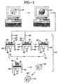
- FIG. 1 presents, in an essentially schematic-type format, various successive steps for the rapid-prototype method technique utilizing CAD and CAM technologies to manufacture a free-standing, three-dimensional structural body and with greater schematic detail given for the instant invention's successive-drop-technique generation and integration of adjacent cross-sectional, planar-like layers into a desired free-standing, three-dimensional structural body.
- FIG. 2 illustrates, in perspective view, a sectional portion of a being-prepared partial free-standing, three-dimensional body sectioned at a location of an earlier prepared integrated cross-sectional layer of the body and with this earlier prepared layer being a support surface upon which is illustrated a partial formation of the next adjacent cross-sectional layer being generated.
- FIG. 3 illustrates a planar partial view of a top corner, taken on coordinate axis lines X and Y, of the top portion of the being-prepared layer portion of the free-standing, three-dimensional structural body shown in FIG. 3.
- FIG. 1 10 represents an initial step of origination of and/or a design or structural model or body (10), capable of being visualized on a CRT screen, of a free-standing three-dimensional structural body desired to be generated.
- the design may be from an original concept (e.g. created) by computer-aided design techniques using computer aided graphic programs and the like and created, when desired, to provide and to conform to designated parameters, including shape, size and dimensions, for CRT display.
- an earlier e.g. manually sculptured or fabricated model or body
- an earlier e.g. manually sculptured or fabricated model or body
- FIG. 1 one such structural body, designated 10, for example is shown schematically as a pentagonal-sided short bar having an about centrally located cylindrical hole running longitudinally therethrough, displayed on a schematically represented computer CRT screen.
- FIG. 1 11 schematically designate a following step and/or sliced result (11) of this following step, wherein the computer's memory bank stored file of the design or structural model or body desired to be generated now has been sliced into a plurality of cross-sectional (planar-like or relatively two-dimensional) slices for subsequent utilization in the next step, 12, of essence to applicant's invention.
- cross-sectional slices and their thickness is dependent on parameters and materials employed in the next-to-follow step.
- cross-sectional layer thicknesses ranging from 0.0005 to 0.0015 inch (0.0127 mm to 0.0384 mm) to have utility.
- Obtaining this degree of resolution with the invention will involve optimizing device design such that materials, particle sizes, drop sizes, drop nozzle sizes, will permit the resolution to be accomplished.
- This degree of resolution is expected to be readily obtainable without undue experimentation by one of ordinary skill in the FFM art in view of this application's teachings of the invention.
- subsequently placed smaller' drops and more drops placed per unit area generally provides smaller layer thicknesses along with improvement in resolution and control of dimensions of the being-formed body and are to be expected to be very desirable and useful.
- FIG. 1 the next illustrated step involves an overall generation and integration step (12) of the computer file of sequential cross-sectional adjacent layer slices into a desired structural body (32').
- FIG. 1 in a more detailed schematic presents the multiple layer slice generation and integration step (12) including the invention's unique successive drop placements of liquid drops 27, containing a first reactant, in a pattern followed by placement of contacting drops 30 containing another reactant in an overlying contacting pattern.
- a movable support base 20 such as an elevator platform adjustable to be moved to an up or down location by means of a ram 21 and by a mechanical, hydraulic or like movement means, not shown.
- the support base 20 moves within guide slides 22 to better control the support's movement alignment and placement.
- FIG. 1 the support base 20 and ram 21 and slides 22 are shown for upward and downward movement, depending upon the particular drop application means being employed and its location as well as the specific or particular configuration of the body to be generated, the location placement of 20, 21 and 22 can be at various vertical angles, even as far as sideways (horizontal) and even to provide for upward movement and upwardly or angularly deposited drop applications depending on particularly employed drop application means and the specific compositions of the first and another liquid drops.
- porous support base 23 Resting upon movable support base 20 is a, generally attached thereto, porous support base 23, upon which, by the invention's successive drop applications, there is created an initial planar-like cross-sectional layer of the three-dimensional body to be generated.
- the support base 23 is illustrated as porous so that it better may wick away (e.g. by capillary action) liquid from subsequently applied drops 27 and 30.
- faucet-water aspirator means such as useful in suction filtration, or mechanical pumps for reduced pressure generating means, also not illustrated, could by one of ordinary skill be installed, attached, and adapted so that the porosity in support base 23 is at a reduced pressure and thus adapted to expedite liquid removal from applied drops 27 and 30.
- other and additional means to expedite liquid removal may be incorporated.
- heating means such as sealed electrical resistance elements, not illustrated, within porous support base 23 and/or support base 20, could be utilized so as to vaporize liquid from applied drops, and when so employed desirably would be accompanied by installed duct work (not illustrated) and by forced withdrawal fan ventilation means or the like (not illustrated) adapted to withdraw liquid vapors from the vicinity of drop's applications upon the placed or deposited drops being heated. Such heat also could expedite reaction of the reactants.
- Other means and techniques for facilitating liquid removal from applied drops will be apparent to the art and also are considered within the scope and intent of the invention.
- the partially generated body 25 in its far left presentation is at a midway point of generation or fabrication so that illustrated is the partially formed body at a process of preparation of an about vertically half-way-located cross-sectional, horizontal layer upon an earlier prepared underlying horizontal cross-sectional layer by depositing and/or placing in a designated pattern of the being formed cross-sectional layer of a plurality of drops 27 of a fluid composition by a not illustrated dispensing or depositing means through a deposit outlet means, such as a nozzle 26.
- the patterned drop 30 application is so aligned with the earlier placed patterned drop 27 application that the two applications contact in a manner adapted for reactants in the drops to contact, generally overlap, to react with the formed reaction product to become a solid which integrates with an earlier prepared underlying layer.
- the reaction between the reactants in the applied first drop composition and the applied second or another drop composition continues to proceed to a movably-complete state of a cross-sectional layer from which significant and substantial liquid content of the applied drops has flowed and/or by other means been removed, although the just prepared cross-sectional layer may still be liquid-moist and or pasty-like in consistency.
- step 12 for preparation of a next on top cross-sectional layer, the movement (shown by directional arrows) of partial body 25 and its ancillary accompanying elements is to the initial far left position wherein a patterned depositing of drops 27 again would be made and followed by movement therefrom to the central position wherein a patterned depositing of drops 30 again would be made before moving to the far right position. Thereafter this sequence is repeated, such as for (n) times, where n represents the total of the successively prepared cross-sectional layers making up the generated body, now designated 32.
- the body 32 at this completion stage of step 12 preparation can be deemed to have green strength, depending on the extent of liquid removal therefrom, the extent of progression of the reaction of the reactants with each other, the nature of the components of the compositions including therein the amount, type, size and like of dispersed material, including binders, viscosity-enhancers and the like, with adequate green strength invariably reached relatively quickly to a strength value permitting removal of body 32 from porous support 23 and upon drying further with or without a heating means (not illustrated) to become substantially reaction-complete, or dry enough, now to be designated body 32'.
- FIG. 1 for step 12 illustrates movements of the being generated body 32 and 32' to various locations, such as left-to-right horizontal movement and upward and downward vertical movement to various locations for procedural drop application of one composition, followed by drop application of another application, and to a location, if needed, for drying and/or reaction completion before movement for repetition of this sequence, all such movement is relative and is to be so understood. Thus movement also may be right to left. Also porous support 23 and its ancillary positioning elements and the being prepared partial body 25 may be held in a stationary position and instead movement may be made of deposit outlet means 27 and 29 to provide requisite positioning for applications of drops 27 and 30 and a drying/reaction period before repeating the cycle and generating a successive cross-sectional layer upon an earlier generated layer.
- the illustrated schematic position location can be at various angles from horizontal and vertical such as even may be needed for a specific particular structural configuration of the to-be-generated structural body.
- body 32' optionally may be processed further from step 12 through any of numerous procedures to be discussed later in a step designated 13 in FIG. 1, to provide an optionally processed generated body 32" having properties even more desirable or requisite and compatible for its end utility application.
- Example I For proceeding through step 12 of FIG. 1 in place of the micropipettes employed in a soon to be described Example I, it is contemplated that there be employed apparatus of the nature of and/or closely akin to ink-jet printers used in computer technology with little to no modification thereof of commercially available ink-jet printers being needed for practicing step 12.
- An ink jet printer functions by supplying a drop-on-demand of an ink composition to a printing surface.
- One type called a "bubble jet”
- an electrical current passes through the resistance and ink in the tube is heated.
- a portion near the heater vaporizes and expands, pushing a drop of ink from the nozzle of the tiny tube.
- the vaporizing in the tube creates a bubble and upon the bubble contracting, after the ink drop is expelled and released, there is created a drop in pressure that pulls more ink into the tube.
- a reactivation of the resistance heater permits a new drop to be ejected.
- an apparatus element arrangement of a plurality of tiny tubes and their directed nozzles and with the resistance heaters operated as dictated and controlled by the computer, one can rapidly deposit to print characters in numerous fonts, graphics, and the like with dot resolutions from a few drops per inch (e.g. 6-10 drops per inch wide by 6-10 drops per inch high) to higher resolutions, such as 360 by 360 dots per inch (dpi) height and width per font character printed.
- Another useful type of an ink jet printer employs for activation a piezoelectrical means to displace and eject a drop of ink from the nozzle of the tiny tube.
- compositions for the respectively applied and pattern distributed liquid drops a liquid composition containing a calcium ion for one liquid drop and a liquid composition containing a phosphate ion for the another liquid drop with the ionic components of the two liquid compositions adapted upon contact to react to form a desired calcium phosphate prosthetic material.
- Illustrative substances for supplying the calcium ion include calcium chloride (CaCl 2 ), calcium hydroxide (Ca(OH) 2 ), and lime (CaO), and for supplying the phosphate ion include sodium monobasic phosphate (NaH 2 PO 4 ) sodium dibasic phosphate (Na 2 HPO 4 ), phosphoric acid (H 3 PO 4 ), potassium monobasic phosphate (KH 2 PO 4 ), and potassium dibasic phosphate (K 2 HPO 4 ), etc., with water employed for the liquid.
- CaCl 2 calcium chloride
- Ca(OH) 2 ) calcium hydroxide
- CaO lime
- phosphate ion include sodium monobasic phosphate (NaH 2 PO 4 ) sodium dibasic phosphate (Na 2 HPO 4 ), phosphoric acid (H 3 PO 4 ), potassium monobasic phosphate (KH 2 PO 4 ), and potassium dibasic phosphate (K 2 HPO 4 ), etc.,
- the water may be made mildly acidic, such as by inclusion in the water of minor amounts of phosphoric, hydrochloric or other acids or even some basic substances compatible with reaction of the particular ionic reaction between the particular calcium and phosphate ions contained in the liquid compositions.
- a structural body for such utilities desirably contains a significant bio-compatible content of Ca 5 (PO 3 )OH(hydroxyapatite).
- Methods for providing a content of hydroxyapatite in the generated body include a supersaturating of the reactant-containing fluid compositions providing the first and second drops with dissolved hydroxyapatite, and/or suspending fine particles of hydroxyapatite therein, and/or alternatively an employing of reactants which upon reacting will form directly hydroxyapatite or form a precursor phosphate composition, capable upon a subsequent processing to form hydroxyapatite, such as by the conversion technology practical in the production of replamine form from calcium carbonate coral, when the invention's generated body contains significant precursor content of calcium carbonate.
- reactants which upon reacting will form directly hydroxyapatite or form a precursor phosphate composition, capable upon a subsequent processing to form hydroxyapatite, such as by the conversion technology practical in the production of replamine form from calcium carbonate coral, when the invention's generated body contains significant precursor content of calcium carbonate.
- one liquid composition for providing of drops containing Ca 4 (PO) 4 ) 6 •5H 2 O(tetracalcium phosphate) for its reactant and the other liquid composition for providing drops containing for its other reactant any of various other calcium phosphates namely CaHPO 4 •2H 2 O (dicalcium phosphate dihydrate or brushite), CaHPO 4 (monetite), Ca 8 H 2 (PO 4 ) 6 •5H 2 O(octacalcium phosphate), ⁇ -Ca 3 (PO 4 ) 2 , ⁇ -Ca 3 (PO 4 ) 2 (tricalcium phosphates), or tricalcium phosphates modified by the addition of protons or up to approximately 10% magnesium by weight (whitlockite), or combinations of these calcium phosphates in the other liquid composition,
- a chemical reaction of the foregoing nature is taught in US-
- the patent's composition includes all phosphate reactants in single slurry or paste composition for useful applications as remineralizers of caries lesions in dental enamel and as dental cements and the like applications.
- the tetracalcium phosphate reactant and the other reactant(s) are distributed one in one drop's liquid composition and the other in the other drop's liquid composition with the respective various drop placements of a size and applied under conditions adapted for reactant reaction, such as with a force adapted to mix already applied drops with the another applied contacting drops for the reaction between the phosphate reactants to proceed within a reasonable time to provide hydroxyapatite.
- step 12 of drop-by-drop technique for generation of successive cross-sectional layers which eventually build-up together and are integrated into a green strength structural body 32' one in some instances, when desired and/or desirable, optionally may proceed with a post-treatment 13 process step (FIG 1) of green strength structural body 32' to provide a body 32" having one or more advantageous properties over body 32'.
- a heating and/or post-firing treatment in an oven or furnace is useful.
- Firing treatments such as gradually raising the temperature of the green body 32' over a period of time up to a temperature between 1000° to 1200°C and then maintaining this higher temperature for from 1/2 to 2 hours will provide a body 32' of enhanced strength by a sintering and binding together of integrated particulates comprising body 32".
- a heat-activatable water-soluble polymeric adhesive binder is included in a liquid composition for drops 27 and/or 30 and then is present in body 32', a heating of body 32' to a requisite temperature and for a requisite time to activate the heat-activated adhesive binder is desirable as a post treatment.
- a customary practice of the invention places a pattern of drops of a first liquid composition and then places, contacting those drops, drops of another liquid composition so that one or more reactants in the drops react to form a solid to comprise the cross-sectional layer of the body being formed, there may be placed even additional drops of additional liquid compositions so as to provide solids formed by any number of reactants in the two, three, four, or more liquid compositions placed as contacting drops.
- various applied drops may contain more than a single reactant.
- various drops may contain various individual reactants adapted to react to provide inorganic solid, and the same or other applied drops may contain additional other reactants adapted to provide another solid (e.g.
- a resinous binder substance which serves in part as a solid component comprising the cross-sectional layer of the body being prepared.
- applied drops in addition to reactants, may contain other substances, as described herein, such as catalysts, inhibitors, fillers, binders, etc.
- a 0.75M CaCl 2 solution was prepared at room temperature by magnetic-stir-mixing 41.6g of desiccant-grade CaCl 2 into 500 ml of distilled H 2 O until dissolved (approximately 20 minutes).
- a 0.5M Na 2 HPO 4 solution was prepared by mixing 35.4g of reagent-grade Na 2 HPO 4 into 500 ml of H 2 O until dissolved (approximately 40 minutes).
- Additional 0.5M reagent-grade Na 2 HPO 4 aqueous solution was prepared as described earlier.
- a 0.86M desiccant-grade calcium chloride aqueous solution was prepared by the earlier described general procedure for preparation of the 0.75M CaCl 2 aqueous solution.
- Prior to use the collagen solution was dialized with dilute HCL solution at a pH of 2-3. The dialized solution provided 3 mg. collagen per ml. of dialized solution.
- a like depositing of successive drops of the first and second suspensions was made with the order of placing drops down being reversed so that drops of the phosphate ion suspension were laid down first and then subsequently connected by laying down drops of the calcium ion suspension.
- the order of placements of the two suspension's drops appeared to make no difference in the resulting ridged solid-like structures which formed, except that a collagen film was wider around drops laid down first than around the drops laid down second.
- the ridge formations at drop interfaces appeared to be a primary site for calcium phosphate formation and precipitation to occur upon the drops of the first and second differing suspension compositions contacting and interacting upon the inter-drop contact-mixing occurring.
- the collagen content of the drops apparently serves to confine most of the formed precipitated crystals to be located at or near drops' interfaces and to be denser in nature than crystals formed in the drop's interior region by crystallization as the water from the various drops gradually dissipated (e.g. by room-temperature evaporation).
- the experimental procedure of the I(A) experimental trial was repeated with 10 ⁇ l drops of the first solution deposited in a plastic petri dish and with spacing between deposited individual drops being close enough that subsequently deposited drops of the prepared second solution would connect the first deposited adjacent drops by contacting sides of the first deposited drops and/or slightly overlapping the individual first deposited drops.
- lines of crystalline precipitate formed at interfaces of adjacent drops upon the secondly deposited drops contacting or overlapping the firstly deposited drops.
- Observations at 70X showed a formed crystalline fibrous matrix interlaced with fine precipitated crystals.
- Three-dimensional FFM structures or bodies were prepared as follows:
- a truncated 4-sided hollow pyramid, several inches (750 mm) in height and about 1.5 in ( ⁇ 35-40mm) base per side dimension also was made.
- the air-dried created bodies can be kiln-fired to 1100° C to 1300°C for 1 to 5 hours to provide a fused and/or sintered stronger bodies.
- Heat-fused and/or sintered created bodies are useful electrical conduit insulators in flat, columnar, tubular, ring, and the like shapes.
- Hydroxyapatite crystals are prepared as taught by T. Aaba and E. C. Moreno in J. Dent. Res., June, 1984, pp. 874-880, and utilized in place of the Example I prepared aqueous fine particle calcium phosphate precipitate of undetermined purity and composition.
- the prepared hydroxyapatite crystals, while still moist, and as replacement for the calcium phosphate precipitate of Example I, are dispersed as seed for crystallization in each of the first suspension and the second suspension with the first and second suspensions each containing amounts of the seed to supersaturate so as to provide metastable supersaturated fluid compositions.
- discrete drops of the first suspension are applied in a line pattern to a porous support and followed by applying discrete drops of the second suspension overlapping adjacently placed drops of the first suspension and with this sequence of drop placements repeated successively for requisite times to build a three-dimensional structural green body of a vertical wall about 0.25 in (6.4 mm) wide to a height of 1 in (25.4 mm) which wall comprises a significant amount of hydroxyapatite seed crystals surrounded by calcium phosphate precipitate formed by reaction of the calcium chloride in the first suspension's drops with the Na 2 HPO 4 content of the second suspension's drops.
- the thus fabricated wall-like and somewhat porous body also contains collagen and is contemplated to be useful in restorative surgery as a non-load bearing bone implant in animals.
- the generated green body is fired at 1100° to 1200°C for about 1 hour.
- the initial step 10 is practiced to create and/or visualize a model of the object or body to be generated or created with CAD technology and techniques employed for the creation and visualization.
- the CAD generated model then by CAM computer technology and programming is subjected to the step 11 of creation of a computer file of cross-sectional adjacent sliced layers of the CAD-generated model.
- the essential procedural sequence step, designated 12 is performed of physically generating and integrating the CAD generated and filed of adjacent sliced layers of the model into the laminar-like fabricated or created structural body.
- CAM technology is employed to specify, control and regulate various procedural parameters, such as drop size, drops placement, support locations for successive drop placements and successive cross-sectional layer creations, etc.
- Modifications (not illustrated) in the modified ink jet printer(s) include, in place of the usual paper feed mechanism, a movable support base 20 having mounted thereon a porous support base 23 along with ancillary elements for base location and movement, such as described earlier, and with CAM technology employed to control and emulate the positioning and location of porous support base 23 in relation to the travelling controlled cartridges and drops placement.
- Provisioned is an optical encoded X-Y-Z table capable of moving the deposition head in an X-Y plane relative to the base. Manufacturers of this type of equipment claim they can position a moving head anywhere in this plane to +/- 2 ⁇ m precision.
- alumina particles could be suspended in an acidic aqueous solution of dissolved aluminum salts. This would comprise composition 1.
- Composition 2 could be an aqueous ammonium hydroxide solution which would also contain alumina particles.
- alumina particles could be deposited on to a surface, while aluminum hydroxide particles would be precipitated from the reaction of the two solutions.
- a heat treatment could be used to oxidize the aluminum hydroxide precipitate to alumina.
- a three-dimensional circuit board is a device that has conductive paths running through its volume as opposed to only on its surface.
- a three-dimensional board uses space more efficiently than the typical two-dimensional boards.
- a copper slurry from a third deposition head, could be deposited that will provide a conducting path when post forming heat treatments are applied. A post heat treatment will not only densify the ceramic material but would fuse the copper powder into a single conductor.
- a fourth head could deposit a thermally conductive material, such as berylia or aluminum nitride to remove heat away from delicate electrical components along the thermal conductor to an outside heat sink.
- Alumina, silica, barium titanate, or other materials that have suitable electrical properties are contemplated as useful in this type of application.
- Useful structures that could be generated include angles that cut back on themselves, channels that are wide at the bottom, narrow at the middle and wide at the top, three-dimensional pathways and variable composition within a single layer of a laminated structure.
- This illustrative example serves as an application of the invention's technology and gives rise to other applications which could include functionally gradient materials that are ceramic on one side and metal on the other side and which could find use as liners for piston barrels in a ceramic engine, piezoelectric actuators and transducers, capacitors, and even optics.
- a liquid composition 1 contains epichlorohydrin and is used to provide discrete drops containing epichlorohydrin.
- a liquid composition 2 containing Bisphenol A® is applied as contacting drops containing the Bisphenol A® so that the epichlorohydrin and Bisphenol A® react to provide a cross-sectional layer of an epoxy polymeric resin as a laminar layer of the being prepared three-dimensional body.
- Subsequent successive drop placement repetitions repeated successively one on top of another generate and build-up a plurality of generated cross-sectional layers into the prepared three-dimensional body comprising epoxy polymeric resin.
- Epichlorohydrin and Bisphenol A® provide reaction products of glycidyl ether resins characterized by the presence of the epoxy (oxirane) group.
- their reaction product is provided as an epoxy resinous solid of significant molecular weight. Since the reaction is exothermic, not illustrated auxiliary means for cooling, such as solvent evaporation with fan and duct means to conduct solvent vapors away from the formed layer, may be utilized, if needed or desired, so that repetitive cross-sectional layer preparations may proceed relatively rapidly.
- the liquid in the liquid compositions containing the epichlorohydrin and Bisphenol A® generally is an organic liquid, desirably an alcohol, in that the reactant components are soluble in oxygenated solvents, such as ketones, esters, ether alcohols and alcohols, while solid epoxy resins are usually not soluble in alcohols, aliphatic hydrocarbons and aromatic hydrocarbons.
- the liquid compositions for drop applications may contain other reactant modifiers suspended filler particles (such as silica, aluminum, etc.) known catalysts and hardeners in requisite amounts to speed the course of the reaction, as well as other appropriately sized particulate materials known to be useful in preparation of cast-bodies and the like of epoxy resin polymers.
- a liquid composition 1 contains a polyisocyanate and as discrete drops thereof is deposited in a desired pattern, and then overlaid by placing thereon discrete contacting drops of a liquid composition comprising a polyol, such as a polyether polyol (mol. wt. 1000-4000), or a linear or branched polyester polyol (mol wt. 500-5000) for a coreactant with the polyisocyanate.
- a polyol such as a polyether polyol (mol. wt. 1000-4000), or a linear or branched polyester polyol (mol wt. 500-5000) for a coreactant with the polyisocyanate.
- polyisocyanate component reactant in the liquid composition 1 are a polyisocanate adduct of toluene 2,4-disocyanate (TDI) with a trifunctional alcohol, e.g. trimethylolpropane, followed by excess monomeric TDI distilled off to reduce the monomeric contained TDI to a concentration of less than 1%.
- TDI toluene 2,4-disocyanate
- Another illustrative useful polyisocyanate is a biuret of hexamethylene disocyanate (HDI) obtained by reaction of 3 moles of HDI with water or other biuretting agent in presence of excess HDI followed by removal of the excess HDI.
- HDI hexamethylene disocyanate
- a variety and large number of liquids and other components and substances may be used in the various liquid compositions, containing the various polyisocyanate and polyol coreactants reacting to provide polyurethane resinous solid.
- liquid solvent compositions containing the various coreactants providing the polyurethane in addition to liquid and coreactants may include, for example, binder, pigment, fillers and additive substances, such as catalysts, moisture scavengers, flow aids or flow retardants, etc., as desired or needed, provided each is of a size not interfering or preventing the drop applications.
- Common useful liquids also are solvents for one or more of the coreactants and include esters, ketones, ether-esters, and aromatic solvents, such as toluene, xylene, and petroleum distillates having low moisture contents to avoid reaction of water with the isocyanate reactant.
- Pigments, fillers, colorants and other substances customarily included in polyurethane coatings and the like also can be included in the liquid compositions containing the polyol and polyisocyanate reactants.
- these bodies may take the structures of and be useful not only as prototype models of various parts or articles of manufacture for which evaluation or testing is sought, but these bodies are contemplated as useful as patterns, molds for casting, etc.
Landscapes
- Engineering & Computer Science (AREA)
- Chemical & Material Sciences (AREA)
- Materials Engineering (AREA)
- Mechanical Engineering (AREA)
- Physics & Mathematics (AREA)
- Manufacturing & Machinery (AREA)
- Optics & Photonics (AREA)
Claims (22)
- Verfahren zur formfreien Anfertigung eines freistehenden, dreidimensionalen Strukturkörpers (32") durch sukzessives Erzeugen aneinandergrenzender Querschnittsschichten des Körpers mit einer frisch erzeugten Schicht auf der Oberseite einer zuvor erzeugten Schicht und Vereinigung der zuvor erzeugten mit der frisch erzeugten Schicht, um den freistehenden, dreidimensionalen Strukturkörper (32") zu bilden, wobei das Verfahren das aufeinanderfolgende Wiederholen der folgenden Schritte umfaßt:dadurch gekennzeichnet, dass im Schritt a) die abgelegten Tropfen (27) der Flüssigkeitszusammensetzung derart innerhalb des Musters abgelegt werden, dass sie sich nicht berühren, wobei die Flüssigkeits-Zusammensetzung ein erstes Reaktionsmittel enthält, und wobei die andere Flüssigkeits-Zusammensetzung ein anderes Reaktionsmittel enthält, das in der Lage ist, bei Kontakt mit dem ersten Reaktionsmittel mit diesem chemisch zu reagieren.a) Plazieren einer Mehrzahl von individuellen Flüssigkeitstropfen (27) einer Flüssigkeits-Zusammensetzung auf einer tragenden Oberfläche (20) als einzelne, individuelle Tropfen (27) in einem Muster entsprechend einer Querschnittsschicht des herzustellenden Körpers (25,32,32')b) Plazieren einer Mehrzahl von einzelnen, individuellen Flüssigkeitstropfen (30) einer anderen Flüssigkeits-Zusammensetzung in dem besagten Muster der Querschnittsschicht des herzustellenden Körpers (25,32,32'), wobei die Ablage der einzelnen, individuellen Flüssigkeitstropfen (30) der anderen Flüssigkeits-Zusammensetzung derart innerhalb des besagten Musters positioniert wird, dass von diesen abgesetzte Tropfen (27) der Flüssigkeits-Zusammensetzung berührt und miteinander verbunden werden, um einen Festkörper zu bilden, der die Querschnittsschicht des herzustellenden Körpers (25,32,32') aufweist,
- Verfahren nach Anspruch 1, dadurch gekennzeichnet, daß im Schritt a) eine zuvor erzeugte Querschnittsschicht des Körpers (25) als tragende Oberfläche verwendet wird.
- Verfahren nach Anspruch 2, dadurch gekennzeichnet, daß der Verfahrensschritt aus Anspruch 2 sukzessive wiederholt wird, bis sich eine einheitliche Anhäufung von erzeugten Querschnittsschichten gibt, um den freistehenden, dreidimensionalen Strukturkörper (32') zu bilden.
- Verfahren nach Anspruch 1, dadurch gekennzeichnet, daß bei einem anfänglichen Ausführen des Schrittes a) eine feste, poröse Stützfläche als tragende Oberfläche (20) verwendet wird, die in der Lage ist, Flüssigkeit von den darauf abgelegten Flüssigkeitströpfchen (27) zu absorbieren.
- Verfahren nach Anspruch 1, dadurch gekennzeichnet, daß zusätzlich zu und im Anschluß an die Schritte a) und b) ein Schritt c) ausgeführt wird, welcher umfaßt:c) Plazieren einer Mehrzahl von einzelnen, individuellen Tropfen von wenigstens einer dritten Flüssigkeits-Zusammensetzung in dem besagten Muster der Querschnittsschicht des herzustellenden Körpers (25,32,32'), wobei die Ablage der Tropfen der dritten Flüssigkeits-Zusammensetzung derart innerhalb des besagten Musters positioniert wird, dass diese einen oder mehrere der in den Schritten a) und b) abgelegten Tropfen (27,30) oder eine Mischung der in den Schritten a) und b) abgelegten Tropfen (27,30) nicht berühren oder berühren, und wobei wenigstens die dritte Flüssigkeits-Zusammensetzung eine oder mehrere der folgenden Substanzen enthält:i) ein drittes Reaktionsmittel, das in der Lage ist, bei Kontakt mit dem ersten oder dem zweiten Reaktionsmittel mit jenem zu reagieren und einen Festkörper zu bilden,ii) einen Katalysator, um bei Kontakt mit der Mischung abgelegter Tropfen die Reaktion zwischen dem ersten Reaktionsmittel und dem anderen Reaktionsmittel oder zwischen dem ersten Reaktionsmittel, dem zweiten Reaktionsmittel und dem dritten Reaktionsmittel einzuleiten oder zu beschleunigen,iii) eine von dem ersten, zweiten oder dritten Reaktionsmittel unterschiedliche Substanz, wobei die Substanz enthaltende Tropfen solchermaßen positioniert werden, dass sie leitende Passagen in dem herzustellenden Körper schaffen, wobei die abgelegte Substanz ggf. im Anschluß an eine Nachbehandlung einen Leiter für Wärme oder Elektrizität darstellt.
- Verfahren nach Anspruch 1, dadurch gekennzeichnet, daß es sich bei den in den Schritten a) und b) verwendeten Flüssigkeits-Zusammensetzungen jeweils um wäßrige Flüssigkeiten handelt, wobei in Schritt b) die andere, wäßrige Flüssigkeits-Zusammensetzung ein anderes Reaktionsmittel enthält, das in der Lage ist, nach Kontakt mit dem ersten Reaktionsmittel chemisch zu reagieren, um einen anorganischen Festkörper zu bilden, der die Querschnittsschicht des herzustellenden Körpers (25,32,32') aufweist.
- Verfahren nach Anspruch 6, dadurch gekennzeichnet, daß im Schritt a) eine zuvor erzeugte Querschnittsschicht des Körpers (25) als tragende Oberfläche verwendet wird.
- Verfahren nach Anspruch 7, dadurch gekennzeichnet, daß der Verfahrensschritt aus Anspruch 7 sukzessive wiederholt wird, bis sich eine einheitliche Anhäufung von erzeugten Querschnittsschichten gibt, um den freistehenden, dreidimensionalen Strukturkörper (32') zu bilden.
- Verfahren nach Anspruch 6, dadurch gekennzeichnet, daß bei einem anfänglichen Ausführen des Schrittes a) eine feste, poröse Stützfläche als tragende Oberfläche (20) verwendet wird, die in der Lage ist, Flüssigkeit von den darauf abgelegten Flüssigkeitströpfchen (27) zu absorbieren.
- Verfahren nach Anspruch 5, dadurch gekennzeichnet, daß es sich bei den in den Schritten a), b) und c) verwendeten Flüssigkeits-Zusammensetzungen jeweils um wäßrige Flüssigkeiten handelt, wobei in Schritt b) die andere, wäßrige Flüssigkeits-Zusammensetzung ein anderes Reaktionsmittel enthält, das in der Lage ist, nach Kontakt mit dem ersten Reaktionsmittel chemisch zu reagieren, um einen anorganischen Festkörper zu bilden, der die Querschnittsschicht des herzustellenden Körpers (25,32,32') aufweist.
- Verfahren nach Anspruch 10, dadurch gekennzeichnet, daß von der wäßrigen Flüssigkeitslösung, der anderen wäßrigen Flüssigkeitslösung und der dritten wäßrigen Flüssigkeitslösung eine oder mehrere gelöste, dispergierte oder suspendierte Festkörperpartikel einer Substanz enthält/enthalten, die bei Austrocknung der abgelegten Tropfen zurückbleibt, um einen Bereich des Festkörpers zu bilden, der die Querschnittsschicht des herzustellenden Körpers aufweist.
- Verfahren nach Anspruch 11, dadurch gekennzeichnet, daß die gelösten, dispergierten oder suspendierten Festkörperpartikel aus einer Zusammensetzung des festen Materials bestehen, die durch Reaktion des ersten und des zweiten Reaktionsmittels gebildet wird, oder aus einer Zusammensetzung des festen Materials, die durch Reaktion des ersten Reaktionsmittels, des anderen Reaktionsmittels und des dritten Reaktionsmittels gebildet wird.
- Verfahren nach Anspruch 11, dadurch gekennzeichnet, daß die gelösten, dispergierten oder suspendierten Festkörperpartikel eine andere Zusammensetzung aufweisen als festes Material, das aus einer durch Reaktion des ersten und des zweiten Reaktionsmittels gebildet wird, und eine andere Zusammensetzung als festes Material, das durch Reaktion des ersten Reaktionsmittels, des anderen Reaktionsmittels und des dritten Reaktionsmittels gebildet wird.
- Verfahren nach Anspruch 6, dadurch gekennzeichnet, daß sowohl die Flüssigkeits-Zusammensetzung wie auch die andere Flüssigkeits-Zusammensetzung Ionen enthält, wobei in der Lösung enthaltene lonen in der Lage sind, mit unterschiedlichen lonen in der anderen Lösung zu reagieren, und die bei Kontakt derart reagieren, dass ein anorganischer Festkörper geschaffen wird.
- Verfahren nach Anspruch 6, dadurch gekennzeichnet, daß Na2HPO4 und CaCl2 verwendet wird, welche Substanzen getrennt voneinander enthalten sind, die eine in der Flüssigkeits-Zusammensetzung und die andere in der anderen Flüssigkeits-Zusammensetzung.
- Verfahren nach Anspruch 15, dadurch gekennzeichnet, daß sowohl die Flüssigkeits-Zusammensetzung als auch die andere Flüssigkeits-Zusammensetzung darin gelöste und suspendierte Na2HPO4-Partikel enthält.
- Verfahren nach Anspruch 14, dadurch gekennzeichnet, daß sowohl in der Lösung als auch in der anderen Lösung zusätzlich lonen einer gelösten, viskositätserhöhenden Substanz enthalten sind.
- Verfahren nach Anspruch 17, dadurch gekennzeichnet, daß Kollagen als gelöste, viskositätserhöhende Substanz verwendet wird.
- Verfahren nach Anspruch 17, dadurch gekennzeichnet, daß Chondroitinsulfat D als gelöste, viskositätserhöhende Substanz verwendet wird.
- Verfahren nach Anspruch 6, gekennzeichnet durch die folgenden Schritte:i) Einsatz einer CAD-Technologie zur Entwicklung des freistehenden Körpers (10') von dreidimensionaler Struktur;ii) Einsatz einer CAM-Technologie, um das durch Einsatz der CAD-Technologie entwickelte Modell eines freistehenden Körpers (11') von dreidimensionaler Struktur in Querschnittsschichten von geeigneter Größe zu zerschneiden; undiii) Einsatz einer CAM-Technologie zur Durchführung der Schritte a) und b) von Anspruch 6.
- Verfahren nach Anspruch 8, dadurch gekennzeichnet, daß ein von einem Computer betriebener, modifizierter Tintenstrahldrucker verwendet wird, um beim Schritt a) die Tropfen (27) der Flüssigkeits-Zusammensetzung zu plazieren und beim Schritt b) die Tropfen (30) der anderen Flüssigkeits-Zusammensetzung.
- Ein freistehender, dreidimensionaler Strukturkörper (32"), hergestellt durch das Verfahren nach Anspruch 1.
Applications Claiming Priority (1)
| Application Number | Priority Date | Filing Date | Title |
|---|---|---|---|
| PCT/US1996/003173 WO1997032671A1 (en) | 1992-08-14 | 1996-03-06 | Method for formation of a three-dimensional body |
Publications (3)
| Publication Number | Publication Date |
|---|---|
| EP0904158A1 EP0904158A1 (de) | 1999-03-31 |
| EP0904158A4 EP0904158A4 (de) | 1999-06-09 |
| EP0904158B1 true EP0904158B1 (de) | 2002-07-24 |
Family
ID=22254818
Family Applications (1)
| Application Number | Title | Priority Date | Filing Date |
|---|---|---|---|
| EP96910384A Expired - Lifetime EP0904158B1 (de) | 1996-03-06 | 1996-03-06 | Vorrichtung zum herstellen eines dreidimensionalen körpers |
Country Status (5)
| Country | Link |
|---|---|
| EP (1) | EP0904158B1 (de) |
| JP (1) | JP2000506080A (de) |
| AT (1) | ATE220958T1 (de) |
| AU (1) | AU720255B2 (de) |
| DE (1) | DE69622592T2 (de) |
Cited By (8)
| Publication number | Priority date | Publication date | Assignee | Title |
|---|---|---|---|---|
| WO2013091003A1 (en) * | 2011-12-24 | 2013-06-27 | Zydex Pty Ltd | Method and apparatus for making an object |
| US8979855B2 (en) | 2007-09-30 | 2015-03-17 | DePuy Synthes Products, Inc. | Customized patient-specific bone cutting blocks |
| US9095355B2 (en) | 2011-06-30 | 2015-08-04 | DePuy Synthes Products, Inc. | Customized patient-specific orthopaedic pin guides |
| US9138239B2 (en) | 2007-09-30 | 2015-09-22 | DePuy Synthes Products, Inc. | Customized patient-specific tibial cutting blocks |
| US9173662B2 (en) | 2007-09-30 | 2015-11-03 | DePuy Synthes Products, Inc. | Customized patient-specific tibial cutting blocks |
| US9786022B2 (en) | 2007-09-30 | 2017-10-10 | DePuy Synthes Products, Inc. | Customized patient-specific bone cutting blocks |
| US10028750B2 (en) | 2007-09-30 | 2018-07-24 | DePuy Synthes Products, Inc. | Apparatus and method for fabricating a customized patient-specific orthopaedic instrument |
| US10149722B2 (en) | 2010-02-25 | 2018-12-11 | DePuy Synthes Products, Inc. | Method of fabricating customized patient-specific bone cutting blocks |
Families Citing this family (60)
| Publication number | Priority date | Publication date | Assignee | Title |
|---|---|---|---|---|
| ATE381398T1 (de) | 2000-09-25 | 2008-01-15 | Voxeljet Technology Gmbh | Verfahren zum herstellen eines bauteils in ablagerungstechnik |
| DE10228079B4 (de) * | 2002-06-18 | 2004-07-01 | Innovent E.V. | Selbsthärtendes Gemisch und dessen Verwendung |
| DE10228080B4 (de) * | 2002-06-18 | 2004-07-08 | Innovent E.V. | Selbsthärtendes Gemisch und dessen Verwendung |
| JP4040481B2 (ja) * | 2003-01-22 | 2008-01-30 | キヤノン株式会社 | 3次元構造形成方法 |
| US7807077B2 (en) | 2003-06-16 | 2010-10-05 | Voxeljet Technology Gmbh | Methods and systems for the manufacture of layered three-dimensional forms |
| DE102004025374A1 (de) * | 2004-05-24 | 2006-02-09 | Technische Universität Berlin | Verfahren und Vorrichtung zum Herstellen eines dreidimensionalen Artikels |
| DE102006030350A1 (de) | 2006-06-30 | 2008-01-03 | Voxeljet Technology Gmbh | Verfahren zum Aufbauen eines Schichtenkörpers |
| DE102006038858A1 (de) | 2006-08-20 | 2008-02-21 | Voxeljet Technology Gmbh | Selbstaushärtendes Material und Verfahren zum schichtweisen Aufbau von Modellen |
| US10226919B2 (en) | 2007-07-18 | 2019-03-12 | Voxeljet Ag | Articles and structures prepared by three-dimensional printing method |
| DE102007033434A1 (de) | 2007-07-18 | 2009-01-22 | Voxeljet Technology Gmbh | Verfahren zum Herstellen dreidimensionaler Bauteile |
| US8265949B2 (en) | 2007-09-27 | 2012-09-11 | Depuy Products, Inc. | Customized patient surgical plan |
| DE102007049058A1 (de) | 2007-10-11 | 2009-04-16 | Voxeljet Technology Gmbh | Materialsystem und Verfahren zum Verändern von Eigenschaften eines Kunststoffbauteils |
| DE102007050953A1 (de) | 2007-10-23 | 2009-04-30 | Voxeljet Technology Gmbh | Vorrichtung zum schichtweisen Aufbau von Modellen |
| DE102008021644A1 (de) * | 2008-04-30 | 2009-11-05 | Fabidoo Gmbh | Verfahren zur Herstellung von Endprodukten mit Trommeln |
| JP4798185B2 (ja) | 2008-08-05 | 2011-10-19 | パナソニック電工株式会社 | 積層造形装置 |
| DE102008058378A1 (de) | 2008-11-20 | 2010-05-27 | Voxeljet Technology Gmbh | Verfahren zum schichtweisen Aufbau von Kunststoffmodellen |
| DE102010006939A1 (de) | 2010-02-04 | 2011-08-04 | Voxeljet Technology GmbH, 86167 | Vorrichtung zum Herstellen dreidimensionaler Modelle |
| DE102010013732A1 (de) | 2010-03-31 | 2011-10-06 | Voxeljet Technology Gmbh | Vorrichtung zum Herstellen dreidimensionaler Modelle |
| DE102010013733A1 (de) | 2010-03-31 | 2011-10-06 | Voxeljet Technology Gmbh | Vorrichtung zum Herstellen dreidimensionaler Modelle |
| DE102010014969A1 (de) | 2010-04-14 | 2011-10-20 | Voxeljet Technology Gmbh | Vorrichtung zum Herstellen dreidimensionaler Modelle |
| DE102010015451A1 (de) | 2010-04-17 | 2011-10-20 | Voxeljet Technology Gmbh | Verfahren und Vorrichtung zum Herstellen dreidimensionaler Objekte |
| DE102010056346A1 (de) | 2010-12-29 | 2012-07-05 | Technische Universität München | Verfahren zum schichtweisen Aufbau von Modellen |
| DE102011007957A1 (de) | 2011-01-05 | 2012-07-05 | Voxeljet Technology Gmbh | Vorrichtung und Verfahren zum Aufbauen eines Schichtenkörpers mit wenigstens einem das Baufeld begrenzenden und hinsichtlich seiner Lage einstellbaren Körper |
| DE102011105688A1 (de) * | 2011-06-22 | 2012-12-27 | Hüttenes-Albertus Chemische Werke GmbH | Verfahren zum schichtweisen Aufbau von Modellen |
| DE102011111498A1 (de) | 2011-08-31 | 2013-02-28 | Voxeljet Technology Gmbh | Vorrichtung zum schichtweisen Aufbau von Modellen |
| DE102012004213A1 (de) | 2012-03-06 | 2013-09-12 | Voxeljet Technology Gmbh | Verfahren und Vorrichtung zum Herstellen dreidimensionaler Modelle |
| DE102012010272A1 (de) | 2012-05-25 | 2013-11-28 | Voxeljet Technology Gmbh | Verfahren zum Herstellen dreidimensionaler Modelle mit speziellen Bauplattformen und Antriebssystemen |
| DE102012012363A1 (de) | 2012-06-22 | 2013-12-24 | Voxeljet Technology Gmbh | Vorrichtung zum Aufbauen eines Schichtenkörpers mit entlang des Austragbehälters bewegbarem Vorrats- oder Befüllbehälter |
| DE102012020000A1 (de) | 2012-10-12 | 2014-04-17 | Voxeljet Ag | 3D-Mehrstufenverfahren |
| DE102013004940A1 (de) | 2012-10-15 | 2014-04-17 | Voxeljet Ag | Verfahren und Vorrichtung zum Herstellen von dreidimensionalen Modellen mit temperiertem Druckkopf |
| DE102012022859A1 (de) | 2012-11-25 | 2014-05-28 | Voxeljet Ag | Aufbau eines 3D-Druckgerätes zur Herstellung von Bauteilen |
| DE102013003303A1 (de) | 2013-02-28 | 2014-08-28 | FluidSolids AG | Verfahren zum Herstellen eines Formteils mit einer wasserlöslichen Gussform sowie Materialsystem zu deren Herstellung |
| DE102013018182A1 (de) | 2013-10-30 | 2015-04-30 | Voxeljet Ag | Verfahren und Vorrichtung zum Herstellen von dreidimensionalen Modellen mit Bindersystem |
| DE102013018031A1 (de) | 2013-12-02 | 2015-06-03 | Voxeljet Ag | Wechselbehälter mit verfahrbarer Seitenwand |
| DE102013020491A1 (de) | 2013-12-11 | 2015-06-11 | Voxeljet Ag | 3D-Infiltrationsverfahren |
| KR101767300B1 (ko) * | 2013-12-18 | 2017-08-10 | 캐논 가부시끼가이샤 | 패턴 제조 방법, 패턴 제조 장치, 구조체 제조 방법 그리고 그를 위한 제조 장치 |
| EP2886307A1 (de) | 2013-12-20 | 2015-06-24 | Voxeljet AG | Vorrichtung, Spezialpapier und Verfahren zum Herstellen von Formteilen |
| DE102014004692A1 (de) | 2014-03-31 | 2015-10-15 | Voxeljet Ag | Verfahren und Vorrichtung für den 3D-Druck mit klimatisierter Verfahrensführung |
| DE102014007584A1 (de) | 2014-05-26 | 2015-11-26 | Voxeljet Ag | 3D-Umkehrdruckverfahren und Vorrichtung |
| WO2016019937A1 (de) | 2014-08-02 | 2016-02-11 | Voxeljet Ag | Verfahren und gussform, insbesondere zur verwendung in kaltgussverfahren |
| DE102015006533A1 (de) | 2014-12-22 | 2016-06-23 | Voxeljet Ag | Verfahren und Vorrichtung zum Herstellen von 3D-Formteilen mit Schichtaufbautechnik |
| DE102015003372A1 (de) | 2015-03-17 | 2016-09-22 | Voxeljet Ag | Verfahren und Vorrichtung zum Herstellen von 3D-Formteilen mit Doppelrecoater |
| DE102015006363A1 (de) | 2015-05-20 | 2016-12-15 | Voxeljet Ag | Phenolharzverfahren |
| DE102015011503A1 (de) | 2015-09-09 | 2017-03-09 | Voxeljet Ag | Verfahren zum Auftragen von Fluiden |
| DE102015011790A1 (de) | 2015-09-16 | 2017-03-16 | Voxeljet Ag | Vorrichtung und Verfahren zum Herstellen dreidimensionaler Formteile |
| DE102015015353A1 (de) | 2015-12-01 | 2017-06-01 | Voxeljet Ag | Verfahren und Vorrichtung zur Herstellung von dreidimensionalen Bauteilen mittels Überschussmengensensor |
| DE102015016464B4 (de) | 2015-12-21 | 2024-04-25 | Voxeljet Ag | Verfahren und Vorrichtung zum Herstellen von 3D-Formteilen |
| DE102016002777A1 (de) | 2016-03-09 | 2017-09-14 | Voxeljet Ag | Verfahren und Vorrichtung zum Herstellen von 3D-Formteilen mit Baufeldwerkzeugen |
| WO2017172574A1 (en) * | 2016-03-28 | 2017-10-05 | Sabic Global Technologies B.V. | Method and apparatus for additive manufacturing comprinsing a release sheet |
| DE102016013610A1 (de) | 2016-11-15 | 2018-05-17 | Voxeljet Ag | Intregierte Druckkopfwartungsstation für das pulverbettbasierte 3D-Drucken |
| AT522906B1 (de) * | 2017-05-16 | 2021-04-15 | Idee & Design The Art Factory Gmbh | Verfahren zur Herstellung eines dreidimensionalen Objekts |
| DE102017006860A1 (de) | 2017-07-21 | 2019-01-24 | Voxeljet Ag | Verfahren und Vorrichtung zum Herstellen von 3D-Formteilen mit Spektrumswandler |
| BE1025778B1 (fr) * | 2017-12-13 | 2019-07-10 | Sudimplant | Implant dentaire |
| US11051829B2 (en) | 2018-06-26 | 2021-07-06 | DePuy Synthes Products, Inc. | Customized patient-specific orthopaedic surgical instrument |
| DE102018006473A1 (de) | 2018-08-16 | 2020-02-20 | Voxeljet Ag | Verfahren und Vorrichtung zum Herstellen von 3D-Formteilen durch Schichtaufbautechnik mittels Verschlussvorrichtung |
| DE102019000796A1 (de) | 2019-02-05 | 2020-08-06 | Voxeljet Ag | Wechselbare Prozesseinheit |
| DE102019004176A1 (de) | 2019-06-14 | 2020-12-17 | Voxeljet Ag | Verfahren und Vorrichtung zum Herstellen von 3D-Formteilen mittels Schichtaufbautechnik und Beschichter mit Unterdruckverschluss |
| DE102019007073A1 (de) | 2019-10-11 | 2021-04-15 | Voxeljet Ag | Verfahren und Vorrichtung zum Herstellen von 3D-Formteilen mittels Hochleistungsstrahler |
| DE102019007595A1 (de) | 2019-11-01 | 2021-05-06 | Voxeljet Ag | 3d-druckverfahren und damit hergestelltes formteil unter verwendung von ligninsulfat |
| DE102019007863A1 (de) | 2019-11-13 | 2021-05-20 | Voxeljet Ag | Partikelmaterialvorwärmvorrichtung und Verwendung in 3D-Verfahren |
Family Cites Families (7)
| Publication number | Priority date | Publication date | Assignee | Title |
|---|---|---|---|---|
| US4665492A (en) * | 1984-07-02 | 1987-05-12 | Masters William E | Computer automated manufacturing process and system |
| US5121329A (en) * | 1989-10-30 | 1992-06-09 | Stratasys, Inc. | Apparatus and method for creating three-dimensional objects |
| US5136515A (en) * | 1989-11-07 | 1992-08-04 | Richard Helinski | Method and means for constructing three-dimensional articles by particle deposition |
| US5204055A (en) * | 1989-12-08 | 1993-04-20 | Massachusetts Institute Of Technology | Three-dimensional printing techniques |
| US5257657A (en) * | 1990-07-11 | 1993-11-02 | Incre, Inc. | Method for producing a free-form solid-phase object from a material in the liquid phase |
| US5510066A (en) * | 1992-08-14 | 1996-04-23 | Guild Associates, Inc. | Method for free-formation of a free-standing, three-dimensional body |
| US5370692A (en) * | 1992-08-14 | 1994-12-06 | Guild Associates, Inc. | Rapid, customized bone prosthesis |
-
1996
- 1996-03-06 DE DE69622592T patent/DE69622592T2/de not_active Expired - Fee Related
- 1996-03-06 AU AU53593/96A patent/AU720255B2/en not_active Ceased
- 1996-03-06 EP EP96910384A patent/EP0904158B1/de not_active Expired - Lifetime
- 1996-03-06 JP JP09531729A patent/JP2000506080A/ja not_active Ceased
- 1996-03-06 AT AT96910384T patent/ATE220958T1/de not_active IP Right Cessation
Cited By (12)
| Publication number | Priority date | Publication date | Assignee | Title |
|---|---|---|---|---|
| US8979855B2 (en) | 2007-09-30 | 2015-03-17 | DePuy Synthes Products, Inc. | Customized patient-specific bone cutting blocks |
| US9138239B2 (en) | 2007-09-30 | 2015-09-22 | DePuy Synthes Products, Inc. | Customized patient-specific tibial cutting blocks |
| US9173662B2 (en) | 2007-09-30 | 2015-11-03 | DePuy Synthes Products, Inc. | Customized patient-specific tibial cutting blocks |
| US9314251B2 (en) | 2007-09-30 | 2016-04-19 | DePuy Synthes Products, Inc. | Customized patient-specific bone cutting blocks |
| US9786022B2 (en) | 2007-09-30 | 2017-10-10 | DePuy Synthes Products, Inc. | Customized patient-specific bone cutting blocks |
| US10028750B2 (en) | 2007-09-30 | 2018-07-24 | DePuy Synthes Products, Inc. | Apparatus and method for fabricating a customized patient-specific orthopaedic instrument |
| US10828046B2 (en) | 2007-09-30 | 2020-11-10 | DePuy Synthes Products, Inc. | Apparatus and method for fabricating a customized patient-specific orthopaedic instrument |
| US10149722B2 (en) | 2010-02-25 | 2018-12-11 | DePuy Synthes Products, Inc. | Method of fabricating customized patient-specific bone cutting blocks |
| US9095355B2 (en) | 2011-06-30 | 2015-08-04 | DePuy Synthes Products, Inc. | Customized patient-specific orthopaedic pin guides |
| US9561039B2 (en) | 2011-06-30 | 2017-02-07 | DePuy Synthes Products, Inc. | Customized patient-specific orthopaedic pin guides |
| WO2013091003A1 (en) * | 2011-12-24 | 2013-06-27 | Zydex Pty Ltd | Method and apparatus for making an object |
| US9216547B2 (en) | 2011-12-24 | 2015-12-22 | Zydex Pty Ltd | Method and apparatus for making an object |
Also Published As
| Publication number | Publication date |
|---|---|
| EP0904158A1 (de) | 1999-03-31 |
| AU720255B2 (en) | 2000-05-25 |
| DE69622592T2 (de) | 2003-02-27 |
| DE69622592D1 (de) | 2002-08-29 |
| ATE220958T1 (de) | 2002-08-15 |
| EP0904158A4 (de) | 1999-06-09 |
| JP2000506080A (ja) | 2000-05-23 |
| AU5359396A (en) | 1997-09-22 |
Similar Documents
| Publication | Publication Date | Title |
|---|---|---|
| EP0904158B1 (de) | Vorrichtung zum herstellen eines dreidimensionalen körpers | |
| US5510066A (en) | Method for free-formation of a free-standing, three-dimensional body | |
| Tay et al. | Solid freeform fabrication of ceramics | |
| Revilla-León et al. | Additive manufacturing technologies for processing zirconia in dental applications | |
| CA2936015C (en) | Systems and methods for additive manufacturing of heterogeneous porous structures and structures made therefrom | |
| US6036777A (en) | Powder dispensing apparatus using vibration | |
| EP1274559B1 (de) | Vorrichtung und verfahren zum herstellen von dreidimensionalen objekten | |
| US6165406A (en) | 3-D color model making apparatus and process | |
| Lewis et al. | Direct ink writing of three‐dimensional ceramic structures | |
| US9969930B2 (en) | Additive fabrication of proppants | |
| US6471800B2 (en) | Layer-additive method and apparatus for freeform fabrication of 3-D objects | |
| EP0644809B1 (de) | Dreidimensionale drucktechnik | |
| US6405095B1 (en) | Rapid prototyping and tooling system | |
| JP2019065397A (ja) | 3次元コンポーネントを造形的に製造するデバイス | |
| KR20150126916A (ko) | 나선형 쌓아 올리기를 이용한 입체 인쇄 | |
| EP3823773A1 (de) | Verfahren und vorrichtung zum formen, insbesondere für metall und/oder keramiken | |
| WO2001026023A1 (en) | System and method for three dimensional printing | |
| US11202694B2 (en) | Method of making a dental articles | |
| US20040254668A1 (en) | Macro-porous hydroxyapatite scaffold compositions and freeform fabrication method thereof | |
| CN109396433A (zh) | 通过增材制造技术制造至少一个由至少一种陶瓷和/或金属材料制成的坯件的方法和机器 | |
| Smay et al. | Solid Free‐Form Fabrication of 3‐D Ceramic Structures | |
| CN102283723A (zh) | 可控力学性能的生物陶瓷微球人工骨支架快速成型方法 | |
| Singh et al. | Additive Manufacturing Techniques: Fundamentals, Technological Developments, and Practical Applications | |
| KR100226015B1 (ko) | 광경화수지 액적을 사용한 시제품 신속 제작 기구 및방법 | |
| Monroy et al. | Inkjet‐and Extrusion‐Based Technologies |
Legal Events
| Date | Code | Title | Description |
|---|---|---|---|
| PUAI | Public reference made under article 153(3) epc to a published international application that has entered the european phase |
Free format text: ORIGINAL CODE: 0009012 |
|
| 17P | Request for examination filed |
Effective date: 19981006 |
|
| AK | Designated contracting states |
Kind code of ref document: A1 Designated state(s): AT BE CH DE DK ES FI FR GB GR IE IT LI LU MC NL PT SE |
|
| RIN1 | Information on inventor provided before grant (corrected) |
Inventor name: PRESTON, JOEL, C. Inventor name: WARD, THOMAS, J. Inventor name: FINK, DAVID, J. |
|
| A4 | Supplementary search report drawn up and despatched |
Effective date: 19990422 |
|
| AK | Designated contracting states |
Kind code of ref document: A4 Designated state(s): AT BE CH DE DK ES FI FR GB GR IE IT LI LU MC NL PT SE |
|
| RIC1 | Information provided on ipc code assigned before grant |
Free format text: 6B 05D 1/36 A, 6B 29C 41/02 B, 6B 29C 41/52 B, 6B 29C 67/00 B, 6B 29C 41/36 B |
|
| 17Q | First examination report despatched |
Effective date: 20000403 |
|
| GRAG | Despatch of communication of intention to grant |
Free format text: ORIGINAL CODE: EPIDOS AGRA |
|
| GRAG | Despatch of communication of intention to grant |
Free format text: ORIGINAL CODE: EPIDOS AGRA |
|
| GRAH | Despatch of communication of intention to grant a patent |
Free format text: ORIGINAL CODE: EPIDOS IGRA |
|
| GRAH | Despatch of communication of intention to grant a patent |
Free format text: ORIGINAL CODE: EPIDOS IGRA |
|
| GRAA | (expected) grant |
Free format text: ORIGINAL CODE: 0009210 |
|
| AK | Designated contracting states |
Kind code of ref document: B1 Designated state(s): AT BE CH DE DK ES FI FR GB GR IE IT LI LU MC NL PT SE |
|
| PG25 | Lapsed in a contracting state [announced via postgrant information from national office to epo] |
Ref country code: NL Free format text: LAPSE BECAUSE OF FAILURE TO SUBMIT A TRANSLATION OF THE DESCRIPTION OR TO PAY THE FEE WITHIN THE PRESCRIBED TIME-LIMIT Effective date: 20020724 Ref country code: LI Free format text: LAPSE BECAUSE OF FAILURE TO SUBMIT A TRANSLATION OF THE DESCRIPTION OR TO PAY THE FEE WITHIN THE PRESCRIBED TIME-LIMIT Effective date: 20020724 Ref country code: IT Free format text: LAPSE BECAUSE OF FAILURE TO SUBMIT A TRANSLATION OF THE DESCRIPTION OR TO PAY THE FEE WITHIN THE PRESCRIBED TIME-LIMIT;WARNING: LAPSES OF ITALIAN PATENTS WITH EFFECTIVE DATE BEFORE 2007 MAY HAVE OCCURRED AT ANY TIME BEFORE 2007. THE CORRECT EFFECTIVE DATE MAY BE DIFFERENT FROM THE ONE RECORDED. Effective date: 20020724 Ref country code: GR Free format text: LAPSE BECAUSE OF FAILURE TO SUBMIT A TRANSLATION OF THE DESCRIPTION OR TO PAY THE FEE WITHIN THE PRESCRIBED TIME-LIMIT Effective date: 20020724 Ref country code: FI Free format text: LAPSE BECAUSE OF FAILURE TO SUBMIT A TRANSLATION OF THE DESCRIPTION OR TO PAY THE FEE WITHIN THE PRESCRIBED TIME-LIMIT Effective date: 20020724 Ref country code: CH Free format text: LAPSE BECAUSE OF FAILURE TO SUBMIT A TRANSLATION OF THE DESCRIPTION OR TO PAY THE FEE WITHIN THE PRESCRIBED TIME-LIMIT Effective date: 20020724 Ref country code: BE Free format text: LAPSE BECAUSE OF FAILURE TO SUBMIT A TRANSLATION OF THE DESCRIPTION OR TO PAY THE FEE WITHIN THE PRESCRIBED TIME-LIMIT Effective date: 20020724 Ref country code: AT Free format text: LAPSE BECAUSE OF FAILURE TO SUBMIT A TRANSLATION OF THE DESCRIPTION OR TO PAY THE FEE WITHIN THE PRESCRIBED TIME-LIMIT Effective date: 20020724 |
|
| REF | Corresponds to: |
Ref document number: 220958 Country of ref document: AT Date of ref document: 20020815 Kind code of ref document: T |
|
| REG | Reference to a national code |
Ref country code: GB Ref legal event code: FG4D |
|
| REG | Reference to a national code |
Ref country code: CH Ref legal event code: EP |
|
| REG | Reference to a national code |
Ref country code: IE Ref legal event code: FG4D |
|
| REF | Corresponds to: |
Ref document number: 69622592 Country of ref document: DE Date of ref document: 20020829 |
|
| PG25 | Lapsed in a contracting state [announced via postgrant information from national office to epo] |
Ref country code: SE Free format text: LAPSE BECAUSE OF FAILURE TO SUBMIT A TRANSLATION OF THE DESCRIPTION OR TO PAY THE FEE WITHIN THE PRESCRIBED TIME-LIMIT Effective date: 20021024 Ref country code: PT Free format text: LAPSE BECAUSE OF FAILURE TO SUBMIT A TRANSLATION OF THE DESCRIPTION OR TO PAY THE FEE WITHIN THE PRESCRIBED TIME-LIMIT Effective date: 20021024 Ref country code: DK Free format text: LAPSE BECAUSE OF FAILURE TO SUBMIT A TRANSLATION OF THE DESCRIPTION OR TO PAY THE FEE WITHIN THE PRESCRIBED TIME-LIMIT Effective date: 20021024 |
|
| ET | Fr: translation filed | ||
| NLV1 | Nl: lapsed or annulled due to failure to fulfill the requirements of art. 29p and 29m of the patents act | ||
| PG25 | Lapsed in a contracting state [announced via postgrant information from national office to epo] |
Ref country code: ES Free format text: LAPSE BECAUSE OF FAILURE TO SUBMIT A TRANSLATION OF THE DESCRIPTION OR TO PAY THE FEE WITHIN THE PRESCRIBED TIME-LIMIT Effective date: 20030130 |
|
| REG | Reference to a national code |
Ref country code: CH Ref legal event code: PL |
|
| PG25 | Lapsed in a contracting state [announced via postgrant information from national office to epo] |
Ref country code: LU Free format text: LAPSE BECAUSE OF NON-PAYMENT OF DUE FEES Effective date: 20030306 Ref country code: IE Free format text: LAPSE BECAUSE OF NON-PAYMENT OF DUE FEES Effective date: 20030306 |
|
| PG25 | Lapsed in a contracting state [announced via postgrant information from national office to epo] |
Ref country code: MC Free format text: LAPSE BECAUSE OF NON-PAYMENT OF DUE FEES Effective date: 20030331 |
|
| REG | Reference to a national code |
Ref country code: GB Ref legal event code: 732E |
|
| PLBE | No opposition filed within time limit |
Free format text: ORIGINAL CODE: 0009261 |
|
| STAA | Information on the status of an ep patent application or granted ep patent |
Free format text: STATUS: NO OPPOSITION FILED WITHIN TIME LIMIT |
|
| 26N | No opposition filed |
Effective date: 20030425 |
|
| REG | Reference to a national code |
Ref country code: IE Ref legal event code: MM4A |
|
| REG | Reference to a national code |
Ref country code: FR Ref legal event code: TP |
|
| PGFP | Annual fee paid to national office [announced via postgrant information from national office to epo] |
Ref country code: FR Payment date: 20050322 Year of fee payment: 10 |
|
| PGFP | Annual fee paid to national office [announced via postgrant information from national office to epo] |
Ref country code: GB Payment date: 20050330 Year of fee payment: 10 |
|
| PGFP | Annual fee paid to national office [announced via postgrant information from national office to epo] |
Ref country code: DE Payment date: 20050331 Year of fee payment: 10 |
|
| PG25 | Lapsed in a contracting state [announced via postgrant information from national office to epo] |
Ref country code: GB Free format text: LAPSE BECAUSE OF NON-PAYMENT OF DUE FEES Effective date: 20060306 |
|
| PG25 | Lapsed in a contracting state [announced via postgrant information from national office to epo] |
Ref country code: DE Free format text: LAPSE BECAUSE OF NON-PAYMENT OF DUE FEES Effective date: 20061003 |
|
| GBPC | Gb: european patent ceased through non-payment of renewal fee |
Effective date: 20060306 |
|
| REG | Reference to a national code |
Ref country code: FR Ref legal event code: ST Effective date: 20061130 |
|
| PG25 | Lapsed in a contracting state [announced via postgrant information from national office to epo] |
Ref country code: FR Free format text: LAPSE BECAUSE OF NON-PAYMENT OF DUE FEES Effective date: 20060331 |