EP0904517B1 - Gerät zum kühlen und/oder zum vergasen einer flüssigkeit - Google Patents
Gerät zum kühlen und/oder zum vergasen einer flüssigkeit Download PDFInfo
- Publication number
- EP0904517B1 EP0904517B1 EP97900296A EP97900296A EP0904517B1 EP 0904517 B1 EP0904517 B1 EP 0904517B1 EP 97900296 A EP97900296 A EP 97900296A EP 97900296 A EP97900296 A EP 97900296A EP 0904517 B1 EP0904517 B1 EP 0904517B1
- Authority
- EP
- European Patent Office
- Prior art keywords
- container
- liquid
- cap
- valve
- gas
- Prior art date
- Legal status (The legal status is an assumption and is not a legal conclusion. Google has not performed a legal analysis and makes no representation as to the accuracy of the status listed.)
- Expired - Lifetime
Links
- 239000007788 liquid Substances 0.000 title claims abstract description 38
- 238000001816 cooling Methods 0.000 title claims abstract description 16
- 239000003463 adsorbent Substances 0.000 claims abstract description 24
- CURLTUGMZLYLDI-UHFFFAOYSA-N Carbon dioxide Chemical compound O=C=O CURLTUGMZLYLDI-UHFFFAOYSA-N 0.000 claims description 6
- 230000000007 visual effect Effects 0.000 claims description 6
- 238000007789 sealing Methods 0.000 claims description 5
- 229910002092 carbon dioxide Inorganic materials 0.000 claims description 3
- 239000001569 carbon dioxide Substances 0.000 claims description 3
- 239000003973 paint Substances 0.000 claims description 3
- 239000004411 aluminium Substances 0.000 claims description 2
- 229910052782 aluminium Inorganic materials 0.000 claims description 2
- XAGFODPZIPBFFR-UHFFFAOYSA-N aluminium Chemical compound [Al] XAGFODPZIPBFFR-UHFFFAOYSA-N 0.000 claims description 2
- 230000002401 inhibitory effect Effects 0.000 claims description 2
- 239000004973 liquid crystal related substance Substances 0.000 claims description 2
- 239000000049 pigment Substances 0.000 claims description 2
- 230000000717 retained effect Effects 0.000 claims description 2
- 239000000956 alloy Substances 0.000 claims 1
- 229910045601 alloy Inorganic materials 0.000 claims 1
- 238000006073 displacement reaction Methods 0.000 claims 1
- 235000013361 beverage Nutrition 0.000 abstract description 30
- 239000011248 coating agent Substances 0.000 abstract 1
- 238000000576 coating method Methods 0.000 abstract 1
- 239000000126 substance Substances 0.000 description 9
- 230000000694 effects Effects 0.000 description 8
- 235000014171 carbonated beverage Nutrition 0.000 description 4
- 238000002309 gasification Methods 0.000 description 4
- 230000000994 depressogenic effect Effects 0.000 description 3
- 238000000034 method Methods 0.000 description 3
- 239000012530 fluid Substances 0.000 description 2
- 238000004519 manufacturing process Methods 0.000 description 2
- 239000000463 material Substances 0.000 description 2
- 239000007787 solid Substances 0.000 description 2
- 229910000838 Al alloy Inorganic materials 0.000 description 1
- BVKZGUZCCUSVTD-UHFFFAOYSA-L Carbonate Chemical compound [O-]C([O-])=O BVKZGUZCCUSVTD-UHFFFAOYSA-L 0.000 description 1
- 239000003086 colorant Substances 0.000 description 1
- 239000004020 conductor Substances 0.000 description 1
- 230000000881 depressing effect Effects 0.000 description 1
- 238000003795 desorption Methods 0.000 description 1
- 239000003814 drug Substances 0.000 description 1
- 238000003780 insertion Methods 0.000 description 1
- 230000037431 insertion Effects 0.000 description 1
- 229910052751 metal Inorganic materials 0.000 description 1
- 239000002184 metal Substances 0.000 description 1
- 230000006911 nucleation Effects 0.000 description 1
- 238000010899 nucleation Methods 0.000 description 1
- 239000008188 pellet Substances 0.000 description 1
Images



Classifications
-
- B—PERFORMING OPERATIONS; TRANSPORTING
- B65—CONVEYING; PACKING; STORING; HANDLING THIN OR FILAMENTARY MATERIAL
- B65D—CONTAINERS FOR STORAGE OR TRANSPORT OF ARTICLES OR MATERIALS, e.g. BAGS, BARRELS, BOTTLES, BOXES, CANS, CARTONS, CRATES, DRUMS, JARS, TANKS, HOPPERS, FORWARDING CONTAINERS; ACCESSORIES, CLOSURES, OR FITTINGS THEREFOR; PACKAGING ELEMENTS; PACKAGES
- B65D85/00—Containers, packaging elements or packages, specially adapted for particular articles or materials
- B65D85/70—Containers, packaging elements or packages, specially adapted for particular articles or materials for materials not otherwise provided for
- B65D85/72—Containers, packaging elements or packages, specially adapted for particular articles or materials for materials not otherwise provided for for edible or potable liquids, semiliquids, or plastic or pasty materials
- B65D85/73—Containers, packaging elements or packages, specially adapted for particular articles or materials for materials not otherwise provided for for edible or potable liquids, semiliquids, or plastic or pasty materials with means specially adapted for effervescing the liquids, e.g. for forming bubbles or beer head
-
- B—PERFORMING OPERATIONS; TRANSPORTING
- B65—CONVEYING; PACKING; STORING; HANDLING THIN OR FILAMENTARY MATERIAL
- B65D—CONTAINERS FOR STORAGE OR TRANSPORT OF ARTICLES OR MATERIALS, e.g. BAGS, BARRELS, BOTTLES, BOXES, CANS, CARTONS, CRATES, DRUMS, JARS, TANKS, HOPPERS, FORWARDING CONTAINERS; ACCESSORIES, CLOSURES, OR FITTINGS THEREFOR; PACKAGING ELEMENTS; PACKAGES
- B65D51/00—Closures not otherwise provided for
- B65D51/16—Closures not otherwise provided for with means for venting air or gas
- B65D51/1633—Closures not otherwise provided for with means for venting air or gas whereby venting occurs by automatic opening of the closure, container or other element
- B65D51/1644—Closures not otherwise provided for with means for venting air or gas whereby venting occurs by automatic opening of the closure, container or other element the element being a valve
Definitions
- the present invention relates to an apparatus for cooling and/or gasifying a liquid stored in a container and relates particularly, but not exclusively, to such an arrangement suitable for treating a liquid beverage prior to dispensing.
- GB-A-2280886 discloses a carbonated beverage container including a hollow insert having a one way valve through which gas is jetted into the beverage causing nucleation of fine bubbles which separate out to form a close-knit creamy head.
- the insert itself is designed to float on top of the beverage and may be made of plastic or metal.
- Such a system whilst being able to gassify the liquid, is unable to provide a significant cooling effect.
- An alternative arrangement is shown in GB-A-2183592 in which a chamber is charged with a gas which is releasable into the beverage upon opening the ring-pull of the can. Once released, the gas acts to form a head of froth on the beverage before and during dispensing. Again, this arrangement is unable to provide a significant degree of cooling.
- US-A-3 881 321 discloses an apparatus for cooling and gasifying a liquid stored in a container.
- FR-A-2 719 367 discloses the use of adsorbent material for cooling purposes.
- the present invention provides an apparatus for cooling and/or gasifying a liquid stored in a container having an outlet, said apparatus comprising an adsorbent, for receiving and adsorbing under pressure a quantity of gas; sealing means, for sealing said adsorbed gas in said adsorbent; and releasing means, for releasing adsorbed gas from said adsorbent in a controlled manner and directly into said liquid such that the released gas passes through the liquid thereby cooling and/or gasifying said liquid.
- the chilling effect is produced as a result of the desorption process.
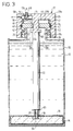
- the present invention comprises a container 10 for storing a quantity of liquid 12 to be cooled and/or gasified before being dispensed, an adsorbent 14 for adsorbing gas such as, for example, carbon dioxide to be used during said cooling and/or gasifying process and a re-sealable cap shown generally at 17.
- the adsorbent 14 is encased in an outer casing 16 formed of, for example plastic material.
- the casing 16 is provided with an outlet 18 and a releasing means in the form of re-sealable valve 20 for allowing or inhibiting the flow of adsorbed gas from the adsorbent.
- Valve 20 is operably connected to cap 17 via linking member 22 which extends through the body of liquid 12 within the container.
- the cap itself comprises a first inner portion 24 releasably connected to the container by, for example, screw thread 26 and a second outer portion 28 operably connected to the first portion 24 in a manner to be described in detail later herein and moveable relative thereto between first, second and third positions illustrated by Figures 5A to 5C respectively.
- the inner portion 24 includes a plurality of axially projecting and circumferentially spaced detents 30 projecting from an outer surface 32 and a central aperture 34 the function of which will be described in detail later herein.
- the first detents 30 are spatially positioned for operable connection with corresponding second detents 36 projecting from an inner surface 38 of outer portion 28.
- the second detents 36 are moveable with the second portion of the cap between said first position ( Figure 5A) in which they lie between the first detents and are not engaged therewith, said second position ( Figure 5B) in which they are axially displaced relative to the first detents 30 and are engaged with and retained in said position by said first detents 30, and said third position in which said second detents abut against said first detents 30 and facilitate rotational movement thereof upon rotational movement of said second portion.
- This last position allows for removal of cap 17 from container 10.
- a seal shown in, for example, the form of an O ring 40 (best seen in Figures 1 - 3) is provided for sealing any gap between inner and outer portions 24,28 respectively.
- the seal is preferably located within a region having an axially extending groove 42 along which the seal may slide as outer portion 28 is moved between its axially displaced positions.
- a chamber 44 is formed between said first and said second cap portions 24, 28 and is operably linked for the flow of gas from the interior 10A of container 10 via aperture 34 in inner portion 24.
- a spring 43 biases the outer portion 28 away from the inner portion.
- the outer portion 28 is further provided with a gas outlet and pressure release valve 48 for allowing the flow of gas to atmosphere from within chamber 44.
- a sprung loaded arrangement as illustrated in Figures 1 - 3 can be employed to give a visual indication of when the valve is open and, hence, gas is being vented to atmosphere.
- This arrangement includes a projection 50 which, in operation stands proud of an upper surface 28A of the cap whenever the valve is open.
- the valve includes a valve seat 52 and is sprung loaded by spring 54 to bias the valve such that seat 52 obturates outlet 46 as shown in Figure 1.
- gas pressure within chamber 44 acts to open valve 48 and allow excess gas to escape to atmosphere via chamber 56 and outlet 58.
- Outer portion 28 further includes an actuation means in the form of plunger 60 depending from bottom surface 28b.
- Plunger 60 extends through chamber 44 and opening 34 before terminating at a point adjacent an upper end 22a of link member 22.
- Aperture 34 is suitably sized so as to allow for the escape of gas between plunger 60 and inner portion 24. If necessary, a plurality of cut-outs 62 may be provided around aperture 34 so as to enlarge the gas escape path.
- Distal end of plunger 60 defines an abutment surface 60a for abutment against end 22a of link member 22.
- a pellet of adsorbent 14 is deposited within the container 10 and link member 22 positioned for engagement with valve 20 and plunger 60.
- the link member 22 may be engaged with valve 20 via a screw thread (not shown) or might simply rest on an upper surface thereof and be supported by frictional engagement therewith.
- the upper end 22a of link member 22 extends into the outlet 10b of container 10 and is effectively located therein by inner walls 10c of the outlet. If necessary, upper end 22a may be further located within opening 10b by means of one or more location arms 62 shown in Figure 1. Gas pressure from within casing 16 acts against surface 64 of valve 20 to maintain the valve in a closed position.
- a spring 66 may be incorporated to maintain the valve in its closed position.
- detents 30 and 36 lie in substantially the same plane and a small gap G exists between plunger 60 and link member 22. Consequently, the valve 20 is maintained in its closed position by the pressure within casing 16 and/or spring 66. With the cap 17 in this position the container 10 and its contents 12 may be stored and/or transported without disturbing the contents thereof.
- FIG. 2 and Figure 5b A second position of cap 17 is shown in Figure 2 and Figure 5b from which it will be appreciated that outer portion 28 is depressed downwardly in the direction of arrow D such that detents 30 pass between detents 36 and are then turned radially and the detents lie one on top of one another before the outer portion 28 is released and spring 43 biases the outer portion 28 upwardly such that the detents engage each other and the plunger 60 is maintained in a depressed position.
- valve 20 is caused to open and gas is allowed to escape from container 16 and into the main body of liquid 12 contained within container 10.
- valve 48 will operate upon build up of a predetermined pressure. This pressure is matched to that associated with sufficient gasification of the liquid for the purpose which it is intended. For example, a carbonated beverage would employ carbon dioxide gas released as bubbles into the liquid 12 such that a fizzy carbonated beverage is produced prior to dispensing. The pressure associated with sufficient carbonation is therefore important to the consumer's enjoyment of the beverage and should therefore be accurately determined for each and every beverage.
- cap 17 by rotating outer portion 28 in the direction of arrow O in Figure 5c such that the detents 30, 36 disengage one another and return to the same plane before engaging one another once again such that rotation of outer portion 28 causes rotation of inner portion 24 and disengagement of screw thread 26.
- the cap 17 may then be removed and the beverage 12 dispensed.
- the outer casing 16 could be made of a thin sheet of a thermally-conductive material, such as aluminium or aluminium alloy, and the outer casing could be contoured and/or provided with fins (not shown) or the like, as is known in the art, in order to assist heat transfer and thus the chilling effect.
- the outer casing 16 is shaped and configured so as to minimise the volume therein (so far as is consistent with the requirements to contain a predetermined amount of adsorbent and to permit gas to be adsorbed and desorbed thereby) whilst maximising its surface area. This not only optimises the chilling effect resulting from the adsorbent temperature drop, but also ensures that the outer casing 16 containing the adsorbent 14 does not displace any greater volume of beverage than is strictly necessary to achieve the desired gassifying and/or chilling effect.
- the outer casing 16 may be resiliently deformable, in order to allow easy insertion thereof into the container 10. This resilience is preferably sufficient to allow the inserted outer casing to expand within the container 10 so as to retain the outer casing 16 in position therein.
- One of the advantages of the present invention resides in its flexibility in respect of beverage gasification and/or chilling.
- the consumer can choose between gasification and gasification with cooling. Additionally, he can terminate one or other or both of said phases by early release of the cap.
- the carbonating step may be initiated any one of a number of times and any remaining adsorbed gas is maintained under pressure in casing 16 by re-sealable valve 20.
- the consumer need not carbonate the beverage at all and might simply choose to dispense the beverage in its stored state. Such a choice would be exercised by simply turning outer portion 28 in the direction of arrow O rather than depressing it and opening valve 20.
- a container as described above may also be provided with temperature reactive means adapted to give a visual indication of the temperature of the beverage.
- the temperature reactive means comprises a thermochromatic substance, such as a thermochromatic paint, or pigment, or thermochromatic liquid crystals, substances which would change colour according to their temperature and which, per se, are known in the art.
- a thermochromatic substance such as a thermochromatic paint, or pigment, or thermochromatic liquid crystals, substances which would change colour according to their temperature and which, per se, are known in the art.
- the thermochromatic substance would be in direct thermal contact with the beverage container, such that as the temperature of the beverage fell due to the operation of the chiller so would the temperature of the container and the thermochromatic substance, which substance would then change colour thus giving the consumer a visual indication that the beverage had been chilled and was ready to drink.
- thermochromatic substance is preferably applied directly to the outer surface of the beverage container, as indicated at 70 in Figure 1, not only so as more quickly and accurately to indicate any temperature change of the beverage therein but also so as to be more easily incorporated during the container manufacturing process.
- Drink cans for example, are ordinarily painted, and the addition of a further station on the can manufacturing line to apply thermochromatic paint or the like would be neither difficult nor expensive.
- thermochromatic substances could equally be applied in patterns and colours to provide a significant aesthetic appeal to a consumer; so as to produce an eye-catching design or slogan, for example, when the beverage or other fluid is sufficiently chilled.
- the present invention encompasses not only an apparatus for cooling and/or gasifying a liquid stored in a container, but also a container comprising such an apparatus.
- the principles of this invention could be employed with substances other than liquids - solid and semi-solid foodstuffs, for example, or pharmaceuticals, chemicals or the like. Similar principles could also be applicable where it is desired to gasify and heat a liquid.
Landscapes
- Engineering & Computer Science (AREA)
- Mechanical Engineering (AREA)
- Filling Or Discharging Of Gas Storage Vessels (AREA)
- Gas Separation By Absorption (AREA)
- Physical Or Chemical Processes And Apparatus (AREA)
- Devices For Dispensing Beverages (AREA)
- Separation Of Gases By Adsorption (AREA)
Claims (25)
- Einrichtung zum Kühlen und/oder Vergasen einer in einem Behälter (10) mit einem Auslaß (10b) gespeicherten Flüssigkeit (12), mit einem Adsorptionsmittel (14), um unter Druck eine Gasmenge aufzunehmen und zu adsorbieren, Verschlußmitteln zum Verschließen des adsorbierten Gases in dem Adsorptionsmittel, und Freigabemitteln (20) zum Freigeben von adsorbiertem Gas aus dem Adsorptionsmittel (14) in gesteuerter Weise und direkt in die genannte Flüssigkeit (12), derart, daß das freigesetzte Gas durch die Flüssigkeit (12) hindurchpassiert und dadurch die Flüssigkeit abkühlt und/oder vergast.
- Einrichtung nach Anspruch 1, wobei das Adsorptionsmittel (14) innerhalb des zu kühlenden und/oder zu vergasenden Flüssigkeitsvolumens (12) positioniert ist, und wobei die Freigabemittel ein wiederverschließbares Ventil (20) aufweisen, um die Strömung von adsorbierten Gas aus dem Adsorptionsmittel (14) zuzulassen oder zu sperren.
- Einrichtung nach Anspruch 2, mit Betätigungsmitteln (17, 22) zum Betätigen des Ventils (20).
- Einrichtung nach Anspruch 3, wobei die Betätigungsmittel außerhalb des Behälters (10) angeordnet sind, aber wirkungsmäßig mit dem innerhalb des Behälters (10) befindlichen Ventil (20) gekuppelt sind.
- Einrichtung nach Anspruch 4, wobei die Betätigungsmittel eine abnehmbare Kappe (17) aufweisen, die auch zum Abschließen der Flüssigkeit im Behälter (10) dient.
- Einrichtung nach Anspruch 5, wobei die Kappe eine Dreistellungskappe (17) ist, die in ihrer ersten Position den Behälter (10) verschließt und den Austritt von adsorbierten Gas verhindert, in ihrer zweiten Position Gas aus dem Adsorptionsmittel austreten und durch eine im Behälter (10) enthaltene Flüssigkeit (12) hindurchpassieren läßt, um dadurch die Flüssigkeit (12) abzukühlen und/oder zu vergasen, und in ihrer dritten Stellung das Abnehmen der Kappe (70) und folglich das Ausgeben der Flüssigkeit (12) aus dem Behälter (10) ermöglicht.
- Einrichtung nach Anspruch 6, wobei die Kappe (17) einen ersten inneren Teil (24), der lösbar mit dem Behälter (10) verbunden ist, und einen zweiten äußeren Teil (28) aufweist, der wirkungsmäßig mit dem ersten Teil (24) verbunden und relativ dazu zwischen der ersten, zweiten und dritten Stellung beweglich ist.
- Einrichtung nach Anspruch 7, wobei die Betätigungsmittel einen Teil der Kappe (17) selbst aufweisen und der genannte äußere Teil (28) axial zwischen einer ersten Position, in welcher er das Ventil (20) in geschlossener Position hält, und einer zweiten Position verschiebbar ist, in welcher er das Ventil (20) in offener Position hält.
- Einrichtung nach Anspruch 8, wobei die Betätigungsmittel (17, 22) weiter ein Kuppelglied (22) umfassen, das im Betrieb zwischen der Kappe (17) und dem Ventil (20) verläuft.
- Einrichtung nach Anspruch 9, wobei der zweite Teil der Kappe (17) eine Anschlagfläche aufweist, an welcher das Kuppelglied (22) anstößt, um damit axial verschoben zu werden und folglich das Ventil (20) zu betätigen.
- Einrichtung nach einem der Ansprüche 7 bis 10, wobei der genannte äußere Teil (28) axial relativ zum inneren Teil (24) zwischen der ersten, zweiten und dritten Position verschiebbar ist und weiter Haltemittel (36) zum Halten des zweiten Teils (28) in seiner zweiten Position bis zur Freigabe durch eine Bedienungsperson aufweist.
- Einrichtung nach Anspruch 11, wobei die Haltemittel eine Mehrzahl erster Nasen (30), die von einer Außenfläche (32) des ersten Teils (24) wegragen, und eine Mehrzahl von zweiten Nasen (36) aufweisen, die von einer Innenfläche (38) des zweiten Teils (28) wegragen, wobei die zweiten Nasen (36) mit dem zweiten Teil (28) der Kappe zwischen der ersten Position, in welcher sie zwischen den ersten Nasen (30) liegen und nicht damit zusammenwirken, der genannten zweiten Position, in welcher die zweiten Nasen (36) axial relativ zu den ersten Nasen (30) versetzt sind und mit den ersten Nasen (30) zusammenwirken und von diesen in dieser Position gehalten werden, und der genannten dritten Position beweglich sind, in welcher die zweiten Nasen (36) an den ersten Nasen (30) anliegen und deren Drehbewegung bei einer Drehbewegung des zweiten Teils ermöglichen und dadurch das Abnehmen der Kappe (17) im Behälter (10) ermöglichen.
- Einrichtung nach einem der Ansprüche 7 bis 12, mit einer zwischen dem ersten Kappenteil und dem zweiten Kappenteil (24, 28) gebildeten Kammer (44) und einem Kanal zwischen dem inneren des Behälters (10) und der Kammer (44) um das Einströmen des freigesetzten Gases in diese zu ermöglichen, wobei die Kammer (44) durch eine Dichtung (40) zwischen dem ersten und dem zweiten Teil (24, 28) der Kappe (17) gegen die Atmosphäre abgedichtet ist.
- Einrichtung nach Anspruch 13, mit einem Überdruckventil (48), um Gas in die Atmosphäre austreten zu lassen, wenn der Druck in der Kammer (44) einen vorgegebenen Wert übersteigt.
- Einrichtung nach Anspruch 14, wobei das Ventil (48) eine Sichtanzeige aufweist, daß das Ventil (48) geöffnet ist und das Gas in die Atmosphäre entlüftet wird.
- Einrichtung nach Anspruch 15, wobei die Sichtanzeige einen Vorsprung (50) aufweist, der beim Öffnen des Ventils (48) über die Außenfläche (28A) des zweiten Teils (28) der Kappe (17) vorsteht.
- Einrichtung nach einem der vorhergehenden Ansprüche, wobei das adsorbierte Gas Kohlendioxid ist.
- Einrichtung nach einem der vorhergehenden Ansprüche, wobei das Adsorptionsmittel (14) in einem Gehäuse (16) zur Anordnung in direktem Wärmekontakt mit der Flüssigkeit (12) enthalten ist.
- Einrichtung nach Anspruch 18, wobei das Gehäuse (16) elastisch verformbar ist.
- Einrichtung nach Anspruch 18 oder 19, wobei das Gehäuse (16) aus Aluminium oder einer Legierung hiervon gebildet ist.
- Flüssigkeitsspeicherbehälter mit einer Einrichtung nach einem der vorhergehenden Ansprüche.
- Flüssigkeitsspeicherbehälter nach Anspruch 21, mit auf Temperatur ansprechenden Mitteln zur Angabe einer Sichtanzeige der Flüssigkeitstemperatur.
- Flüssigkeitsspeicherbehälter nach Anspruch 22, wobei die auf Temperatur ansprechenden Mittel thermochromatische Farbe oder Pigment aufweisen.
- Flüssigkeitsspeicherbehälter nach Anspruch 22 oder 23, wobei die auf Temperatur ansprechenden Mittel eine thermochromatische Flüssigkristallanzeige oder -Schicht aufweisen.
- Flüssigkeitsspeicherbehälter nach einem der Ansprüche 22 bis 24, wobei die auf Temperatur ansprechenden Mittel an der Außenfläche des Behälters (10) angebracht sind.
Applications Claiming Priority (3)
| Application Number | Priority Date | Filing Date | Title |
|---|---|---|---|
| GB9612125A GB2314066B (en) | 1996-06-10 | 1996-06-10 | Apparatus for cooling and/or gassifying a liquid |
| GB9612125 | 1996-06-10 | ||
| PCT/GB1997/000045 WO1997047932A1 (en) | 1996-06-10 | 1997-01-08 | Apparatus for cooling and/or gassifying a liquid |
Publications (2)
| Publication Number | Publication Date |
|---|---|
| EP0904517A1 EP0904517A1 (de) | 1999-03-31 |
| EP0904517B1 true EP0904517B1 (de) | 1999-12-01 |
Family
ID=10795056
Family Applications (1)
| Application Number | Title | Priority Date | Filing Date |
|---|---|---|---|
| EP97900296A Expired - Lifetime EP0904517B1 (de) | 1996-06-10 | 1997-01-08 | Gerät zum kühlen und/oder zum vergasen einer flüssigkeit |
Country Status (15)
| Country | Link |
|---|---|
| US (1) | US6109057A (de) |
| EP (1) | EP0904517B1 (de) |
| JP (1) | JP2000512372A (de) |
| CN (1) | CN1127649C (de) |
| AT (1) | ATE187240T1 (de) |
| AU (1) | AU715145B2 (de) |
| CA (1) | CA2255872C (de) |
| DE (1) | DE69700881T2 (de) |
| ES (1) | ES2139435T3 (de) |
| GB (1) | GB2314066B (de) |
| GR (1) | GR3032738T3 (de) |
| NZ (1) | NZ332988A (de) |
| PT (1) | PT904517E (de) |
| TW (1) | TW345569B (de) |
| WO (1) | WO1997047932A1 (de) |
Families Citing this family (18)
| Publication number | Priority date | Publication date | Assignee | Title |
|---|---|---|---|---|
| DE19925646C2 (de) * | 1998-01-30 | 2001-12-20 | Eberhard Wistuba | Verwendung eines Stoffgemisches zur Desinfektion von Wasser und zur pH-Wert-Absenkung und Verfahren zur Kühlung |
| DE19922696A1 (de) * | 1999-05-18 | 1999-10-28 | Ronald Strasser | Fernwärmeversorgung durch Nutzung der Abwärme aus thermischen Kraftwerken und industriellen Prozessen |
| WO2001090666A1 (en) * | 2000-04-22 | 2001-11-29 | Jung Min Lee | Self-cooling liquid container |
| EP1359380A3 (de) * | 2003-06-04 | 2003-12-03 | Rainer Dominik Mayr-Hassler | Flüssigkeitsbehälter |
| US8005580B2 (en) | 2003-12-09 | 2011-08-23 | The Boeing Company | Aircraft galley systems and methods for managing electric power for aircraft galley systems |
| US7444830B2 (en) * | 2004-03-08 | 2008-11-04 | The Boeing Company | Aircraft galley carts and other insulated food storage units, and methods for their use |
| US7544915B2 (en) * | 2004-03-31 | 2009-06-09 | The Boeing Company | Aircraft galley carts and associated methods of manufacture |
| US7458441B2 (en) * | 2004-07-22 | 2008-12-02 | The Boeing Company | Securement latches and associated aircraft galley carts and methods |
| US20080083763A1 (en) * | 2006-10-06 | 2008-04-10 | Peter Nielsen | Drinking Vessel Dry Ice Filling Apparatus and Method |
| CN101948035B (zh) * | 2010-09-13 | 2013-03-13 | 周允平 | 饮料喷射的控制装置和容器结构及其饮料喷射的控制方法 |
| DE102011056052A1 (de) * | 2011-12-05 | 2013-06-06 | Krones Ag | Vorrichtung zur Verarbeitung eines Lebensmittelprodukts, bevorzugt zur Herstellung und/oder Abfüllung von Getränken, Komponente für eine solche Vorrichtung sowie Verfahren zur thermischen Überwachung von Komponenten |
| US9481503B2 (en) * | 2012-09-28 | 2016-11-01 | Pepsico, Inc. | Use of adsorber material to relieve vacuum in sealed container caused by cooling of heated contents |
| BR102014018459B1 (pt) * | 2014-07-28 | 2022-02-01 | Whirlpool S.A. | Torre de carbonatação para aparelhos dispensadores de bebidas |
| GB2546272A (en) * | 2016-01-12 | 2017-07-19 | Linde Ag | A system comprising a transportable gas supply cylinder for pressurised gas and a method of monitoring such a cylinder |
| CN106994620A (zh) * | 2016-09-23 | 2017-08-01 | 广州萨哲电子科技有限公司 | 一种用于金属加工的冷却液装置 |
| CN106994621A (zh) * | 2016-09-23 | 2017-08-01 | 广州萨哲电子科技有限公司 | 一种金属切削用的新型冷却液装置 |
| CN106994619A (zh) * | 2016-09-23 | 2017-08-01 | 广州萨哲电子科技有限公司 | 一种金属加工用的新型冷却液装置 |
| CN110770498A (zh) * | 2017-06-12 | 2020-02-07 | 恩特格里斯公司 | 用于试剂气体容器的热变色指示器 |
Family Cites Families (14)
| Publication number | Priority date | Publication date | Assignee | Title |
|---|---|---|---|---|
| US3642059A (en) * | 1969-06-30 | 1972-02-15 | Leonard Greiner | Heating and cooling unit |
| US3881321A (en) * | 1970-02-24 | 1975-05-06 | Drackett Co | Self-cooling disposable liquid container |
| US4025655A (en) * | 1974-07-15 | 1977-05-24 | The Procter & Gamble Company | Beverage carbonation devices |
| US4147808A (en) * | 1976-11-08 | 1979-04-03 | The Procter & Gamble Company | Beverage carbonation device and process |
| US4126016A (en) * | 1977-07-27 | 1978-11-21 | Leonard Greiner | Vacuum interconnect for heating and cooling unit |
| US4736599A (en) * | 1986-12-12 | 1988-04-12 | Israel Siegel | Self cooling and self heating disposable beverage cans |
| US4928495A (en) * | 1989-06-22 | 1990-05-29 | Israel Siegel | Self cooling and self heating container |
| JP2596169B2 (ja) * | 1990-04-12 | 1997-04-02 | 松下電器産業株式会社 | 冷却器 |
| US5079932A (en) * | 1991-01-30 | 1992-01-14 | Israel Siegel | Direct sorption self-cooling beverage container |
| AU6652894A (en) * | 1993-05-04 | 1994-11-21 | Christian Bizzocchi | Device for instantly cooling a liquid substance of variable consistency |
| FR2708724B1 (fr) * | 1993-07-29 | 1995-10-13 | Boye Sa Manuf Vetements Paul | Production de froid par adsoption/desorption de dioxyde de carbone avec utilisation de fibres de carbone activé ou de charbon actif comme matière adsorbante. |
| WO1995014898A1 (en) * | 1993-11-29 | 1995-06-01 | Mayekawa Mfg. Co., Ltd. | Adsorption type cooling apparatus, method of controlling cold output of same, and fin type adsorbent heat exchanger for use in same |
| FR2719367B1 (fr) * | 1994-04-27 | 1996-06-21 | Boye Sa Manuf Vetements Paul | Procédé et dispositif frigorigènes. |
| GB9513606D0 (en) * | 1995-07-04 | 1995-09-06 | Boc Group Plc | Apparatus for chilling fluids |
-
1996
- 1996-06-10 GB GB9612125A patent/GB2314066B/en not_active Expired - Fee Related
-
1997
- 1997-01-08 ES ES97900296T patent/ES2139435T3/es not_active Expired - Lifetime
- 1997-01-08 CA CA002255872A patent/CA2255872C/en not_active Expired - Fee Related
- 1997-01-08 DE DE69700881T patent/DE69700881T2/de not_active Expired - Fee Related
- 1997-01-08 CN CN97195422A patent/CN1127649C/zh not_active Expired - Fee Related
- 1997-01-08 US US09/194,958 patent/US6109057A/en not_active Expired - Fee Related
- 1997-01-08 PT PT97900296T patent/PT904517E/pt unknown
- 1997-01-08 WO PCT/GB1997/000045 patent/WO1997047932A1/en not_active Ceased
- 1997-01-08 JP JP10501329A patent/JP2000512372A/ja not_active Ceased
- 1997-01-08 AU AU13885/97A patent/AU715145B2/en not_active Ceased
- 1997-01-08 EP EP97900296A patent/EP0904517B1/de not_active Expired - Lifetime
- 1997-01-08 AT AT97900296T patent/ATE187240T1/de not_active IP Right Cessation
- 1997-01-08 NZ NZ332988A patent/NZ332988A/xx unknown
- 1997-10-28 TW TW086115966A patent/TW345569B/zh active
-
2000
- 2000-02-23 GR GR20000400437T patent/GR3032738T3/el not_active IP Right Cessation
Also Published As
| Publication number | Publication date |
|---|---|
| PT904517E (pt) | 2000-04-28 |
| US6109057A (en) | 2000-08-29 |
| JP2000512372A (ja) | 2000-09-19 |
| AU715145B2 (en) | 2000-01-20 |
| GR3032738T3 (en) | 2000-06-30 |
| DE69700881D1 (de) | 2000-01-05 |
| GB9612125D0 (en) | 1996-08-14 |
| TW345569B (en) | 1998-11-21 |
| EP0904517A1 (de) | 1999-03-31 |
| ATE187240T1 (de) | 1999-12-15 |
| NZ332988A (en) | 2000-05-26 |
| CN1127649C (zh) | 2003-11-12 |
| ES2139435T3 (es) | 2000-02-01 |
| GB2314066A (en) | 1997-12-17 |
| WO1997047932A1 (en) | 1997-12-18 |
| GB2314066B (en) | 1999-08-04 |
| CA2255872A1 (en) | 1997-12-18 |
| CA2255872C (en) | 2004-08-10 |
| DE69700881T2 (de) | 2000-05-25 |
| CN1221485A (zh) | 1999-06-30 |
| AU1388597A (en) | 1998-01-07 |
Similar Documents
| Publication | Publication Date | Title |
|---|---|---|
| CA2255872C (en) | Apparatus for cooling and/or gassifying a liquid | |
| US6854595B2 (en) | Container closure containing a mix | |
| US5692381A (en) | Apparatus for chilling fluids | |
| US6962254B2 (en) | Universal bottle cap | |
| CN103068718B (zh) | 吸收啤酒配给系统的推进剂气体的方法 | |
| US3987643A (en) | Thermodynamic beverage cooling unit | |
| AU734931B2 (en) | Self-cooling beverage and food container and manufacturing method | |
| US4739901A (en) | Apparatus for use in dispensing fluid from a container | |
| JPH01124575A (ja) | 自冷容器 | |
| CA2128687A1 (en) | Self-cooling fluid container | |
| JPH032755B2 (de) | ||
| US6530235B2 (en) | Self-chilling portable beverage container assembly, and method | |
| WO1996009507A2 (en) | Beverage container | |
| EP2444365A1 (de) | Abfüllverfahren einer Druckerzeugungsvorrichtung | |
| CA1224763A (en) | Method and apparatus for making a carbonated beverage | |
| US1933135A (en) | h barthelmes | |
| MXPA97009124A (en) | Container for beverages and foods of natural cooling and manufacturing method of mi | |
| WO2016168575A1 (en) | Food or beverage container having heat exchange unit internally thereof and thermochromic material on outer surface to indicate temperature change | |
| MXPA99006158A (en) | Apparatus for chilling fluids |
Legal Events
| Date | Code | Title | Description |
|---|---|---|---|
| PUAI | Public reference made under article 153(3) epc to a published international application that has entered the european phase |
Free format text: ORIGINAL CODE: 0009012 |
|
| 17P | Request for examination filed |
Effective date: 19981116 |
|
| AK | Designated contracting states |
Kind code of ref document: A1 Designated state(s): AT BE CH DE DK ES FI FR GB GR IE IT LI LU NL PT SE |
|
| GRAG | Despatch of communication of intention to grant |
Free format text: ORIGINAL CODE: EPIDOS AGRA |
|
| GRAG | Despatch of communication of intention to grant |
Free format text: ORIGINAL CODE: EPIDOS AGRA |
|
| GRAH | Despatch of communication of intention to grant a patent |
Free format text: ORIGINAL CODE: EPIDOS IGRA |
|
| RTI1 | Title (correction) |
Free format text: APPARATUS FOR COOLING AND/OR GASIFYING A LIQUID |
|
| 17Q | First examination report despatched |
Effective date: 19990511 |
|
| RTI1 | Title (correction) |
Free format text: APPARATUS FOR COOLING AND/OR GASIFYING A LIQUID |
|
| GRAH | Despatch of communication of intention to grant a patent |
Free format text: ORIGINAL CODE: EPIDOS IGRA |
|
| GRAA | (expected) grant |
Free format text: ORIGINAL CODE: 0009210 |
|
| AK | Designated contracting states |
Kind code of ref document: B1 Designated state(s): AT BE CH DE DK ES FI FR GB GR IE IT LI LU NL PT SE |
|
| REF | Corresponds to: |
Ref document number: 187240 Country of ref document: AT Date of ref document: 19991215 Kind code of ref document: T |
|
| ITF | It: translation for a ep patent filed | ||
| REG | Reference to a national code |
Ref country code: CH Ref legal event code: EP |
|
| REF | Corresponds to: |
Ref document number: 69700881 Country of ref document: DE Date of ref document: 20000105 |
|
| REG | Reference to a national code |
Ref country code: IE Ref legal event code: FG4D |
|
| REG | Reference to a national code |
Ref country code: ES Ref legal event code: FG2A Ref document number: 2139435 Country of ref document: ES Kind code of ref document: T3 |
|
| REG | Reference to a national code |
Ref country code: CH Ref legal event code: NV Representative=s name: RIEDERER HASLER & PARTNER PATENTANWAELTE AG |
|
| ET | Fr: translation filed | ||
| REG | Reference to a national code |
Ref country code: PT Ref legal event code: SC4A Free format text: AVAILABILITY OF NATIONAL TRANSLATION Effective date: 20000125 |
|
| REG | Reference to a national code |
Ref country code: DK Ref legal event code: T3 |
|
| PLBE | No opposition filed within time limit |
Free format text: ORIGINAL CODE: 0009261 |
|
| STAA | Information on the status of an ep patent application or granted ep patent |
Free format text: STATUS: NO OPPOSITION FILED WITHIN TIME LIMIT |
|
| 26N | No opposition filed | ||
| REG | Reference to a national code |
Ref country code: GB Ref legal event code: IF02 |
|
| PGFP | Annual fee paid to national office [announced via postgrant information from national office to epo] |
Ref country code: AT Payment date: 20061221 Year of fee payment: 11 |
|
| PGFP | Annual fee paid to national office [announced via postgrant information from national office to epo] |
Ref country code: PT Payment date: 20061222 Year of fee payment: 11 |
|
| PGFP | Annual fee paid to national office [announced via postgrant information from national office to epo] |
Ref country code: NL Payment date: 20070124 Year of fee payment: 11 |
|
| PGFP | Annual fee paid to national office [announced via postgrant information from national office to epo] |
Ref country code: GB Payment date: 20070125 Year of fee payment: 11 |
|
| PGFP | Annual fee paid to national office [announced via postgrant information from national office to epo] |
Ref country code: ES Payment date: 20070126 Year of fee payment: 11 |
|
| PGFP | Annual fee paid to national office [announced via postgrant information from national office to epo] |
Ref country code: SE Payment date: 20070129 Year of fee payment: 11 Ref country code: CH Payment date: 20070129 Year of fee payment: 11 Ref country code: IE Payment date: 20070129 Year of fee payment: 11 |
|
| PGFP | Annual fee paid to national office [announced via postgrant information from national office to epo] |
Ref country code: FI Payment date: 20070130 Year of fee payment: 11 |
|
| PGFP | Annual fee paid to national office [announced via postgrant information from national office to epo] |
Ref country code: DK Payment date: 20070131 Year of fee payment: 11 |
|
| PGFP | Annual fee paid to national office [announced via postgrant information from national office to epo] |
Ref country code: LU Payment date: 20070201 Year of fee payment: 11 |
|
| PGFP | Annual fee paid to national office [announced via postgrant information from national office to epo] |
Ref country code: DE Payment date: 20070228 Year of fee payment: 11 |
|
| PGFP | Annual fee paid to national office [announced via postgrant information from national office to epo] |
Ref country code: BE Payment date: 20070301 Year of fee payment: 11 |
|
| PGFP | Annual fee paid to national office [announced via postgrant information from national office to epo] |
Ref country code: IT Payment date: 20070521 Year of fee payment: 11 |
|
| PGFP | Annual fee paid to national office [announced via postgrant information from national office to epo] |
Ref country code: GR Payment date: 20070129 Year of fee payment: 11 |
|
| PGFP | Annual fee paid to national office [announced via postgrant information from national office to epo] |
Ref country code: FR Payment date: 20070117 Year of fee payment: 11 |
|
| REG | Reference to a national code |
Ref country code: PT Ref legal event code: MM4A Free format text: LAPSE DUE TO NON-PAYMENT OF FEES Effective date: 20080708 |
|
| BERE | Be: lapsed |
Owner name: THE *BOC GROUP P.L.C. Effective date: 20080131 |
|
| REG | Reference to a national code |
Ref country code: CH Ref legal event code: PL |
|
| REG | Reference to a national code |
Ref country code: DK Ref legal event code: EBP |
|
| EUG | Se: european patent has lapsed | ||
| GBPC | Gb: european patent ceased through non-payment of renewal fee |
Effective date: 20080108 |
|
| NLV4 | Nl: lapsed or anulled due to non-payment of the annual fee |
Effective date: 20080801 |
|
| REG | Reference to a national code |
Ref country code: IE Ref legal event code: MM4A |
|
| PG25 | Lapsed in a contracting state [announced via postgrant information from national office to epo] |
Ref country code: PT Free format text: LAPSE BECAUSE OF NON-PAYMENT OF DUE FEES Effective date: 20080708 Ref country code: NL Free format text: LAPSE BECAUSE OF NON-PAYMENT OF DUE FEES Effective date: 20080801 Ref country code: LI Free format text: LAPSE BECAUSE OF NON-PAYMENT OF DUE FEES Effective date: 20080131 Ref country code: FI Free format text: LAPSE BECAUSE OF NON-PAYMENT OF DUE FEES Effective date: 20080108 Ref country code: DE Free format text: LAPSE BECAUSE OF NON-PAYMENT OF DUE FEES Effective date: 20080801 Ref country code: CH Free format text: LAPSE BECAUSE OF NON-PAYMENT OF DUE FEES Effective date: 20080131 |
|
| PG25 | Lapsed in a contracting state [announced via postgrant information from national office to epo] |
Ref country code: AT Free format text: LAPSE BECAUSE OF NON-PAYMENT OF DUE FEES Effective date: 20080108 |
|
| REG | Reference to a national code |
Ref country code: FR Ref legal event code: ST Effective date: 20081029 |
|
| PG25 | Lapsed in a contracting state [announced via postgrant information from national office to epo] |
Ref country code: GB Free format text: LAPSE BECAUSE OF NON-PAYMENT OF DUE FEES Effective date: 20080108 |
|
| PG25 | Lapsed in a contracting state [announced via postgrant information from national office to epo] |
Ref country code: SE Free format text: LAPSE BECAUSE OF NON-PAYMENT OF DUE FEES Effective date: 20080109 Ref country code: IE Free format text: LAPSE BECAUSE OF NON-PAYMENT OF DUE FEES Effective date: 20080108 Ref country code: DK Free format text: LAPSE BECAUSE OF NON-PAYMENT OF DUE FEES Effective date: 20080131 |
|
| PG25 | Lapsed in a contracting state [announced via postgrant information from national office to epo] |
Ref country code: BE Free format text: LAPSE BECAUSE OF NON-PAYMENT OF DUE FEES Effective date: 20080131 |
|
| REG | Reference to a national code |
Ref country code: ES Ref legal event code: FD2A Effective date: 20080109 |
|
| PG25 | Lapsed in a contracting state [announced via postgrant information from national office to epo] |
Ref country code: FR Free format text: LAPSE BECAUSE OF NON-PAYMENT OF DUE FEES Effective date: 20080131 |
|
| PG25 | Lapsed in a contracting state [announced via postgrant information from national office to epo] |
Ref country code: GR Free format text: LAPSE BECAUSE OF NON-PAYMENT OF DUE FEES Effective date: 20080804 |
|
| PG25 | Lapsed in a contracting state [announced via postgrant information from national office to epo] |
Ref country code: ES Free format text: LAPSE BECAUSE OF NON-PAYMENT OF DUE FEES Effective date: 20080109 |
|
| PG25 | Lapsed in a contracting state [announced via postgrant information from national office to epo] |
Ref country code: IT Free format text: LAPSE BECAUSE OF NON-PAYMENT OF DUE FEES Effective date: 20080108 |
|
| PG25 | Lapsed in a contracting state [announced via postgrant information from national office to epo] |
Ref country code: LU Free format text: LAPSE BECAUSE OF NON-PAYMENT OF DUE FEES Effective date: 20080108 |