EP0904688B1 - Melkanlage - Google Patents
Melkanlage Download PDFInfo
- Publication number
- EP0904688B1 EP0904688B1 EP19980203182 EP98203182A EP0904688B1 EP 0904688 B1 EP0904688 B1 EP 0904688B1 EP 19980203182 EP19980203182 EP 19980203182 EP 98203182 A EP98203182 A EP 98203182A EP 0904688 B1 EP0904688 B1 EP 0904688B1
- Authority
- EP
- European Patent Office
- Prior art keywords
- milk
- measuring device
- installation
- sensor
- passage
- Prior art date
- Legal status (The legal status is an assumption and is not a legal conclusion. Google has not performed a legal analysis and makes no representation as to the accuracy of the status listed.)
- Expired - Lifetime
Links
- 238000009434 installation Methods 0.000 title claims description 20
- 239000008267 milk Substances 0.000 claims description 57
- 235000013336 milk Nutrition 0.000 claims description 57
- 210000004080 milk Anatomy 0.000 claims description 57
- 238000005259 measurement Methods 0.000 claims description 30
- 210000002445 nipple Anatomy 0.000 claims description 12
- 210000000481 breast Anatomy 0.000 claims description 10
- 238000011109 contamination Methods 0.000 claims description 5
- 244000144972 livestock Species 0.000 claims description 2
- 230000000063 preceeding effect Effects 0.000 claims 3
- 241000283690 Bos taurus Species 0.000 description 15
- 208000004396 mastitis Diseases 0.000 description 4
- 230000005856 abnormality Effects 0.000 description 3
- 239000000203 mixture Substances 0.000 description 3
- 238000010276 construction Methods 0.000 description 2
- 238000003745 diagnosis Methods 0.000 description 2
- 241001465754 Metazoa Species 0.000 description 1
- 239000004020 conductor Substances 0.000 description 1
- 238000003977 dairy farming Methods 0.000 description 1
- 208000037265 diseases, disorders, signs and symptoms Diseases 0.000 description 1
- 230000000694 effects Effects 0.000 description 1
- 230000005802 health problem Effects 0.000 description 1
Images

Classifications
-
- A—HUMAN NECESSITIES
- A01—AGRICULTURE; FORESTRY; ANIMAL HUSBANDRY; HUNTING; TRAPPING; FISHING
- A01J—MANUFACTURE OF DAIRY PRODUCTS
- A01J5/00—Milking machines or devices
- A01J5/013—On-site detection of mastitis in milk
- A01J5/0133—On-site detection of mastitis in milk by using electricity, e.g. conductivity or capacitance
-
- A—HUMAN NECESSITIES
- A01—AGRICULTURE; FORESTRY; ANIMAL HUSBANDRY; HUNTING; TRAPPING; FISHING
- A01J—MANUFACTURE OF DAIRY PRODUCTS
- A01J5/00—Milking machines or devices
- A01J5/013—On-site detection of mastitis in milk
- A01J5/0138—On-site detection of mastitis in milk by using temperature
Definitions
- the present invention relates to an installation for milking livestock.
- Such an installation is known from the patent application DD 221635 wherein such a measuring device comprises a passage for the main flow of milked milk and a chamber for measurements next thereto, wherein electrodes are arranged in the chamber to perform a measurement as sensor in order to determine the conductivity of the milk.
- a measuring device comprises a passage for the main flow of milked milk and a chamber for measurements next thereto, wherein electrodes are arranged in the chamber to perform a measurement as sensor in order to determine the conductivity of the milk.
- EP-A-0.137.367 discloses a passage and a measurement chamber next thereto, where a relatively large portion of the main flow of milk through the conduit, that interconnects the milk cup and the measuring device, is diverted into the measurement chamber thereof.
- a drawback of the known art is that turbulences in the flow, both in the main flow and as a result in the chamber, cause unintended fluctuations in the measurement result obtained with the measuring device. These fluctuations make the obtained measurement result unreliable and there is the danger as such of a diagnosis being made that a cow for milking may or may not be healthy, which may then be incorrect. Moreover, in an overflow construction milk from previously milked cows may affect a measurement at a later time, thereby endangering the correctness of the obtained results.
- the invention has for its object to at least diminish and preferably obviate the above stated drawback, and an installation is provided for this purpose which is distinguished by the features of claim 1.
- the design according to the invention displays an appearance similar to that of for instance a petrol filter, while a passage of constant dimensions relative to those of the conduit is maintained in the interior thereof. Simultaneously with feed of milked milk through the passage, "bypass" of a small quantity of the milked milk occurs for performing of the desired measurements thereon.
- the bypass milk is continually replaced in order to obtain instantaneous measurement results for milk milked at any relevant moment without being affected by milk from previously milked animals.
- a milking installation has at least one of the properties that the measuring device comprises at least one additional sensor for measuring the temperature of milked milk and that the measuring device comprises at least one additional sensor for measuring the composition of milked milk.
- the two measures separately or in combination, increases the efficiency of particularly the measuring device in the milking installation by increasing the amount of measurement data that is obtained in reliable manner and serves during milking to monitor a number of aspects which are of importance in dairy farming.
- a second embodiment of an installation according to the present invention has the property that the measuring device comprises at least one compensation sensor to compensate for contamination of the measuring device.
- contamination by milk remnants can, among other factors, also have a disturbing influence on obtained measurement results. This can be avoided in relatively simple manner by arranging the compensation sensor or compensation sensors.
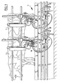
- the milking installation 1 shown in fig. 1 comprises a fence 2 for guiding cows 3.
- the cows are milked with milking installation 1, for which purpose teat cups 4 are arranged on the teats of the udders 5 of cows 3.
- Teat cups 4 are connected to milk collectors 7 by means of conduits 6.
- Milk collectors 7 are in turn connected via a hose 8 to a collective drainage conduit 9, via which drainage conduit 9 milked milk is drained to a central container or tank, which is not shown here.
- measuring devices 10 Arranged in conduits 6 between teat cups 4 and milk collectors 7 are measuring devices 10 with which measurements are carried out on milked milk. This substantially constitutes measurement of the conductivity and quality of the milk, this forming an indication as to whether or not there are abnormalities, such as for instance mastitis, which is an undesirable disorder of the cow. Because the measuring devices 10 are each arranged in one of the conduits 6 between the individual teat cups 4 and milk collectors 7, the milk from a quarter of the udder of a cow 3 is subjected to the measurement in reliable manner without this measurement being influenced by milk coming from the other quarters of the udder of the cow. It can therefore be determined for each quarter of the udder 5 of cow 3 whether there is any abnormality such as mastitis.
- the other components which are not further described are typical in the art and serve inter alia for control of teat cups 4 and connection of measuring devices 10 to a computer (not shown) in which the electrical signals originating from measuring devices 10 are processed in order to carry out the milk condition/milk quality diagnosis.
- a computer not shown
- the milk coming from this quarter of the udder 5 of cow 3 is preferably drained separately or this quarter of the udders 5 of cows 3 is milked separately.
- the measuring device comprises a housing designed as sleeve 11 having on the infeed side thereof an input designed as input socket 12 and on the outfeed side thereof an output designed as output socket 13.
- Sleeve 11 herein forms in the interior thereof a widened part relative to the cross-section of conduit 6 available for through-feed of milked milk and connected to input socket 12 and output socket 13.
- Milk flowing in the direction of arrow A into measuring device 10 follows for the greater part a passage formed by tube 18 arranged in the interior of sleeve 11.
- Tube 18 is held in place by means of ribs 19 so that it lies in line with both input socket 12 and output socket 13.
- Tube 18 is also provided with flange 20 at the bottom in the drawing.
- measuring chamber 14 Formed between the exterior of tube 18 and the interior of sleeve 11 is measuring chamber 14 into which during use of the measuring device 10 milk flows which does not flow through the tube 18 forming the passage.
- the milked milk herein enters measuring chamber 14 via an inlet opening designed as lateral passage 15.
- the speed of movement of the milked milk will decrease markedly here relative to that of the milk flowing through the tube 18 forming the passage as a consequence of the design of outlet openings for draining of milk from measuring chamber 14, which are arranged as relatively small holes 16 in flange 20.
- tube 18 corresponds closely with the inner diameter of the conduits 6 in which measuring device 10 is arranged, turbulence possibly occurring close to lateral passage 15 is minimized, wherein sufficient milk nevertheless reaches measuring chamber 14 to perform a reliable measurement.
- turbulence of the milked milk in measuring chamber 14 is further reduced by making use of relatively small holes 16 as outlet opening out of measuring chamber 14. The milk flows in undisturbed manner such that the measurement result remains optimally reliable.
- the measurement is performed using sensors designed as electrodes 17.
- sensors are provided for a number of separate measurements.
- measurement of the conductivity of milked milk takes place in measuring chamber 14 so as to assess on the basis thereof whether mastitis is present.
- a sensor is further arranged for measuring the temperature of the milked milk and a sensor is arranged for measuring the composition of the milked milk.
- Each of the above stated measurement results provides an indication as to the condition of the cow or the quality of the milked milk, such as for instance the fat and protein content.
- a sensor is moreover arranged which functions as compensation sensor in order to compensate for contamination of the measuring device and in particular the electrodes therein. Use is made for this purpose of an algorithm which is performed in the above mentioned computer (not shown) with the measurement results originating from the sensors.
- the measurement results from the compensation sensor can herein be used to compensate for contamination.
- the measuring device 10 shown in fig. 2 which the milk enters at the top in the direction of arrow A is otherwise formed from two parts which connect onto each other, wherein measuring chamber 14 is arranged in the upper half 22 and wherein a space is available in the lower half 23 to bring together again the milk flowing through tube 18 and the milk flowing through measuring chamber 14, this milk exiting into this space through holes 16.
- Measuring chamber 14 and this space for bringing together the two milk flows are separated by means of flange 20 which forms part of the upper half of measuring device 10 and in which holes 16 are arranged, and a lower flange 21 which forms part of the lower half 23 of measuring device 10 and in which holes (not shown) are also arranged corresponding with holes 16.
- the measuring device 10 formed in this manner from two components is particularly suitable in the sense that the electrical conductors running to electrodes 17 can be arranged between flange 20 and second flange 21 in order to effect a connection to the computer device (not shown).
- a simple configuration is moreover provided in this manner, wherein an optimally reliable measurement can be realized.
Landscapes
- Life Sciences & Earth Sciences (AREA)
- Animal Husbandry (AREA)
- Environmental Sciences (AREA)
- Investigating Or Analyzing Materials By The Use Of Electric Means (AREA)
Claims (8)
- Anlage zum Melken von Vieh (3), aufweisend:wobei eine Meßvorrichtung in jeder der Leitungen (6) angeordnet ist, und dadurch gekennzeichnet, daß die Meßvorrichtung einen Durchlaß für gemolkene Milch aufweist, mit einer Querschnittsabmessung, die im wesentlichen gleich zu derjenigen der Leitung (6) ist, und wobei die Meßvorrichtung ein Gehäuse (22, 23) aufweist, das einen Einlaß zum Verbinden mit der Leitung (6) auf der Seite der Zitzenbecher und einen Auslaß zum Verbinden der Leitung (6) auf der Seite des Milchkollektors (7) besitzt, zwischen denen sich der Durchlaß erstreckt, und eine Meßkammer (14), die außerhalb des Durchlasses angeordnet ist, und in der der Sensor oder die Sensoren angeordnet ist/sind, und der eine Zuführöffnung (15) enthält, die mit dem Durchlaß nahe an dem Einlaß verbunden ist, und eine Auslaßöffnung (16), die mit dem Durchlaß nahe an dem Auslaß verbunden ist.eine Anzahl von Zitzenbechern (4) zum Anordnen auf Zitzen von Eutern (5);einen Milchkollektor (7) zum Sammeln von Milch, die von jedem der Zitzenbecher während des Melkvorgangs kommt, wobei die Zitzenbecher über Leitungen mit dem Milchkollektor verbunden sind; undwenigstens eine Meßvorrichtung (10) mit einem Sensor zum Messen während des Melkvorgangs von wenigstens der Leitfähigkeit der gemolkenen Milch,
- Anlage gemäß Anspruch 1, dadurch gekennzeichnet, daß die Meßvorrichtung wenigstens einen Kompensationssensor aufweist, um eine Kontamination der Meßvorrichtung zu kompensieren.
- Anlage gemäß Anspruch 1, dadurch gekennzeichnet, daß die Meßvorrichtung wenigstens einen zusätzlichen Sensor zur Messung der Temperatur der gemolkenen Milch aufweist.
- Anlage gemäß einem der vorhergehenden Ansprüche, dadurch gekennzeichnet, daß der Sensor oder die Sensoren zwischen der Zuführöffnung und der Auslaßöffnung angeordnet ist/sind.
- Anlage gemäß Anspruch 4, dadurch gekennzeichnet, daß der Sensor oder die Sensoren Elektroden sind, die sich längs davon zwischen der Zuführöffnung (15) und der Auslaßöffnung (16) erstrecken.
- Anlage gemäß einem der vorhergehenden Ansprüche, dadurch gekennzeichnet, daß der Durchlaß und die Ausführöffnung nahe an dem Auslaß in einer Mischkammer, die in dem Gehäuse angeordnet ist, die in einer offenen Verbindung mit dem Auslaß steht, einmünden.
- Anlage gemäß einem der vorhergehenden Ansprüche, dadurch gekennzeichnet, daß der Sensor oder die Sensoren mit einer Steuerung verbunden ist oder sind, die dazu angepaßt ist, eine Auswahl auf der Grundlage der Meßdaten von dem Sensor oder den Sensoren auszuführen, um die gemolkene Milch hindurch zu einem Produktionsbehälter zu führen, oder um sie auszustoßen.
- Meßvorrichtung, die zur Verwendung in einer Melkanlage gemäß einem oder mehr als einem der vorhergehenden Ansprüche gedacht ist.
Applications Claiming Priority (2)
| Application Number | Priority Date | Filing Date | Title |
|---|---|---|---|
| NL1007140 | 1997-09-26 | ||
| NL1007140A NL1007140C2 (nl) | 1997-09-26 | 1997-09-26 | Melkinstallatie. |
Publications (2)
| Publication Number | Publication Date |
|---|---|
| EP0904688A1 EP0904688A1 (de) | 1999-03-31 |
| EP0904688B1 true EP0904688B1 (de) | 2003-11-26 |
Family
ID=19765749
Family Applications (1)
| Application Number | Title | Priority Date | Filing Date |
|---|---|---|---|
| EP19980203182 Expired - Lifetime EP0904688B1 (de) | 1997-09-26 | 1998-09-22 | Melkanlage |
Country Status (4)
| Country | Link |
|---|---|
| EP (1) | EP0904688B1 (de) |
| DE (1) | DE69819993T2 (de) |
| DK (1) | DK0904688T3 (de) |
| NL (1) | NL1007140C2 (de) |
Families Citing this family (3)
| Publication number | Priority date | Publication date | Assignee | Title |
|---|---|---|---|---|
| WO2008118056A1 (en) * | 2007-03-23 | 2008-10-02 | Delaval Holding Ab | A device for measuring an electrical parameter in milk and a milking apparatus including such a device |
| NL2017993B1 (nl) * | 2016-12-14 | 2018-06-26 | Lely Patent Nv | Melksysteem |
| US12411119B2 (en) | 2022-02-18 | 2025-09-09 | Bovonic Limited | In-line sensor, milking cluster and associated methods |
Family Cites Families (4)
| Publication number | Priority date | Publication date | Assignee | Title |
|---|---|---|---|---|
| JPS6070021A (ja) | 1983-09-26 | 1985-04-20 | 東亜電波工業株式会社 | 搾乳装置 |
| DD221635A1 (de) * | 1983-11-18 | 1985-05-02 | Adl Der Ddr Fz F Tierproduktio | Vorrichtung zur messung und bewertung physiologischer parameter bei weiblichen saeugetieren |
| NL9101636A (nl) * | 1991-09-27 | 1993-04-16 | Lely Nv C Van Der | Werkwijze voor het automatisch melken van dieren. |
| GB2257008B (en) * | 1991-04-30 | 1994-11-09 | Sidney William Simpson | Sub clinical mastitis detector and excluder |
-
1997
- 1997-09-26 NL NL1007140A patent/NL1007140C2/nl not_active IP Right Cessation
-
1998
- 1998-09-22 DK DK98203182T patent/DK0904688T3/da active
- 1998-09-22 EP EP19980203182 patent/EP0904688B1/de not_active Expired - Lifetime
- 1998-09-22 DE DE1998619993 patent/DE69819993T2/de not_active Expired - Lifetime
Also Published As
| Publication number | Publication date |
|---|---|
| NL1007140C2 (nl) | 1999-03-29 |
| DE69819993T2 (de) | 2004-07-22 |
| EP0904688A1 (de) | 1999-03-31 |
| DE69819993D1 (de) | 2004-01-08 |
| DK0904688T3 (da) | 2004-01-05 |
Similar Documents
| Publication | Publication Date | Title |
|---|---|---|
| EP0836802B1 (de) | Verfahren und Gerät zum automatischen Melken von Tieren | |
| US7874263B2 (en) | Arrangement and method for milking a plurality of milking animals | |
| US8646411B2 (en) | Method and apparatus for milking animals having four teats | |
| US6378455B1 (en) | Intelligent claw | |
| Ordolff | Introduction of electronics into milking technology | |
| EP0628244B1 (de) | Verfahren zum Melken von Tieren und Vorrichtung zu deren Anwendung | |
| EP0748156B1 (de) | Milchsammelstück mit Sensoren zur Messung der komplexen Impedanz von Milch | |
| US9468191B2 (en) | Device for carrying out at least one measurement and for taking milk samples from a milking machine | |
| EP0223536A2 (de) | Automatische Melkanlagen und Melkverfahren | |
| EP1155610A2 (de) | Mengenmesser und damit ausgerüstete Vorrichtung zum Melken von Tieren | |
| EP0904688B1 (de) | Melkanlage | |
| RU2340171C2 (ru) | Вращающийся доильный блок с линиями для транспортировки | |
| US6971330B2 (en) | Method of and an apparatus for somatic cell count | |
| WO2004032608A1 (en) | A milking plant | |
| EP1297742B1 (de) | Verfahren zur Messwerterfassung während des automatischen Melkens eines Tieres | |
| US6776119B2 (en) | Device and method for separating milk from dairy animals | |
| US20030061994A1 (en) | Device and method for separating milk from a dairy animal | |
| EP1297741B1 (de) | Vorrichtung zum Melken von Tieren | |
| SE443285B (sv) | Apparat för diagnostisering av mlölksekretionssjukdomar | |
| RU2150190C1 (ru) | Устройство для доения коров и выпаивания телят | |
| GB2257008A (en) | Sub-clinical mastitis detector and excluder. | |
| WO2001095703A1 (en) | A method and an arrangement for milking an animal | |
| Vršková et al. | Survey of somatic cell counts and milk composition in bulk milk of ewes in dairy practice. | |
| WO2025010003A1 (en) | Arrangement and method for controlling milking vacuum levels | |
| SU1101206A1 (ru) | Молокомер |
Legal Events
| Date | Code | Title | Description |
|---|---|---|---|
| PUAI | Public reference made under article 153(3) epc to a published international application that has entered the european phase |
Free format text: ORIGINAL CODE: 0009012 |
|
| AK | Designated contracting states |
Kind code of ref document: A1 Designated state(s): CH DE DK FR GB IE IT LI SE |
|
| AX | Request for extension of the european patent |
Free format text: AL;LT;LV;MK;RO;SI |
|
| 17P | Request for examination filed |
Effective date: 19990928 |
|
| AKX | Designation fees paid |
Free format text: CH DE DK FR GB IE IT LI SE |
|
| 17Q | First examination report despatched |
Effective date: 20010903 |
|
| GRAH | Despatch of communication of intention to grant a patent |
Free format text: ORIGINAL CODE: EPIDOS IGRA |
|
| GRAS | Grant fee paid |
Free format text: ORIGINAL CODE: EPIDOSNIGR3 |
|
| GRAA | (expected) grant |
Free format text: ORIGINAL CODE: 0009210 |
|
| AK | Designated contracting states |
Kind code of ref document: B1 Designated state(s): CH DE DK FR GB IE IT LI SE |
|
| REG | Reference to a national code |
Ref country code: GB Ref legal event code: FG4D |
|
| REG | Reference to a national code |
Ref country code: CH Ref legal event code: EP |
|
| REG | Reference to a national code |
Ref country code: CH Ref legal event code: NV Representative=s name: ANDRE ROLAND CONSEILS EN PROPRIETE INTELLECTUELLE |
|
| REG | Reference to a national code |
Ref country code: DK Ref legal event code: T3 |
|
| REF | Corresponds to: |
Ref document number: 69819993 Country of ref document: DE Date of ref document: 20040108 Kind code of ref document: P |
|
| REG | Reference to a national code |
Ref country code: IE Ref legal event code: FG4D |
|
| REG | Reference to a national code |
Ref country code: SE Ref legal event code: TRGR |
|
| ET | Fr: translation filed | ||
| PLBE | No opposition filed within time limit |
Free format text: ORIGINAL CODE: 0009261 |
|
| STAA | Information on the status of an ep patent application or granted ep patent |
Free format text: STATUS: NO OPPOSITION FILED WITHIN TIME LIMIT |
|
| 26N | No opposition filed |
Effective date: 20040827 |
|
| REG | Reference to a national code |
Ref country code: FR Ref legal event code: PLFP Year of fee payment: 19 |
|
| PGFP | Annual fee paid to national office [announced via postgrant information from national office to epo] |
Ref country code: CH Payment date: 20160928 Year of fee payment: 19 Ref country code: IE Payment date: 20160927 Year of fee payment: 19 Ref country code: DK Payment date: 20160930 Year of fee payment: 19 Ref country code: GB Payment date: 20160927 Year of fee payment: 19 |
|
| PGFP | Annual fee paid to national office [announced via postgrant information from national office to epo] |
Ref country code: FR Payment date: 20160927 Year of fee payment: 19 Ref country code: SE Payment date: 20160930 Year of fee payment: 19 |
|
| PGFP | Annual fee paid to national office [announced via postgrant information from national office to epo] |
Ref country code: DE Payment date: 20160929 Year of fee payment: 19 |
|
| PGFP | Annual fee paid to national office [announced via postgrant information from national office to epo] |
Ref country code: IT Payment date: 20160927 Year of fee payment: 19 |
|
| REG | Reference to a national code |
Ref country code: DE Ref legal event code: R119 Ref document number: 69819993 Country of ref document: DE |
|
| REG | Reference to a national code |
Ref country code: DK Ref legal event code: EBP Effective date: 20170930 |
|
| REG | Reference to a national code |
Ref country code: CH Ref legal event code: PL |
|
| REG | Reference to a national code |
Ref country code: SE Ref legal event code: EUG |
|
| GBPC | Gb: european patent ceased through non-payment of renewal fee |
Effective date: 20170922 |
|
| REG | Reference to a national code |
Ref country code: IE Ref legal event code: MM4A |
|
| REG | Reference to a national code |
Ref country code: FR Ref legal event code: ST Effective date: 20180531 |
|
| PG25 | Lapsed in a contracting state [announced via postgrant information from national office to epo] |
Ref country code: GB Free format text: LAPSE BECAUSE OF NON-PAYMENT OF DUE FEES Effective date: 20170922 Ref country code: LI Free format text: LAPSE BECAUSE OF NON-PAYMENT OF DUE FEES Effective date: 20170930 Ref country code: CH Free format text: LAPSE BECAUSE OF NON-PAYMENT OF DUE FEES Effective date: 20170930 Ref country code: IE Free format text: LAPSE BECAUSE OF NON-PAYMENT OF DUE FEES Effective date: 20170922 Ref country code: DE Free format text: LAPSE BECAUSE OF NON-PAYMENT OF DUE FEES Effective date: 20180404 |
|
| PG25 | Lapsed in a contracting state [announced via postgrant information from national office to epo] |
Ref country code: IT Free format text: LAPSE BECAUSE OF NON-PAYMENT OF DUE FEES Effective date: 20170922 Ref country code: FR Free format text: LAPSE BECAUSE OF NON-PAYMENT OF DUE FEES Effective date: 20171002 |
|
| PG25 | Lapsed in a contracting state [announced via postgrant information from national office to epo] |
Ref country code: DK Free format text: LAPSE BECAUSE OF NON-PAYMENT OF DUE FEES Effective date: 20170930 |
|
| PG25 | Lapsed in a contracting state [announced via postgrant information from national office to epo] |
Ref country code: SE Free format text: LAPSE BECAUSE OF NON-PAYMENT OF DUE FEES Effective date: 20170923 |