EP0904812A1 - Dispositif d' entraínement - Google Patents
Dispositif d' entraínement Download PDFInfo
- Publication number
- EP0904812A1 EP0904812A1 EP98118153A EP98118153A EP0904812A1 EP 0904812 A1 EP0904812 A1 EP 0904812A1 EP 98118153 A EP98118153 A EP 98118153A EP 98118153 A EP98118153 A EP 98118153A EP 0904812 A1 EP0904812 A1 EP 0904812A1
- Authority
- EP
- European Patent Office
- Prior art keywords
- training device
- devices
- steering
- rails
- wheel
- Prior art date
- Legal status (The legal status is an assumption and is not a legal conclusion. Google has not performed a legal analysis and makes no representation as to the accuracy of the status listed.)
- Withdrawn
Links
Images


Classifications
-
- A—HUMAN NECESSITIES
- A63—SPORTS; GAMES; AMUSEMENTS
- A63B—APPARATUS FOR PHYSICAL TRAINING, GYMNASTICS, SWIMMING, CLIMBING, OR FENCING; BALL GAMES; TRAINING EQUIPMENT
- A63B69/00—Training appliances or apparatus for special sports
- A63B69/18—Training appliances or apparatus for special sports for skiing
- A63B69/182—Training appliances or apparatus for special sports for skiing for cross-country-skiing
-
- A—HUMAN NECESSITIES
- A63—SPORTS; GAMES; AMUSEMENTS
- A63B—APPARATUS FOR PHYSICAL TRAINING, GYMNASTICS, SWIMMING, CLIMBING, OR FENCING; BALL GAMES; TRAINING EQUIPMENT
- A63B21/00—Exercising apparatus for developing or strengthening the muscles or joints of the body by working against a counterforce, with or without measuring devices
- A63B21/0004—Exercising devices moving as a whole during exercise
-
- A—HUMAN NECESSITIES
- A63—SPORTS; GAMES; AMUSEMENTS
- A63B—APPARATUS FOR PHYSICAL TRAINING, GYMNASTICS, SWIMMING, CLIMBING, OR FENCING; BALL GAMES; TRAINING EQUIPMENT
- A63B22/00—Exercising apparatus specially adapted for conditioning the cardio-vascular system, for training agility or co-ordination of movements
- A63B22/20—Exercising apparatus specially adapted for conditioning the cardio-vascular system, for training agility or co-ordination of movements using rollers, wheels, castors or the like, e.g. gliding means, to be moved over the floor or other surface, e.g. guide tracks, during exercising
- A63B22/201—Exercising apparatus specially adapted for conditioning the cardio-vascular system, for training agility or co-ordination of movements using rollers, wheels, castors or the like, e.g. gliding means, to be moved over the floor or other surface, e.g. guide tracks, during exercising for moving a support element in reciprocating translation, i.e. for sliding back and forth on a guide track
- A63B22/203—Exercising apparatus specially adapted for conditioning the cardio-vascular system, for training agility or co-ordination of movements using rollers, wheels, castors or the like, e.g. gliding means, to be moved over the floor or other surface, e.g. guide tracks, during exercising for moving a support element in reciprocating translation, i.e. for sliding back and forth on a guide track in a horizontal plane
-
- A—HUMAN NECESSITIES
- A63—SPORTS; GAMES; AMUSEMENTS
- A63B—APPARATUS FOR PHYSICAL TRAINING, GYMNASTICS, SWIMMING, CLIMBING, OR FENCING; BALL GAMES; TRAINING EQUIPMENT
- A63B22/00—Exercising apparatus specially adapted for conditioning the cardio-vascular system, for training agility or co-ordination of movements
- A63B22/0025—Particular aspects relating to the orientation of movement paths of the limbs relative to the body; Relative relationship between the movements of the limbs
- A63B2022/0038—One foot moving independently from the other, i.e. there is no link between the movements of the feet
-
- A—HUMAN NECESSITIES
- A63—SPORTS; GAMES; AMUSEMENTS
- A63B—APPARATUS FOR PHYSICAL TRAINING, GYMNASTICS, SWIMMING, CLIMBING, OR FENCING; BALL GAMES; TRAINING EQUIPMENT
- A63B22/00—Exercising apparatus specially adapted for conditioning the cardio-vascular system, for training agility or co-ordination of movements
- A63B22/16—Platforms for rocking motion about a horizontal axis, e.g. axis through the middle of the platform; Balancing drums; Balancing boards or the like
Definitions
- the present invention relates to a training device for simulation of cross-country skiing on wheels.
- Roller skis are already known which have skis provided with two rollers and serve to simulate the classic cross-country skiing technique. While at Cross-country skiing the repelling happens with the help of wax, scales or climbing skins, the roller ski is set up on at least one roller Freewheel (backstop) prevented from turning backwards. This enables an almost powerless push off.
- kick scooters which are suspended on two wheels and have a lower footboard on which the user stands on one side. This leads to to a limp driving style that should be avoided.
- a sports device in the form of a skateboard is already known from EP 0 304 585, which has a front-mounted tilting or steering aid. Yet this sports device cannot be controlled with sufficient accuracy. It is difficult to use the Steering required weight distribution and simultaneous actuation of the Coordinate tipping aid.
- an apparatus for imitation skiing which includes an endless belt or chain that over runs at least two rollers mounted in a frame, one belt or Chain pair is provided for transmitting the foot movement of the skier.
- an exercise device is known from FR-2536665, which in a Frame has two longitudinally slidable foot support devices. The frame is stationary on the floor.
- US 3856321 known a device that allows an imitation of cross-country skiing.
- Two Elongated platform facilities are provided, each for accommodation serve a foot of a user.
- the platform facilities are with ground-contacting rollers or wheels and the frame on which the platform devices are stored also has two ski poles that can be angled together with the platform devices.
- the object of the present invention is therefore to provide a training device, which is a simulation of cross-country skiing with the device being steerable enables.
- the steering device preferably has a steering tube in which a steering rod is guided, the handlebar being connected on the bottom to at least one wheel is.
- the step devices are preferably mounted in rails and the steering tube is connected to the rails.
- the rails are particularly preferably straight educated. In this way, the guidance is simple and low-friction Pedal facilities specified.
- the rails are preferably connected by a cross member, the Steering tube is attached to a front cross member. This way, a created essentially rectangular frame that of the training device Stability there.
- incline the kick devices allow when cornering. This allows dynamic cornering Tilting of the kicking devices and the user can be carried out.
- the running boards are inclined, that the cross members are articulated to the rails. Thereby the frame can be moved and sheared in the form of a parallelogram. This ensures that the two treads together with assigned roles have the same inclination.
- the step devices are preferably pivotally attached to the rails. This allows an inclination of the frame without inclination Reaching step facilities.
- the rails can, for example, in the form of a Pipe or a rod and the treading devices are longitudinally displaceable and pivotally attached to it.
- the rails are in one piece in the form of a Carrier formed, which has opposite rail parts in which slides connected to the step devices slide. This makes material saved.
- the carrier which is preferably arranged centrally, supports in a cantilever fashion attached to its opposite (opposite) side surfaces Step equipment. This is also the problem of skewing simplified when cornering, since only one carrier has to be tilted.
- the step devices are preferably each connected to the Rollers connected, wherein a carriage on a connecting means slidably is stored. In this way, the carriage can be placed on the connecting means move, for example for the purpose of tilting the carrier and the step equipment.
- Spring devices are particularly preferred between slide and roll holder or between the step device and slide attached to provide the necessary cushioning.
- the handlebar is spaced two Connected wheels. This allows greater stability of the training device against tipping achieve in the front area.
- the two wheels are preferably arranged approximately at a distance from the treading devices. This enables a secure four-wheel support to be achieved.
- Each step device is preferably assigned two roles, at least one a roller can only be rotated in one direction. So at least one role is everyone Roller pairs equipped with a freewheel that provides a backstop. In this way, the user can easily repel himself.
- the two wheels are preferably aligned. This ensures a clean straight line guaranteed.
- the cross member or the carrier or the wheel holder is preferred connected to the handlebar by a rod. This will create an additional one Longitudinal stiffening of the training device achieved.
- the rods are formed in two parts are and the two rod parts are hinged together or telescopic are brought together. This results, for example, in a detachable and foldable connection so that the training device can be folded can.
- a rod is with a bearing, in particular ball bearings, on the steering device attached. As a result, the steering movement of the handlebar is not hindered.
- the roll holder is particularly preferably directly with the kick device connected.
- a direct connection is from Roll holder and kick device provided to the center of gravity of the device to lay down.
- the roll holder preferably has a cantilever which attaches to a holder is.
- the boom is particularly preferably rod-shaped and the holder is special preferably plate-shaped. This allows the boom in Fasten the cross direction on the roll holder.
- the holder preferably has two guide rods, which are in slide or roller bearings are guided, the slide or roller bearings attached to a slide are, which is guided on a rail. This allows the height and the Change the inclination of the rail depending on the curve position.
- the step devices are each equipped with telescopic devices connected, which lead the kick devices.
- the telescopic devices extend laterally articulated on the step device up to the steering device. During the longitudinal movement of the The telescopic rods are retracted and kicked in at an angle changed.
- the end of the telescopic devices are with one another or with the handlebar or connected to the steering device. This results in a sufficient precise guidance of the kicking devices, the entire training device is collapsible due to the flexibility of the attachment.
- a brake is preferably assigned to at least one kick device can be actuated by the user's foot and has a brake shoe which is intended to rest on a roll or the floor.
- a footboard of the step device pivoted and the brake shoe is tilted by the running board brought into contact with a role.
- Stops are preferably attached to the front and rear ends of each rail, which limit the track of the step devices and an external engagement position prevent the step equipment.
- the step devices are included pivotally mounted holding members connected to the sled are stored, the slides are guided in rails.
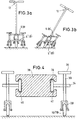
- the training device shown in the figures has according to the exemplary embodiments 1 to 3b two spaced rails 2, 4 made of stainless steel or aluminum, the ends of which are supported by two cross members 6, 8, also made of stainless steel.
- roller-mounted step devices 24, 26 are on the rails 2, 4 attached slidably.
- the bearing can be in the form of a roller bearing, i.e. Roller bearing or ball bearing, or be designed as a simple sliding axial bearing.
- the foot devices have a foot board for receiving a user's foot and optionally a fastening device therefor.
- the kicking device 24 is connected to two rollers 20, 22.
- the kick device 26 is connected with two rollers 16, 18.
- the rollers are used to support the training device on the floor and are movable in the longitudinal direction of the rails 2, 4. Instead of the wheels can also be wheels, for example with pneumatic tires.
- a steering tube 10 is attached vertically.
- Steering tube is a handlebar 12 provided with an upper steering bracket.
- the handlebar has a wheel holder with a at its lower end thereon axle-mounted wheel 14. This serves to support and steer the device.
- a roller is alternatively provided.
- the user stands on the two step devices 24, 26.
- By alternately pushing the feet forward and simultaneously Holding the handlebar 12 can set the exercise device in motion become.
- the use of cross-country shoes can be used provided with cross-country bindings provided on the step facilities be.
- the footboards feature footboards that have foot straps are provided to hold the user's boots or shoes.
- Kick device 24, 26 is connected to a braking device by a Foot of the user is actuated.
- FIG. 4 is an embodiment of the training device according to the invention shown with a one-piece carrier 38 which is on its opposite Side surfaces rail parts 40, 42 has. This is compared to the embodiments of Figures 1 to 3b material saved.
- Rail parts 40, 42 are slides, of which for Simplification, only one carriage 36 is described, which is in the rail part 42 slides.
- the carriage 36 has a plate-shaped sliding device, which with a rod-shaped holder 34 is connected.
- In the holder 34 is a recess provided with which the holder 34 on a rod-shaped or tubular Lanyard 30 slides.
- the connecting means 30 connects the step device 26 with the roll holder for the rolls 16, 18.
- FIG. 6 Preferred, as shown in Fig. 5, is Carriage 36 with its holder 34 on two connecting means 30, 32 without tilting stored.
- the two connecting means 30, 32 are fixed to the one above Kick device 26 connected. Furthermore, they are at their lower end firmly connected to the roll holder 28. Again, at least one role is everyone Provide roller pairs with a backstop to prevent the roller pair from pushing off to allow on the ground. Finally, there is a brake (not shown) provided that allows braking of the kick device.
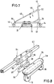
- FIGS. 7 and 8 A further embodiment of the invention is shown in FIGS. 7 and 8.
- a wheel holder 66 is provided, either directly at the rear end of a rail 62 or on a transverse cross member 6 (see Fig. 1) is attached.
- the wheel holder 66 carries a rear wheel 44 which aligned with the front wheel 14. This ensures that a flawless Straight running of the training device according to the invention takes place.
- the wheel 44 is at the same height as wheel 14. It will ensured that the two wheels are attached at such a height that the rollers 16, 18 of the treadmill without significant strain on the rail touch the ground.
- the wheel holder 66 or the Cross member 6 or the rear end of the rail 62 with an arrangement connected by rods 46, 48 which at their other end to the handlebar 12 are connected.
- the arrangement consists of two rod parts 46, 48, which are hinged together to provide a foldable arrangement.
- the Rod part 48 is fastened to the handlebar 12 with a ball bearing 50. Thereby proper steering of the handlebar 12 is ensured.
- the rods 46, 48 on their Fold in the joint.
- the handlebar 12 or the steering tube 10 or the rail 62 is designed to be foldable in order to be able to be folded ensure the entire device.
- the rod parts 46, 48 telescoped into each other.
- FIG. 8 shows a detail of the arrangement from FIG. 7 with the step device 26 shown in detail.
- the kick device 26 is directly on the roll holder 28 attached, and without intermediate parts.
- On the roll holder 28 is in the transverse direction a rod-shaped arm 54 attached, which in a plate-like Holder 56 ends at the end.
- the holder 56 in turn carries two guide rods 58, 58 '.
- These guide rods 58, 58 'slide in slide or roller bearings 60, 60', whereby the sliding or roller bearings 60, 60 'are attached to a carriage 64.
- Carriage 64 slides on the rail 62 Support of the rail 62 by the wheels 14, 44 a horizontal arrangement ensured.
- the height of the horizontal position is chosen so that the guide rods 58, 58 'in their central region from the slide or roller bearings 60, 60 'are performed.
- the guide rods 58, 58 ' move up or down in the bearings while the Carriage 64 inclined according to the position of the curve. This is a complication-free Enables the training device to corner.
- each step can be used only one role can be provided if there is sufficient tilting stability is ensured by the suspension of the step device.
- the rail 62 similar to Figure 4 can also be designed as a double rail with a one-piece carrier be when a one-piece carrier is preferred. In this case the order is 8 combined with the arrangement of Figure 4 and there are On both sides of the central support 38, a carriage 64 is arranged to be longitudinally displaceable.
- the treading devices are 24, 26 not guided in rails. Rather, the roller bearings Stepping devices 24, 26 connected at the end to telescopic devices. Of these, only the telescopic devices are to simplify the illustration described, which are connected to the step device 26.
- a telescopic rod 72 is articulated, which in one Telescopic cylinder 70 is guided.
- a telescopic rod 76 is pivotally articulated, which in a telescopic cylinder 74 is performed.
- the training device shown in FIG. 9 is shown in FIG shown folded state. The joints can be dismantled for this purpose.
- FIG. 11 shows a further embodiment of the training device according to the invention.
- the front part is formed similar to a commercial scooter with a handlebar 78, at the upper end of a handlebar 82 is attached.
- the handlebar 78 is guided in a steering tube 80 and at its other end connected to a fork 84 in which a wheel 86 is mounted.
- a support strut 88 is connected to the end with a hinge for folding of the device is designed.
- the mounting rail 90 is end, i.e. H. at its end opposite the wheel 86 a support device connected in the form of a support bracket 104 with it attached wheel 106 is formed.
- a rail for receiving a slide rod 92 or 108 is provided.
- This Slide rods 92, 108 are in the longitudinal direction to the support rail 90 in the rails movable.
- the slide rods 92 and 108 are in turn slidable with rails Carriage of slides 94 and 110 equipped. That way you can Carriage 94, 110 on the slide rods 92, 108 and this in the rails of the Slide mounting rail 90.
- This allows an extension of the leadership of the Reach car 110 over the end of the mounting rail 90 in the rearward direction. This is to achieve a particularly broad-step cross-country simulation sensible.
- carriages 94, 110 are omitted the slide rods are mounted directly in the rails of the mounting rail 90. This simplifies assembly and manufacture. In addition, to mount the mounting rail in a holder and with a toggle screw to determine the desired length.
- the holding members 96, 98 or 112, 114 are at their other ends on a wheel holder 100 or 116 attached, which carries a wheel 102 or 118 fixed to rest on the ground.
- the holding members 96, 98 and 112, 114 are for attachment to the wheel holder 100 or 116 hinged so that the mounting rail 90 are inclined can and the wheels by pivoting the holding members 96, 98 and 112, 114 raise and lower. In this way, the device is inclined for cornering or to compensate for uneven floors easily possible.
- Each wheel holder 100 or 116 has a braking device (not shown) on.
- a footboard of each wheel holder can be swiveled around the Stored longitudinally. With the running board there is one at a rear end Brake shoe connected to the system when the footboard is inclined one of the wheels 102, 118 arrives. This means that every wheel holder or step device can be used brake by lifting the foot.
- the training device according to the invention is distinguished from the State of the art in that it can be used without binding, no ski poles required and easy braking. Furthermore, there is no Boots must be put on and taken off. Balance problems can arise due to the convenient steering can be avoided. Significantly higher speeds are due to the symmetrical arrangement and consequently symmetrical Movement of the user possible.
Landscapes
- Health & Medical Sciences (AREA)
- General Health & Medical Sciences (AREA)
- Physical Education & Sports Medicine (AREA)
- Life Sciences & Earth Sciences (AREA)
- Biophysics (AREA)
- Orthopedic Medicine & Surgery (AREA)
- Cardiology (AREA)
- Vascular Medicine (AREA)
- Motorcycle And Bicycle Frame (AREA)
Applications Claiming Priority (4)
| Application Number | Priority Date | Filing Date | Title |
|---|---|---|---|
| DE19742626 | 1997-09-26 | ||
| DE19742626 | 1997-09-26 | ||
| DE19748215A DE19748215C1 (de) | 1997-09-26 | 1997-10-28 | Trainingsvorrichtung |
| DE19748215 | 1997-10-28 |
Publications (1)
| Publication Number | Publication Date |
|---|---|
| EP0904812A1 true EP0904812A1 (fr) | 1999-03-31 |
Family
ID=26040354
Family Applications (1)
| Application Number | Title | Priority Date | Filing Date |
|---|---|---|---|
| EP98118153A Withdrawn EP0904812A1 (fr) | 1997-09-26 | 1998-09-24 | Dispositif d' entraínement |
Country Status (3)
| Country | Link |
|---|---|
| EP (1) | EP0904812A1 (fr) |
| AU (1) | AU1026799A (fr) |
| WO (1) | WO1999016516A1 (fr) |
Cited By (1)
| Publication number | Priority date | Publication date | Assignee | Title |
|---|---|---|---|---|
| KR100606176B1 (ko) * | 2003-10-01 | 2006-08-01 | 박경희 | 크랭크요동추진수단 보행식 비클 |
Families Citing this family (1)
| Publication number | Priority date | Publication date | Assignee | Title |
|---|---|---|---|---|
| CN108883326B (zh) * | 2016-02-05 | 2021-04-27 | 陶克健康有限责任公司 | 重量训练滑车 |
Citations (8)
| Publication number | Priority date | Publication date | Assignee | Title |
|---|---|---|---|---|
| US3436088A (en) * | 1967-06-19 | 1969-04-01 | Maurice H Kunselman | Roller skis |
| US3856321A (en) | 1972-10-20 | 1974-12-24 | F Solymosi | Wheeled board toy assembly |
| DE2454976A1 (de) | 1974-11-19 | 1976-05-26 | Haakon Lie | Apparat zum imitierten skilaufen |
| DE2830259A1 (de) * | 1978-07-10 | 1980-01-24 | Artur H Schmitt | Trimm-sportgeraet |
| FR2536665A1 (fr) | 1982-11-30 | 1984-06-01 | Tekron Licensing Bv | Machine d'exercice |
| GB2130900A (en) * | 1982-11-30 | 1984-06-13 | Tekron Licensing Bv | Exercise machine |
| EP0304585A1 (fr) | 1987-08-27 | 1989-03-01 | Valentin Küttenbaum | Appareil sportif |
| US5338273A (en) * | 1993-01-27 | 1994-08-16 | Roadmaster Corporation | Quick change mechanism for synchronous/asynchronous exercise machine |
-
1998
- 1998-09-24 AU AU10267/99A patent/AU1026799A/en not_active Abandoned
- 1998-09-24 EP EP98118153A patent/EP0904812A1/fr not_active Withdrawn
- 1998-09-24 WO PCT/EP1998/006104 patent/WO1999016516A1/fr not_active Ceased
Patent Citations (8)
| Publication number | Priority date | Publication date | Assignee | Title |
|---|---|---|---|---|
| US3436088A (en) * | 1967-06-19 | 1969-04-01 | Maurice H Kunselman | Roller skis |
| US3856321A (en) | 1972-10-20 | 1974-12-24 | F Solymosi | Wheeled board toy assembly |
| DE2454976A1 (de) | 1974-11-19 | 1976-05-26 | Haakon Lie | Apparat zum imitierten skilaufen |
| DE2830259A1 (de) * | 1978-07-10 | 1980-01-24 | Artur H Schmitt | Trimm-sportgeraet |
| FR2536665A1 (fr) | 1982-11-30 | 1984-06-01 | Tekron Licensing Bv | Machine d'exercice |
| GB2130900A (en) * | 1982-11-30 | 1984-06-13 | Tekron Licensing Bv | Exercise machine |
| EP0304585A1 (fr) | 1987-08-27 | 1989-03-01 | Valentin Küttenbaum | Appareil sportif |
| US5338273A (en) * | 1993-01-27 | 1994-08-16 | Roadmaster Corporation | Quick change mechanism for synchronous/asynchronous exercise machine |
Cited By (1)
| Publication number | Priority date | Publication date | Assignee | Title |
|---|---|---|---|---|
| KR100606176B1 (ko) * | 2003-10-01 | 2006-08-01 | 박경희 | 크랭크요동추진수단 보행식 비클 |
Also Published As
| Publication number | Publication date |
|---|---|
| WO1999016516A1 (fr) | 1999-04-08 |
| AU1026799A (en) | 1999-04-23 |
Similar Documents
| Publication | Publication Date | Title |
|---|---|---|
| DE69105113T2 (de) | Skate board für Strassenfahren. | |
| EP0392140B1 (fr) | Patin à roulettes dirigeable | |
| DE2925555A1 (de) | Rollereinrichtung, insbesondere zur fortbewegung von personen | |
| DE3506026C2 (fr) | ||
| DE19748215C1 (de) | Trainingsvorrichtung | |
| DE19541966C2 (de) | Transportable Gehhilfe | |
| EP0904812A1 (fr) | Dispositif d' entraínement | |
| DE102006043558B4 (de) | Rollerähnliches zusammenlegbares Sportgerät "Mini"-Tretroller | |
| EP1704901A1 (fr) | Kickboard | |
| EP2623391A2 (fr) | Appareil de transport pour transporter un sac de golf et au moins une personne | |
| AT409754B (de) | Sportgerät für die fortbewegung im alpinen gelände | |
| EP0628465B1 (fr) | Article de sport | |
| WO2007112723A1 (fr) | véhicule et en particulier appareil de sport ou APPAREIL de sport et de détente | |
| DE2730892A1 (de) | Geh- bzw. lauftrainingsgeraet | |
| DE19515905A1 (de) | Fortbewegungsvorrichtung | |
| DE102020000032A1 (de) | Kopplungsvorrichtung und mobile Geh-Hilfe zum Ankoppeln eines selbstbalancierenden Fahrzeugs | |
| DE69811175T2 (de) | Crosslauf-Übungsgerät | |
| AT501683B1 (de) | Skibobähnliches sportgerät | |
| DE19704390A1 (de) | Trainingsgerät | |
| DE20005375U1 (de) | Laufrad zur körperlichen Ertüchtigung | |
| DE202006014205U1 (de) | Rollerähnliches zusammenlegbares Sportgerät "Mini"-Tretroller | |
| DE8206828U1 (de) | Geraet fuer die benutzung als ski-schlitten" | |
| DE9313704U1 (de) | Sport.- und Spielfahrzeug | |
| DE9316154U1 (de) | Tretrad | |
| DE3704672A1 (de) | Einrichtung als stand- bzw. gehhilfe fuer koerperlich behinderte personen |
Legal Events
| Date | Code | Title | Description |
|---|---|---|---|
| PUAI | Public reference made under article 153(3) epc to a published international application that has entered the european phase |
Free format text: ORIGINAL CODE: 0009012 |
|
| AK | Designated contracting states |
Kind code of ref document: A1 Designated state(s): AT BE CH CY DE DK ES FI FR GB GR IE IT LI LU MC NL PT SE |
|
| AX | Request for extension of the european patent |
Free format text: AL;LT;LV;MK;RO;SI |
|
| AKX | Designation fees paid | ||
| REG | Reference to a national code |
Ref country code: DE Ref legal event code: 8566 |
|
| STAA | Information on the status of an ep patent application or granted ep patent |
Free format text: STATUS: THE APPLICATION IS DEEMED TO BE WITHDRAWN |
|
| 18D | Application deemed to be withdrawn |
Effective date: 19991001 |