EP0905332A1 - Recouvrement pour caniveaux d'écoulement - Google Patents
Recouvrement pour caniveaux d'écoulement Download PDFInfo
- Publication number
- EP0905332A1 EP0905332A1 EP98118400A EP98118400A EP0905332A1 EP 0905332 A1 EP0905332 A1 EP 0905332A1 EP 98118400 A EP98118400 A EP 98118400A EP 98118400 A EP98118400 A EP 98118400A EP 0905332 A1 EP0905332 A1 EP 0905332A1
- Authority
- EP
- European Patent Office
- Prior art keywords
- frame
- sections
- bridge
- cover according
- longitudinal
- Prior art date
- Legal status (The legal status is an assumption and is not a legal conclusion. Google has not performed a legal analysis and makes no representation as to the accuracy of the status listed.)
- Granted
Links
- 239000002184 metal Substances 0.000 claims abstract description 5
- 229910052751 metal Inorganic materials 0.000 claims abstract description 5
- 230000007704 transition Effects 0.000 claims description 7
- 229910000746 Structural steel Inorganic materials 0.000 claims description 6
- 238000004049 embossing Methods 0.000 claims description 3
- 230000006641 stabilisation Effects 0.000 claims 1
- 238000011105 stabilization Methods 0.000 claims 1
- 210000002414 leg Anatomy 0.000 description 15
- 238000004519 manufacturing process Methods 0.000 description 6
- 238000013461 design Methods 0.000 description 3
- 238000005553 drilling Methods 0.000 description 2
- 238000009434 installation Methods 0.000 description 2
- JEIPFZHSYJVQDO-UHFFFAOYSA-N iron(III) oxide Inorganic materials O=[Fe]O[Fe]=O JEIPFZHSYJVQDO-UHFFFAOYSA-N 0.000 description 2
- 210000000689 upper leg Anatomy 0.000 description 2
- 241000755266 Kathetostoma giganteum Species 0.000 description 1
- 229910000831 Steel Inorganic materials 0.000 description 1
- 238000005452 bending Methods 0.000 description 1
- 238000006073 displacement reaction Methods 0.000 description 1
- 238000005246 galvanizing Methods 0.000 description 1
- 238000003197 gene knockdown Methods 0.000 description 1
- 238000003780 insertion Methods 0.000 description 1
- 230000037431 insertion Effects 0.000 description 1
- 239000000463 material Substances 0.000 description 1
- 238000000034 method Methods 0.000 description 1
- 238000012545 processing Methods 0.000 description 1
- 230000000630 rising effect Effects 0.000 description 1
- 229910000679 solder Inorganic materials 0.000 description 1
- 239000010959 steel Substances 0.000 description 1
- 238000003860 storage Methods 0.000 description 1
- 238000012549 training Methods 0.000 description 1
Images


Classifications
-
- E—FIXED CONSTRUCTIONS
- E04—BUILDING
- E04D—ROOF COVERINGS; SKY-LIGHTS; GUTTERS; ROOF-WORKING TOOLS
- E04D13/00—Special arrangements or devices in connection with roof coverings; Protection against birds; Roof drainage ; Sky-lights
- E04D13/04—Roof drainage; Drainage fittings in flat roofs, balconies or the like
- E04D13/0404—Drainage on the roof surface
- E04D13/0445—Drainage channels
-
- E—FIXED CONSTRUCTIONS
- E03—WATER SUPPLY; SEWERAGE
- E03F—SEWERS; CESSPOOLS
- E03F5/00—Sewerage structures
- E03F5/04—Gullies inlets, road sinks, floor drains with or without odour seals or sediment traps
- E03F5/06—Gully gratings
Definitions
- the invention relates to a cover for drainage channels in transition areas between an up-and-coming part of the building and an approximately horizontal, walk-ready, adjacent to a building or trained on it
- Building exterior surface, such as terrace, balcony or the like, with a grate that is housed in a frame is the grille against lateral dislocations encompasses on all sides and a circumferential support for the after has bottom surface area of the grating directed below and each at its two narrow end areas with at least one, preferably two, to the channel bottom
- Directionally adjustable support is provided on their a plate-shaped support surface towards the end wearing.
- a horizontal, walk-in area such as terrace, balcony floor or the like.
- Adjacent areas exposed to weather conditions or arranged in a building to the adjacent high-rise building wall or the like. have a connection, which is 150 mm high. You can see between this surface and a drainage channel in front of the rising wall, then you need a connection height of 50 mm.
- Such troughs are covered with gratings, each are inserted in a frame.
- Medium dimensions Such a channel cover is about 1000 mm long, Width on average 150 mm, for example.
- the frames to be inserted into the gutter are on supports on Gutter floor kept stable in height, to compensate of the irregularities these supports are adjustable in height are held on the frame.
- the supports point relatively wide plate on the bottom, so that at accordingly narrow frame two such supports one each be sufficient in the narrow end area of the frame can.
- these supports must then be used with wide edges Loading of the frame also corresponding tipping resistance exhibit.
- the invention has for its object a cover for Drainage channels of the type mentioned above are available to provide a less visually sensitive appearance offers and, above all, less expensive to manufacture and is mountable.
- the frame consists of two narrow side end sections and optionally one or more in between Longitudinal sections to be arranged in succession is designed to be assembled and that frame bridges are provided between the sections, via which the sections can be connected and the at least in the transition area between longitudinal sections each at least one - preferably two - supports for the load-bearing Have spacing from the channel bottom, the Narrow side end sections with respect to the frame course with inclusion of one of the at least one support the two longitudinal frame spars connecting end bridge and the one or more longitudinal sections to be inserted between them by a
- frame spars connected by a frame bridge are each long-legged U-shaped.
- each channel design in particular, therefore, every gutter length all around continuous frame provided that consists of individual Sections is put together.
- This eliminates in Seen in the longitudinal direction of the channel, transverse frame sections in the coverage area.
- frame bridges are used that fulfill several tasks, namely the connection in the longitudinal direction successively Frame spar sections, their spacing and the inclusion of supports, with only one or two such Supports are provided in this transition area.
- the number of columns per adjoining area of the frame sections to half of those to be provided so far Number of columns.
- the frame sections i.e. both narrow-side end sections and optionally one or more in between longitudinal sections arranged one behind the other are each so trained that seen individually a U-shaped unit with the associated longitudinal frame spars as U-legs and each arranged at one end of this frame spars Bridges that connect these legs together.
- Such a configuration of the individual sections serves easy handling during insertion and alignment inside the drainage channels; the number of to be handled Items are reduced accordingly. At longer channels it is unwieldy, the entire Assemble the frame beforehand and then use it as a unit and align in height.
- the U-shaped Units on the other hand, can be easily inserted into the Insert the gutter and there with regard to the remaining ones manage a few connection points well. Also the delivery or the transport of such U-shaped units saves space.
- U-shaped section units are pre-assembled at the factory. However, it is also possible for the individual parts of these section units on site before inserting into the channel mount, especially if the connection points between the individual parts through easy-to-use connecting means, here in particular to produce hammer rivets are. Such hammer blow rivets, in particular in the case of prefabricated U-shaped units whose Items can be otherwise connected, for example screwed, welded or the like, in the area of Connections to be made after use in the gutter.
- rustproof materials or from rustproof Steel can exist.
- the ones in question here in particular upcoming galvanized angle iron and sheets will be available processed the galvanizing, for example provided with holes.
- the interfaces are protected against rust on site, for example with provided a solder.
- the preferred hammer rivets used can be done without damaging the bore walls insert and knock down.
- the frame can be made from all around running frame bars, i.e. especially angle profiles, be formed, also in the area of the narrow sides, what in Adjacent area to the two adjacent long sides Frame bars for special cuts, for example on Miter leads.
- a second embodiment avoids this in that on the two narrow sides, the all-round lateral grip of the gratings to be used by the two End bridges laterally projecting leg areas are provided are preferably up to the height of the towering legs of the longitudinal frame spars are sufficient or with these in complete a level.
- Such a particularly preferred Execution has the advantage that all longitudinal Frame spars that are regularly of the same length of the sections accordingly uniformly required, identically trained and can also be pre-drilled while the frame bridges with each other and the end bridges also with each other are the same. Except for the height adjustable ones Supports on the bridges, which are identical to each other again, you only need to manufacture the channel cover three differently shaped components.
- Embodiment consist of the frame sections made of galvanized angle iron profiles, whose in the installed position emerging legs surround the gratings on the sides and secure against displacement in the horizontal plane, while the horizontal tavern is the supporting one Form support for the gratings by placing the adjacent ones Reach under the edge areas of the inserted gratings.
- the narrow side end sections are in one embodiment formed from U-shaped frame members and fixed in this form while the ones in between Longitudinal sections of the frame two in frame width spaced apart parallel frame spars have, in one of its end regions to a frame bridge prefabricated connected by these Stand out of the side rails and the inclusion of the freely projecting ends of the frame spars of the next one Longitudinal section or end section of the frame to serve.
- the frame spars are picked up at the place of installation fixed on these bridges.
- the frame bridges are preferred at least transversely to the longitudinal direction of the frame bending stiffening shapes, for example by embossing a sheet from which the frame bridges are formed are provided.
- the frame spars are made from a sheet metal bent into a profile. This also has a grating laterally surrounding the gratings Leg and a support surface for the grates and is from preferably seen from the free end of this support surface while leaving a distance to which the bearing surface forming section in the plane of the emerging leg deformed back. In the range of this distance Use connecting elements similar to the frame bridges. The deformed area can be seen towards the channel bottom bent form a contact surface for a gravel ledge.
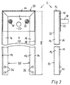
- the narrow-side end section designated overall by 2 in FIG. 1 of the whole, not shown Frame is formed from frame bars 20, which in their Narrow-side end section gripped by an end bridge 22 are.
- the frame spars 20 consist of commercially available galvanized angle iron profiles 12 that form a U-shape End section are assembled, mitred here and welded together if necessary.
- the End bridge 22 can also be welded to the angle iron but preferably riveted joints, in particular those used by hammer rivets. If the end bridge is stable and the involved Basically, frame spars are sufficiently rigid the bars are not welded in the miter area become.
- the vertical legs 14 of the frame spars form the lateral border of gratings, not shown, while the horizontal towards each other Leg 16 the support for the under-gripped edge areas the grate form.
- the end bridge 22 which in the from the inner edges the frame spans the area around two supports 10 carries, which are shown here only with regard to their threaded shafts which are formed on the underside of the end bridge 22, preferably firmly infiltrated with this.
- the frame bridge 8 is like the end bridge 22 with two supports 10 provided, of which in turn only the threaded shafts are shown, but this time at an angle to the longitudinal direction of the frame arranged offset, as can be seen in Figure 1.
- the frame bridge 8 connects the adjacent end sections of consecutive in the longitudinal direction of the frame Frame spars 20 spaced this in terms of Frame width and transfers that to the frame section under consideration applied pressure forces - by walking - on the Support 10 and over this on the channel floor.
- the frame bridge 8 must therefore be correspondingly rigid. This Flexural rigidity is preferably achieved by means not shown Embossing of the sheet forming the frame bridge, the one cause appropriate stiffening of this sheet to the to be able to transmit the aforementioned forces evenly.
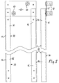
- the longitudinal section 6 of the Framework the one of possibly several intermediate sections between the narrow side end sections 2 and 4 ( Figure 3) consists of two in the width of the frame spaced apart parallel frame spars 20, which at its one end region via a frame bridge 8 are interconnected, in terms of execution, the connection and the tasks equal to those Frame bridge 8, which in connection with Figure 1 above was described.
- the frame bridges 8 are therefore for all frame sections have the same design and are arranged accordingly.
- the frame bridge 8 also has the task of also Ensure that the frame spars 20 run parallel.
- Figure 3 shows the other 4 of the two narrow end portions 2 and 4, except for the frame bridge 8 of the end section 2 with respect to the vertical longitudinal median plane of the Frame is mirror image of the end portion 2 is formed.
- the U-shaped Arrangement of the frame spars and the supports 10 is thus reference is made to the corresponding statements relating to FIG. 1.
- Cover frames can thus be made from the above-mentioned sections of any length, where if necessary, the freely projecting ends of in the longitudinal direction of the frame extending frame spars 20 one Longitudinal section 6 or the end section 4 are shortened, to be adaptable to intermediate lengths. After simple Then only holes 26 are cut off required.
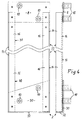
- the second, particularly preferred embodiment according to Figures 4 to 6 one of two narrow-side end sections and - here a - longitudinal section differs with regard to the structure and the longitudinal side used angular profile frame spars and the frame bridges between the sections almost not from the first Embodiment according to Figures 1 to 3, which is why for these parts also have the same reference numbers for both embodiments were chosen.
- the main difference between the two embodiments is the design of the two narrow-sided End regions 2 and 4 in that instead of the narrow side running short angular profile frame spars in the first embodiment now in the second embodiment a leg area 32 occurs as a bend at the narrow edge of the respective end bridge 30 is trained.
- This leg area 32 when running the end bridge made of sheet metal simply from the bridge level vertically bent upwards, takes over the task of the all-round Wrapping around the grating on the two narrow sides. In this way you not only save the individual part of the short narrow-sided frame spars, but you need also no special cut in these end areas of the Longitudinal frame spars, including them where appropriate, that of longitudinal sections all identical and symmetrical about their ends about the transverse median plane are trained. So only from a matching one Workpiece existing frame bars no distinction in the manufacture, handling and processing be, which makes the manufacturing process quite significant simplified and cheaper.
Landscapes
- Engineering & Computer Science (AREA)
- Hydrology & Water Resources (AREA)
- Water Supply & Treatment (AREA)
- Structural Engineering (AREA)
- Health & Medical Sciences (AREA)
- Life Sciences & Earth Sciences (AREA)
- Architecture (AREA)
- Public Health (AREA)
- Civil Engineering (AREA)
- Floor Finish (AREA)
- Supports For Pipes And Cables (AREA)
- Centrifugal Separators (AREA)
- External Artificial Organs (AREA)
- Switch Cases, Indication, And Locking (AREA)
- Sewage (AREA)
Applications Claiming Priority (2)
| Application Number | Priority Date | Filing Date | Title |
|---|---|---|---|
| DE29717376U | 1997-09-29 | ||
| DE29717376 | 1997-09-29 |
Publications (2)
| Publication Number | Publication Date |
|---|---|
| EP0905332A1 true EP0905332A1 (fr) | 1999-03-31 |
| EP0905332B1 EP0905332B1 (fr) | 2003-02-26 |
Family
ID=8046595
Family Applications (1)
| Application Number | Title | Priority Date | Filing Date |
|---|---|---|---|
| EP98118400A Expired - Lifetime EP0905332B1 (fr) | 1997-09-29 | 1998-09-29 | Recouvrement pour caniveaux d'écoulement |
Country Status (3)
| Country | Link |
|---|---|
| EP (1) | EP0905332B1 (fr) |
| AT (1) | ATE233355T1 (fr) |
| DE (2) | DE29817430U1 (fr) |
Cited By (1)
| Publication number | Priority date | Publication date | Assignee | Title |
|---|---|---|---|---|
| DE102004049944A1 (de) * | 2004-10-13 | 2006-04-20 | Dallmer Gmbh & Co. Kg | Ablaufvorrichtung für den Einbau in eine Bodenöffnung |
Families Citing this family (1)
| Publication number | Priority date | Publication date | Assignee | Title |
|---|---|---|---|---|
| DE202019107083U1 (de) * | 2019-12-18 | 2021-03-19 | Schlüter-Systems Kg | Rahmen für einen Bodenablauf |
Citations (3)
| Publication number | Priority date | Publication date | Assignee | Title |
|---|---|---|---|---|
| EP0606606A1 (fr) * | 1993-01-14 | 1994-07-20 | SCHOOP & CO. AG | Rigole de drainage pour toits plats et terrasses |
| EP0687784A1 (fr) * | 1994-06-16 | 1995-12-20 | Aco Severin Ahlmann Gmbh & Co. Kg | Rigole de drainage pour bâtiments |
| DE29607127U1 (de) * | 1996-04-19 | 1997-08-21 | Gutjahr, Walter, 64404 Bickenbach | Höhenverstellbarer Drainagerost |
-
1998
- 1998-09-29 AT AT98118400T patent/ATE233355T1/de not_active IP Right Cessation
- 1998-09-29 DE DE29817430U patent/DE29817430U1/de not_active Expired - Lifetime
- 1998-09-29 EP EP98118400A patent/EP0905332B1/fr not_active Expired - Lifetime
- 1998-09-29 DE DE59807294T patent/DE59807294D1/de not_active Expired - Lifetime
Patent Citations (3)
| Publication number | Priority date | Publication date | Assignee | Title |
|---|---|---|---|---|
| EP0606606A1 (fr) * | 1993-01-14 | 1994-07-20 | SCHOOP & CO. AG | Rigole de drainage pour toits plats et terrasses |
| EP0687784A1 (fr) * | 1994-06-16 | 1995-12-20 | Aco Severin Ahlmann Gmbh & Co. Kg | Rigole de drainage pour bâtiments |
| DE29607127U1 (de) * | 1996-04-19 | 1997-08-21 | Gutjahr, Walter, 64404 Bickenbach | Höhenverstellbarer Drainagerost |
Cited By (2)
| Publication number | Priority date | Publication date | Assignee | Title |
|---|---|---|---|---|
| DE102004049944A1 (de) * | 2004-10-13 | 2006-04-20 | Dallmer Gmbh & Co. Kg | Ablaufvorrichtung für den Einbau in eine Bodenöffnung |
| DE102004049944B4 (de) * | 2004-10-13 | 2015-04-02 | Dallmer Gmbh & Co. Kg | Ablaufvorrichtung für den Einbau in eine Bodenöffnung |
Also Published As
| Publication number | Publication date |
|---|---|
| DE29817430U1 (de) | 2000-02-17 |
| ATE233355T1 (de) | 2003-03-15 |
| DE59807294D1 (de) | 2003-04-03 |
| EP0905332B1 (fr) | 2003-02-26 |
Similar Documents
| Publication | Publication Date | Title |
|---|---|---|
| EP2354368A2 (fr) | Etrier de fixation pour isolations murales | |
| DE3702657A1 (de) | Gewaechshaus oder dergleichen mit geteilten, fuer gekruemmte abschnitte geeigneten verglasungsstaeben, sowie verfahren zu dessen herstellung | |
| DE3346171C2 (de) | Als Leichtbauprofil ausgebildete Profilleiste, insbesondere Deckentrageprofil | |
| EP0212228A2 (fr) | Dispositif pour l'ancrage de plaques | |
| DE19601065A1 (de) | Skelettgebäude aus Profilstäben | |
| EP0802287A2 (fr) | Grille de drainage réglable en hauteur | |
| EP2172601B1 (fr) | Escalier librement suspendu | |
| DE10153914B4 (de) | Quaderförmiger Baustein, ein Mauerwerk aus Bausteinen und Verwendungen des Mauerwerks | |
| EP1457618A1 (fr) | Grille | |
| EP0905332B1 (fr) | Recouvrement pour caniveaux d'écoulement | |
| DE29807808U1 (de) | Unterkonstruktion zur Halterung von Fassadenelementen | |
| DE9411477U1 (de) | Rinne zum Verlegen in einem Fußboden | |
| DE69329979T2 (de) | System zum befestigen von plattenförmigen elementen an einer oberfläche | |
| EP0324169A1 (fr) | Bloc d'installation | |
| DE2117499A1 (de) | Regalanlage | |
| CH630986A5 (de) | Sturz fuer durchgaenge, tuer- und fensteroeffnungen. | |
| EP3296475B1 (fr) | Balcon et procédé de fabrication d'un tel balcon | |
| DE202006011801U1 (de) | Rahmenkonstruktion für die Montage eines Sanitärgegenstandes | |
| CH635890A5 (en) | Partition-wall structure for forming boarded-off areas, principally for separating off cellars | |
| EP1138840A2 (fr) | Goulotte d'écoulement | |
| EP1435416A1 (fr) | Caniveau d'écoulement et méthode de production d'un tel caniveau d'écoulement | |
| EP2425069B1 (fr) | Dispositif d'aide à la mise à niveau pour des supports en bois/en poutre, notamment de recouvrements de balcon et de terrasse | |
| DE19629108B4 (de) | Verkleidung | |
| DE202006009323U1 (de) | Tragkörper für ein Geländer mit einer scheibenförmigen Füllung | |
| DE19943525A1 (de) | Befestigungsvorrichtung für Glas-Fassadenbekleidungen |
Legal Events
| Date | Code | Title | Description |
|---|---|---|---|
| PUAI | Public reference made under article 153(3) epc to a published international application that has entered the european phase |
Free format text: ORIGINAL CODE: 0009012 |
|
| AK | Designated contracting states |
Kind code of ref document: A1 Designated state(s): AT DE FR GB |
|
| AX | Request for extension of the european patent |
Free format text: AL;LT;LV;MK;RO;SI |
|
| 17P | Request for examination filed |
Effective date: 19990831 |
|
| AKX | Designation fees paid |
Free format text: AT DE FR GB |
|
| GRAG | Despatch of communication of intention to grant |
Free format text: ORIGINAL CODE: EPIDOS AGRA |
|
| GRAG | Despatch of communication of intention to grant |
Free format text: ORIGINAL CODE: EPIDOS AGRA |
|
| GRAH | Despatch of communication of intention to grant a patent |
Free format text: ORIGINAL CODE: EPIDOS IGRA |
|
| 17Q | First examination report despatched |
Effective date: 20020619 |
|
| GRAH | Despatch of communication of intention to grant a patent |
Free format text: ORIGINAL CODE: EPIDOS IGRA |
|
| GRAA | (expected) grant |
Free format text: ORIGINAL CODE: 0009210 |
|
| AK | Designated contracting states |
Designated state(s): AT DE FR GB |
|
| REG | Reference to a national code |
Ref country code: GB Ref legal event code: FG4D Free format text: NOT ENGLISH |
|
| REF | Corresponds to: |
Ref document number: 59807294 Country of ref document: DE Date of ref document: 20030403 Kind code of ref document: P |
|
| GBT | Gb: translation of ep patent filed (gb section 77(6)(a)/1977) | ||
| ET | Fr: translation filed | ||
| PLBE | No opposition filed within time limit |
Free format text: ORIGINAL CODE: 0009261 |
|
| STAA | Information on the status of an ep patent application or granted ep patent |
Free format text: STATUS: NO OPPOSITION FILED WITHIN TIME LIMIT |
|
| 26N | No opposition filed |
Effective date: 20031127 |
|
| PGFP | Annual fee paid to national office [announced via postgrant information from national office to epo] |
Ref country code: AT Payment date: 20070930 Year of fee payment: 10 |
|
| PGFP | Annual fee paid to national office [announced via postgrant information from national office to epo] |
Ref country code: GB Payment date: 20070920 Year of fee payment: 10 |
|
| PGFP | Annual fee paid to national office [announced via postgrant information from national office to epo] |
Ref country code: FR Payment date: 20070927 Year of fee payment: 10 |
|
| GBPC | Gb: european patent ceased through non-payment of renewal fee |
Effective date: 20080929 |
|
| REG | Reference to a national code |
Ref country code: FR Ref legal event code: ST Effective date: 20090529 |
|
| PG25 | Lapsed in a contracting state [announced via postgrant information from national office to epo] |
Ref country code: AT Free format text: LAPSE BECAUSE OF NON-PAYMENT OF DUE FEES Effective date: 20080929 |
|
| PG25 | Lapsed in a contracting state [announced via postgrant information from national office to epo] |
Ref country code: FR Free format text: LAPSE BECAUSE OF NON-PAYMENT OF DUE FEES Effective date: 20080930 |
|
| PG25 | Lapsed in a contracting state [announced via postgrant information from national office to epo] |
Ref country code: GB Free format text: LAPSE BECAUSE OF NON-PAYMENT OF DUE FEES Effective date: 20080929 |
|
| REG | Reference to a national code |
Ref country code: DE Ref legal event code: R082 Ref document number: 59807294 Country of ref document: DE Representative=s name: KASTEL PATENTANWAELTE PARTG MBB, DE Ref country code: DE Ref legal event code: R082 Ref document number: 59807294 Country of ref document: DE Representative=s name: KASTEL PATENTANWAELTE, DE |
|
| PGFP | Annual fee paid to national office [announced via postgrant information from national office to epo] |
Ref country code: DE Payment date: 20171123 Year of fee payment: 20 |
|
| REG | Reference to a national code |
Ref country code: DE Ref legal event code: R071 Ref document number: 59807294 Country of ref document: DE |