EP3296475B1 - Balcon et procédé de fabrication d'un tel balcon - Google Patents
Balcon et procédé de fabrication d'un tel balcon Download PDFInfo
- Publication number
- EP3296475B1 EP3296475B1 EP17191931.9A EP17191931A EP3296475B1 EP 3296475 B1 EP3296475 B1 EP 3296475B1 EP 17191931 A EP17191931 A EP 17191931A EP 3296475 B1 EP3296475 B1 EP 3296475B1
- Authority
- EP
- European Patent Office
- Prior art keywords
- leg
- balcony
- cassette
- coupling
- base
- Prior art date
- Legal status (The legal status is an assumption and is not a legal conclusion. Google has not performed a legal analysis and makes no representation as to the accuracy of the status listed.)
- Active
Links
Images


Classifications
-
- E—FIXED CONSTRUCTIONS
- E04—BUILDING
- E04B—GENERAL BUILDING CONSTRUCTIONS; WALLS, e.g. PARTITIONS; ROOFS; FLOORS; CEILINGS; INSULATION OR OTHER PROTECTION OF BUILDINGS
- E04B1/00—Constructions in general; Structures which are not restricted either to walls, e.g. partitions, or floors or ceilings or roofs
- E04B1/003—Balconies; Decks
-
- E—FIXED CONSTRUCTIONS
- E04—BUILDING
- E04D—ROOF COVERINGS; SKY-LIGHTS; GUTTERS; ROOF-WORKING TOOLS
- E04D11/00—Roof covering, as far as not restricted to features covered by only one of groups E04D1/00 - E04D9/00; Roof covering in ways not provided for by groups E04D1/00 - E04D9/00, e.g. built-up roofs, elevated load-supporting roof coverings
- E04D11/005—Supports for elevated load-supporting roof coverings
-
- E—FIXED CONSTRUCTIONS
- E04—BUILDING
- E04D—ROOF COVERINGS; SKY-LIGHTS; GUTTERS; ROOF-WORKING TOOLS
- E04D13/00—Special arrangements or devices in connection with roof coverings; Protection against birds; Roof drainage ; Sky-lights
- E04D13/04—Roof drainage; Drainage fittings in flat roofs, balconies or the like
- E04D13/0404—Drainage on the roof surface
- E04D13/0477—Underroof drainage layers
Definitions
- the invention relates to a balcony for attachment to a building wall with the features of claim 1.
- the invention further relates to a method for producing such a balcony with the features of claim 8.
- a balcony is a platform on a building that is above ground level and protrudes from the building. It is usually surrounded by a parapet or a railing.
- each cassette element is shaped perpendicular to the direction of extension in such a way that it has a base that forms part of the underside of the balcony floor and that, starting from the base, at least one coupling leg with a coupling area spaced from the base for connecting adjacent cassette elements and / or for support of a balcony floor covering extends to the balcony floor structure.
- Each coupling area has a form-fitting section, which extends along the direction of extension and via which adjacent cassette elements are connected to one another in a form-fitting manner.
- a balcony for attachment to a house wall which has cassette elements.
- the base of the cassette element forms part of the underside of the balcony floor, at least one coupling leg extending from the base with a coupling region spaced apart from the base.
- This coupling area of the coupling leg is designed such that adjacent cassette elements are connected to one another and / or form a support for a balcony floor covering.
- the connection between the two cassette elements is made by a form fit of each of its coupling legs with the associated form fit area on a strut.
- cassette elements are described, each of which has a form-fitting section, via which adjacent cassette elements are connected to one another by means of a strut.
- the object is achieved by a balcony with the features of claim 1 and by a method for producing such a balcony with the features of claim 8.
- the cassette elements, the carrier profile or both are made of folded thin sheet.
- a coupling leg angle A of 60 to 70 degrees is formed in each case between the base and coupling leg of the cassette elements, the form-fitting section of each coupling leg having a first form-fitting section extending parallel to the base of the cassette element and then a second form-fitting section being formed on the first form-fitting section which extends angled or curved away from the first form-fitting section.
- a thin sheet consists of a metal or a metal alloy, preferably of galvanized steel.
- the thickness of the thin sheet is preferably up to 3 millimeters, particularly preferably up to 2.5 millimeters and most preferably 1 to 2 millimeters.
- Such a thin sheet can be machined well using a forming tool, in particular a folding tool.
- the cassette elements made of thin sheet are significantly lighter than flat steel with material thicknesses well over 5 mm and the cassette elements made of thin sheet metal by folding are significantly cheaper than extruded aluminum profiles. This makes these cassette elements cheaper and easier to transport and assemble. Regular transport and assembly of the entire balcony can therefore be carried out by a single person without special lifting tools.
- the use of thin sheet metal is also very advantageous for forming the support profile. This means that a lifting crane for moving support profiles / support profile frames can usually be dispensed with. This further reduces the effort for transport and assembly and thus the total costs.
- a uniform design along the direction of extension of the coupling leg of the cassette element is inevitably achieved if the cassette element is produced by folding a thin metal sheet. Through the manufacturing step of the folding, the direction of extension of the cassette element is inevitably predetermined by the edge of the folding tool.
- folding used in the context of this invention is a bending process known from the forming technology.
- the term folding is preferably used below.
- Bending is a long-known and established forming process, usually for sufficiently thin sheets of metal or metal alloys. This process is easy to control and opens up a wide variety of possible coupling legs. Folding can usually be done at high speed. Depending on the precision of the forming tool, the processing results can be reliably reproduced down to the millimeter range. As a result, this forming technique is very well suited for the efficient production of cassette elements with coupling legs designed in this way.
- the aforementioned method enables a wide variety of geometries of the cassette elements. This in turn makes it possible, for example, to prefabricate balcony components in large quantities. This reduces both the production costs and the assembly time for a balcony.
- a cassette element formed in one piece preferably extends from two opposing balcony floor supports, which are structurally formed in opposite support profile frame sections, along the direction of extension already mentioned.
- the base of a cassette element has a width of preferably 10 to 100 centimeters, particularly preferably 15 to 70 centimeters and most preferably 20 to 30 centimeters, perpendicular to the direction of extension, especially when using thin sheet metal.
- Each cassette element has at least one coupling leg. This is preferably arranged in the edge region of the base. However, there can also be a plurality of coupling legs per cassette element, in particular two, which extend along the direction of extension at both edge regions of the base of the cassette element.
- a cassette element can have a coupling leg and a further leg which extends away from the base and has no function for coupling adjacent cassette elements.
- This further leg can be designed as a starting leg or as a closing leg, which extends at a defined angle, for example essentially perpendicularly, or curved with a varying angle from the base of the cassette elements.
- the further leg forms both a structural reinforcement for supporting the cassette element on the balcony floor support of the carrier profile frame and a lateral limitation of the base in order to give it a tub function for guiding water that reaches the cassette elements from above.
- Each coupling leg has a coupling area with a form-fitting section for coupling adjacent cassette elements.
- Two such adjacent cassette elements are mechanically coupled to one another by means of the interlocking sections of their coupling regions that extend parallel along the direction of extension.
- the form-fitting sections are designed in such a way that a displacement of adjacent cassette elements transversely to the direction of extension is blocked. In order to prevent a relative displacement of adjacent cassette elements along the direction of extension, the use of fewer fixing means that block such a displacement is sufficient. This also reduces the assembly effort.
- the balcony floor structure formed from the cassette elements also fulfills the function of drainage in addition to the static requirements.
- the water that hits the top of the balcony floor comes towards the base of each cassette element, which together with the legs extending from the base, in particular the coupling legs, forms a drainage trough, and can be removed from there, for example, by a minimally provided during installation Guide the slope towards a support profile of the support profile frame.
- the carrier profiles, into which the water guided from the cassette elements reaches, are preferably structurally designed such that they have a water drainage section.
- the water can be introduced into a building drainage system that is usually present by means of a drainage device, for example in the form of pipes or channels.
- a drainage device for example in the form of pipes or channels.
- the water can also be conducted into a collecting container, for example from the support profile frame or from the base of a cassette element.
- the floor covering is often not completely in balance in order to cause rainwater to run off in a direction specified by the slope.
- these drainage solutions often provide additional drainage devices, for example complex collecting and pipe systems.
- the balcony ceiling is the visible, unclad part of the underside of the balcony floor that a viewer sees when looking at the balcony above from below.
- the cassette elements which can form a large part of the underside of the balcony floor by means of their respective bases, can be designed in different colors or uniformly. This allows a balcony ceiling to be freely designed with regard to its appearance. For example, if the balcony ceiling is designed in white, the balcony below will receive more light thanks to the increased light reflection.
- the dimensioning of the cassette elements, in particular transverse to their direction of extension also contributes to the optically structured appearance of the balcony ceiling. As a result, further measures, such as an additionally provided cladding, for designing the balcony ceiling can be dispensed with. This can save time and money in designing the balcony ceiling.
- the coupling leg can be designed as an overlapping leg or as an engaging leg.
- Each version of the coupling leg has a form-fitting section. Viewed from the base of the cassette element, the form-fitting section is arranged on the upper side of the engaging leg and on the underside of the overlapping leg. If an overlapping leg and an engaging leg are coupled to one another for connecting two cassette elements, the overlapping leg extends over the engaging leg. As a result, the form-fitting sections touch on the underside of the overlapping leg and the top of the engaging leg. If a weight acts from the base of the cassette element, viewed from above, on the overlapping leg, the form fit between the overlapping leg and the engaging leg is loaded by the weight. On Objects and / or people located on the balcony generate such weight forces.
- a balcony floor support structure is formed from adjacent cassette elements, which supports loads borne by a balcony floor covering usually arranged thereon.
- a plurality of cassette elements each have a coupling leg at both ends of the base, one coupling leg being designed as an overlapping leg and the other coupling leg being designed as an engaging leg, and the positive connection at the form-fitting sections of adjacent cassette elements through the Coupling the overlapping leg of a first cassette element with the engaging leg of a second cassette element is made.
- the majority of the cassette elements have an overlapping leg and an engaging leg for each cassette element. As a result, several adjacent cassette elements can be positively connected to one another. This is preferably used to form a coherent balcony floor structure made up of significantly more than two cassette elements. Due to this connectivity of the cassette elements, the individual cassette elements can be relatively small compared to the total area of the balcony floor construction. This facilitates the transport of the balcony components and the assembly of the balcony.
- the embodiments with a cassette element having an overlapping leg are advantageously characterized in that a section of the overlapping leg running parallel to the base of the cassette element forms with its upper side a floor covering for a balcony floor covering.
- the size of the bearing surface of this For a given height of the cassette element, the floor covering of the cassette element is determined, inter alia, by the coupling leg angle.
- the width of the floor covering support of the cassette element and its spacing from the base is selected.
- the floor covering of the cassette element can be covered with a balcony floor covering, for example made of wood, plastic, concrete, stone, other materials or a combination thereof. These materials can for example be screwed to the floor covering of the cassette element. This connection and / or the weight of the balcony floor covering exerts an additional holding force on the positive locking of the positive locking sections.
- the cassette elements could, for example, be folded from thin sheet metal such that the floor covering support of the cassette element extends at a distance from the base and extends perpendicularly to the direction of extension, as viewed continuously. As a result, the top of the cassette elements forms the top of the balcony floor.
- All of the preceding configurations are preferably characterized in that adjacent cassette elements are fastened to one another in their common positive-locking sections with fixing means.
- the following are suitable as fixatives: adhesive, screws, nails, rivets, soldering, welding, other fixatives not mentioned here, or combinations thereof.
- the adjacent cassette elements are preferably riveted together. For this purpose, after the cassette elements have been positioned at defined points in their interlocking sections, the holes are first drilled, followed by riveting these holes.
- the Fastening adjacent cassette elements fixes the previously established positions of adjacent cassette elements to one another and prevents their displacement along or transversely to the direction of extension of the cassette elements.
- the cassette elements fixed to each other form the balcony floor structure, which is preferably made solely from thin sheet metal and which, despite the low material thickness, provides the resilience required for building balconies via the riveted, partially form-fitting sheet metal connection. If all adjacent cassette elements are connected to one another by means of fixing means, individual cassette elements can neither be removed nor displaced.
- a balcony floor structure formed with such a balcony floor structure is stable and very light.
- the use of rivets has the advantage that rivets can be drilled out. As a result, cassette elements which have been fixed to one another can subsequently be disassembled if this is necessary, for example, for a repair replacement of an individual cassette element.
- the coupling leg angles can be of different sizes.
- the embodiment described above with the coupling leg angle is preferably characterized in that the coupling leg angles of each cassette element are of the same size.
- each coupling leg has a first interlocking section that extends parallel to the base of the cassette element.
- This first form-fitting section is through the in the coupling leg angle extending away from the base coupling leg spaced from the base and oriented parallel to the base.
- the first form-fitting section is directed upwards, that is to say directed away from the base and oriented parallel to the base.
- the first positive-locking section of a coupling arm designed as an overlapping leg which is opposite this first positive-locking section of the engaging leg, is in turn oriented downwards, ie towards the base, and also aligned parallel to the base.
- the back of the overlapping leg is also oriented parallel to the base with the same coupling leg material thickness and points upwards when viewed from the base.
- This section at least partially forms a fixing agent section. This fixing means section is accessible from above.
- adjacent cassette elements can be very easily attached to one another from above by means of fixing means after they have been connected to one another by means of the form-fitting sections of adjacent overlapping legs and engaging legs.
- This attachment is preferably carried out by means of rivets.
- other fixing agents can also be used for this, for example screws.
- Using the fixing means in this way has the advantage, among other things, that each cassette element can still be displaced along the direction of extension before the fastening of adjacent cassette elements.
- a cassette element is only attached to the adjacent cassette element when it has reached its intended position. This facilitates the step-by-step installation of the balcony floor structure.
- a second positive-locking section is formed which extends away from the first positive-locking section in an angled or curved manner.
- the engaging leg of a cassette element hooks under the overlapping leg of another adjacent cassette element and the combination of the first form-fitting section and the second form-fitting section forms an edge or a curvature.
- this edge or curvature acts in the form-fitting section as a mechanical stop which limits the movement of adjacent cassette elements transversely to the direction of extension.
- This mechanical stop facilitates the step-by-step assembly of adjacent cassette elements in that the overlapping leg is first applied with its second form-fitting section at an acute angle to the second form-fitting section of the engaging leg. Subsequently, this acute angle is reduced to zero by rotating the cassette element with the overlapping leg about an axis of rotation parallel to the direction of extension, thereby producing the positive locking of the form-fitting sections of the adjacent cassette elements.
- the second form-fitting section preferably extends at a right angle from the first form-fitting section. This represents a variant of the angled form-fitting section that is particularly easy to produce, particularly by folding thin sheet metal.
- the support profile frame encloses the balcony floor construction and the cassette elements extend in one piece along their direction of extension between opposite sections of the support profile frame. Since the cassette elements extend in one piece along their direction of extension between opposite sections of the carrier profile frame, no further support elements for the cassette elements along their direction of extension are required. This reduces the effort for the balcony assembly. Furthermore, the cassette elements, which extend in one piece, also serve as an aesthetic design element for the balcony design. This allows for elaborate subsequent design measures on the balcony, for example in the form of Disguises are dispensed with. This reduces the time, material and costs for the balcony design.
- Enclosing the balcony floor construction by the support profile frame also has the consequence that rainwater hitting the balcony from above is transported in the direction of the support profile frame and can be drained from there, for example by means of a piping system.
- This line system is preferably formed from water drainage sections, which is designed as a structural component of the support profiles forming the support profile frame. In this way, it is not necessary to provide components that serve only to drain the balcony floor construction of the balcony.
- the balcony floor structure integrates the drainage functionality with its structural function, so to speak.
- the object on which the invention is based is further achieved by a method for producing a balcony with the features of claim 8.
- the folding claimed in the context of this invention is a bending process known from the forming technology. In the following, only the term beveling is used.
- the carrier profiles forming the carrier profile frame consist of metal, a metal alloy, plastic or a combination of the aforementioned materials.
- the carrier profile frame is formed by joining the carrier profiles to form a carrier profile frame and then connecting them to one another. This connection is permanent or detachable. A permanent connection of the carrier profiles to a carrier profile frame is preferred, for example by welding or soldering.
- Such support profiles are preferably designed as follows. Viewed in cross section, such a carrier profile is shaped like a square C with an opening. An upper end portion extends from the upper end of this opening, while a lower end portion extends from the lower end of the opening. These two end sections extend essentially perpendicularly away from the carrier profile and are aligned parallel to one another. The lower end section forms a balcony floor covering of the support profile, while the upper end section forms a floor covering support of the support profile for a balcony floor covering, which is regularly provided as part of the balcony floor construction.
- the support profile frame is attached to a building wall using a holding system.
- This holding system is designed with or without a vertical stand system. Without a stand system, the load is taken up by means of one or more cantilever beams and possibly by additional cables, preferably made of metal, connected to the building wall or neighboring balconies.
- the design and mode of operation of a cantilever is described at the beginning.
- the use of a stand system may be necessary for large balconies. In these cases, the stand system provides for a partial or full absorption of the balcony load.
- the cassette elements are made of metal in the form of thin sheet metal.
- a galvanized steel sheet is preferably formed as follows: the thin sheet is folded into a cassette element in a forming tool. The direction of extent of the shaping edge of the shaping tool thereby defines the direction of extent of the cassette element.
- the cassette element has the following structure: viewed in cross section to its direction of extension, the cassette element has a base. After installation, the base is part of the underside of a balcony floor. Assembled cassette elements form the complete underside of the balcony floor with their respective bases. All or part of the underside of the balcony floor can form a balcony ceiling.
- the balcony ceiling is the visible, unclad part of the underside of the balcony floor that a viewer sees when looking at the balcony above from below.
- the thin sheet is folded in such a way that at least one coupling leg extends away from the base along the direction of extension.
- a coupling leg angle is formed between the base and the coupling leg.
- the coupling leg angle is 60 to 70 degrees.
- the coupling leg has a coupling area.
- the coupling area is arranged at a defined distance from the base.
- the coupling region is preferably arranged at the end of the coupling leg facing away from the base.
- the coupling area of the coupling leg is in turn by the folding process of the sheet preferably formed at least in sections parallel to the base.
- the coupling area has a form-fitting section.
- the form-fitting section preferably has a first and a second form-fitting section adjacent thereto.
- first form-fitting section is formed parallel to the base as part of the coupling area.
- second form-fitting section is angled or curved in the direction of the base.
- the second form-fitting section preferably forms the end of the coupling area.
- Such coupling legs are designed as so-called engagement legs or as overlapping legs.
- the first and second form-fitting sections of the engagement leg are each formed on the upper side of the coupling leg facing away from the base.
- first and second form-fitting section of the overlapping leg is arranged on the underside of the coupling leg facing the base.
- the cassette element When viewed in cross section, the cassette element preferably has a coupling leg designed as an overlapping leg at one end of the base and a coupling leg designed at the other end of the base.
- individual cassette elements can be provided, which are bent at the edge of the mutually coupled cassette elements in each case only with a coupling leg designed as an engagement leg or only with a coupling leg designed as an overlapping leg.
- Adjacent cassette elements are connected to one another by means of their adjacent form-fitting sections during the assembly of the balcony floor construction.
- the back of the first form-fitting section of the overlapping leg preferably forms a floor covering support of the cassette element and can therefore be used for laying on a balcony floor covering which forms the visible top of the balcony floor.
- a first folded cassette element of this type is inserted into the support profile frame so that it is on opposite sections of the balcony floor support of the Carrier profile frame rests. These sections are preferably oriented parallel to one another. However, this depends on the geometry of the balcony.
- a second cassette element is then placed on the balcony floor support of the support profile frame.
- the first cassette element is then preferably connected to the adjacent second cassette element as follows.
- the engaging leg of a cassette element hooks under the overlapping leg of another adjacent cassette element and the combination of the first form-fitting section and the second form-fitting section forms an edge or a curvature.
- this edge or curvature acts in the form-fitting section as a mechanical stop which limits the movement of adjacent cassette elements transversely to the direction of extension.
- This mechanical stop facilitates the step-by-step assembly of adjacent cassette elements in that the overlapping leg is first applied with its second form-fitting section at an acute angle to the second form-fitting section of the engaging leg. Subsequently, this acute angle is reduced to zero by rotating the cassette element with the overlapping leg about an axis of rotation parallel to the direction of extension, thereby producing the positive locking of the form-fitting sections of the adjacent cassette elements.
- cassette elements are preferably inserted into the carrier profile frame and connected to one another until the surface enclosed by the carrier profile frame is completely filled.
- the cassette elements can be displaced along the direction of extension up to a certain point so that they can be threaded into the carrier profile frame.
- the cassette elements which are positively connected to one another, are then fixed to one another on the carrier profile frame. Screws, rivets, adhesives, other fixing agents or a combination thereof are used for this fixing. Rivets are preferably used for this.
- a hole is made in the form-fitting area of the cassette element through the thin sheet of both cassette elements.
- the rivet is placed in this hole and the two cassette elements are riveted together in this way.
- a corresponding procedure is carried out for fixing the cassette elements to the carrier profile frame.
- the use of rivets has the advantage that rivets can be drilled out. This means that cassette elements that are fixed together can be subsequently dismantled if this is necessary.
- a balcony floor covering is placed on the floor covering support of the support profile and the floor covering supports of the adjacent cassette elements and fixed to the cassette elements. Screws, nails or specially designed fixing agents are suitable for this. Screws are preferably used for this.
- the advantage of this process is that many balcony components can be prefabricated, the transport of the balcony components is therefore easy and the final assembly to a balcony can be carried out by a few people without special lifting equipment.
- the preceding method is preferably developed in such a way that the carrier profiles forming the carrier profile frame are also bent from thin sheet metal, a carrier profile strand being bent from thin sheet first, then a plurality of carrier profiles are mitred from the carrier profile strand and the majority of carrier profiles become a carrier profile frame connected.
- the carrier profiles are preferably cut directly from the carrier profile strand to the required length by means of a miter cut, or they are First cut to the required length and then the carrier profile is mitred.
- the thin sheet used in the folding is made of a metal or a metal alloy, preferably steel.
- the thickness of the thin sheet is preferably up to 3 millimeters, particularly preferably up to 2.5 millimeters and most preferably 1 to 2 millimeters.
- beveled thin sheet metal for support profile frames leads to a significant weight saving in comparison to many currently used support profile frames made of thicker flat steel.
- the flat steel used regularly has two to three times the material thickness, so that the components made from it have double and triple the weight. In comparison, the significantly lower weight of the has less effort in transport and assembly and thus also lower costs.
- MSG welding is preferably used.
- MSG welding is understood to mean metal welding with inert gases. This is a welding process that uses protective gas. This shielding gas prevents the weld from oxidizing after welding. Argon, helium or other suitable protective gases are used as protective gases. This welding process is established and is well mastered.
- the advantage is that, in particular, the weld seams of cut galvanized steel sheets no longer have to be reworked after welding, for example using mechanical methods and / or rust inhibitors.
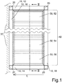
- FIG. 1 shows a preferred embodiment of a balcony in a schematic plan view, not to scale, of the balcony.
- the balcony has a support profile frame 10 with two long and two short sides, which is rectangular in plan view.
- the support profile frame 10 is formed from a first support profile 12, a second support profile 14, a third support profile 16 and a fourth support profile 18.
- the support profiles 16 and 18 form the long sides of the support profile frame 10, which is rectangular in plan view.
- the short sides of the support profile frame 10, which is rectangular in plan view are formed by the support profiles 12 and 14.
- a direction of extension E extends between the carrier profiles 16 and 18.
- the direction of extension E is parallel to the carrier profiles 12 and 14.
- the carrier profile frame 10 is connected to four vertical stands 20.
- the four stands 20 are arranged at the four corners of the rectangle and serve to accommodate the loads picked up by the balcony. Furthermore, the support profile frame 10 is connected to a building wall 30 by means of a holding system, not shown in this figure.
- the Carrier profile frame 10 encloses a balcony floor support structure 42.
- the balcony floor support structure 42 has a plurality of interconnected cassette elements 50.
- Each cassette element 50 has a rectangular base with two long sides and two short sides. Along the long sides of a cassette element 50 there are one or two connecting sections, not shown here, in which adjacent cassette elements partially overlap. These connecting sections contain support sections and form-fitting sections.
- Each cassette element 50 extends in one piece with the long sides along the direction of extension E between the two carrier profiles 16 and 18.
- the long sides of the cassette elements 50 are thereby parallel to the short carrier profiles 12 and 14.
- the individual cassette elements 50 are positively connected to one another by means of form-fitting sections. These support sections and form-fitting sections are described in detail in the further figures.
- the plurality of cassette elements 50 are composed of an initial cassette element 52, a plurality of central cassette elements 54 and a final cassette element 56.
- the structure of the carrier profile frame 10 and a cassette element 50 is shown in the further figures.
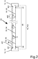
- FIG. 2 shows a cross-sectional view along the dash-dotted line II-II Figure 1 .
- the parts of the carrier profile frame 10 shown here include the first carrier profile 12 and the second carrier profile 14 lying opposite it.
- each of the aforementioned carrier profiles is essentially shaped like a rectangular C with two long vertical sides, two short horizontal sides and an opening for receiving cassette elements 50. This opening is located on one of these two long sides and is arranged above the center of the carrier profile.
- a horizontal upper end portion extends from the upper end of this opening and a horizontal lower end portion extends from the lower end of the opening.
- These two end sections extend essentially perpendicularly away from the carrier profile and are aligned parallel to one another.
- the lower end section forms one Balcony floor support 44 while the upper end portion forms a floor covering support 461 of the support profile frame.
- the balcony floor support structure 42 forms a balcony floor construction 40 together with a balcony floor covering 46.
- the balcony floor covering 46 usually consists of wooden planks or stone slabs which are placed on the floor covering support 461 of the support profile and / or the floor covering support 462 of the cassette element.
- the wooden planks or stone slabs regularly extend in one piece along the direction of extension E and can be fixed to the floor covering support 461 of the carrier profile and / or the floor covering support 462 of the cassette element by means of screws, not shown here.
- the balcony floor construction 40 has a balcony floor top 401 and a balcony floor bottom 402.
- the top of the balcony floor 401 is formed from the top of the balcony floor covering 46, while the bottom of the balcony floor structure 42 forms the bottom of the balcony floor 402.
- the bottom of the balcony floor 402 lies in sections on the balcony floor support 44 of the support profiles surrounding it.
- the balcony floor support structure 42 is formed from a plurality of adjacent cassette elements 50 arranged in parallel.
- an initial cassette element 52 is connected to a plurality of central cassette elements 54 and a final cassette element 56 during the assembly process and is fastened to one another using fixing means 72, preferably rivets, shown in this cross-sectional illustration.
- the balcony floor support structure 42 formed in this way is also fastened to the support profile frame 10 using fixing means 72 (not shown here), preferably rivets.
- fixing means 72 not shown here
- the section of the balcony floor underside 402 which is visible from below forms the visible balcony floor 48, provided that this section is not covered by an additionally provided cladding.
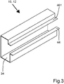
- FIG. 3 shows a support profile of the balcony in a perspective view.
- the carrier profile 12 is the result of a forming process of a thin sheet after six folding processes.
- On the balcony floor support 44 is when installing the A section of the balcony floor underside 402 (not shown in this figure) is placed on the balconies and a balcony floor covering 46, not shown here, is placed on the floor covering support 461 of the support profile during balcony assembly.
- the lower U-shaped section is a structural component of the C-shaped support profile on the short horizontal side.
- This U-shaped section forms a water drain section 34.
- This water drainage section 34 continues over the other support profiles 14, 16, 18 in the entire support profile frame 10. It picks up the water collected by the trough-shaped cassette elements 50 and guided into the carrier profiles and drains it away.
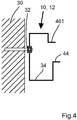
- Figure 4 shows a cross-sectional view of the support profile of the balcony with four vertical stands attached to a building wall by means of a holding system.
- the first support profile 12 has at least one hole in its vertical section. Through this hole, the support profile 12 is connected by means of a holding system 32 having a screw and two washers to a building wall which also has a hole.
- the load on this balcony is mainly borne by the vertical stands.
- the holding system 32 is used only for the lateral fixing of the support profile frame 10 to the building wall 30.
- the statements already made for the water drainage section 34, the floor covering 461 of the support profile and the balcony floor support 44 apply accordingly to this figure.
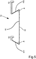
- FIG. 5 shows a central cassette element of the balcony in cross section.
- the central cassette element 54 like the carrier profile 12, is the result of a shaping process of a thin sheet after six folding processes.
- Two coupling legs 64 extend away from a base 60 due to the bend.
- An engaging leg 641 extends from the left edge of the base 60 and an overlapping leg 642 extends from the right edge.
- the engaging leg 66 and the overlapping leg 68 are at a coupling leg angle A of 60 to 70 degrees to the base 60 arranged.
- the coupling leg angle A is the same size due to the folding process.
- the end sections of the engaging leg 641 and the overlapping leg 642 each form a coupling area 62.
- Each coupling area 62 has two sections: a first section is parallel to the base as a result of the folding process. Due to the bend, a second section extends at right angles to this first section and in the direction of the base 60 and forms the end of the coupling area 62.
- the engagement leg 641, the overlapping leg 642 and their two sections of the coupling area 62 extend uniformly along the direction of extension E due to the bend. The interaction of the coupling regions 62 of the engaging leg 641 and the overlapping leg 642 is carried out together with Figure 9 explained.
- the underside of the base 60 forms in particular the visible balcony floor 48 of the underside of the balcony floor.
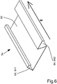
- Figure 6 shows a central cassette element of the balcony in a perspective view. It can be seen very clearly that the coupling leg angle A along the direction of extension E is constant due to the bend.
- the engaging leg 641, the overlapping leg 642 and their two sections of the coupling region 62 are formed, as in FIG Figure 2 and 5 described.
- FIG. 7 an initial cassette element of the balcony in a perspective view.
- the initial cassette element 54 is the result of a forming process of a thin sheet after four bending processes.
- the coupling leg 64 only the engaging leg 641 extends from the left edge of the base 60.
- the engaging leg 641 is designed as in FIG Figure 5 described.
- the other leg is an initial leg 66.
- the initial leg 66 is formed from a single section which, viewed from the base, extends substantially vertically upward.
- the initial leg 66 extends uniformly along the direction of extension E due to the bend. It prevents the water hitting from above (eg rainwater) from running uncontrolled in the direction of the support profile frame 12. This channeling of water is part of the drainage system of the balcony.
- the initial leg 66 increases the Torsional rigidity and thus the stability of the initial cassette element 52.
- Figure 8 shows a final cassette element 56 of the balcony in a perspective view.
- the final cassette element 56 is the result of a forming process of a thin sheet after four folding processes.
- the overlapping leg 642 is formed as the coupling leg 64 on the right edge of the base 60.
- the overlapping leg 642 is designed as in FIG Figure 5 described. The statements made there apply accordingly.
- the other leg arranged on the left edge of the base 60 is an end leg 68.
- the end leg 68 is just like the start leg 66 Figure 7 formed essentially vertically upwards. Everything about the beginning leg 66 Figure 7 What has been said applies correspondingly to the end leg 68.
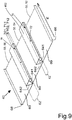
- FIG 9 shows a balcony floor structure 42 formed from three cassette elements without a balcony floor covering.
- the balcony floor structure 42 is formed from the in Figure 7 described initial cartridge element 52, and that in the Figures 5 and 6 described center cassette element 54 and in Figure 8 final cassette element 56 described.
- the in the Figures 5 to 8 The statements made apply accordingly and are therefore not repeated here.
- These three cassette elements 52, 54, 56 are arranged adjacent to one another and overlap in sections.
- Particularly shaped interlocking sections 70 are arranged in overlapping areas.
- the structural design, in particular of the overlapping limbs 642 and the engaging limbs 641 is the result of the folding processes already mentioned and enables the construction of the balcony floor support structure 42 from positively interconnected cassette elements 50 during balcony assembly.
- Each of the three cassette elements 52, 54, 56 has at least the engaging limb 641 with a first form-fitting section 701 and a second form-fitting section 702 or via the overlapping leg 642 a first positive-locking section 711 and a second positive-locking section 712.
- the first positive-locking section 701 of the engaging leg and the first positive-locking section 711 of the overlapping leg are arranged at a defined distance and parallel to the base 60.
- the second form-fitting section 702 of the engaging leg and the second form-fitting section 712 of the overlapping leg extend substantially perpendicularly therefrom in the direction of the respective base 60.
- the second form-fitting sections 702, 712 each form the end of the engaging leg 641 or overlapping leg 642.
- the four form-fitting sections 701, 711, 702, 712 extend as sections of the engaging leg 641 or the overlapping leg 642 along the direction of extension E. Also in the region of the starting leg 66 of the initial cassette element 52 and the end leg 68 of the end cassette element 56, the base 60 lies as part of the underside of the balcony floor in the support profile frame 10 (not shown in this figure) on the balcony floor support 44 there.
- each overlapping leg 642 has a floor covering 462 of the cassette element.
- This floor covering pad 462 is arranged at a defined distance from the base 60 and is formed from the upper side of the coupling region 62 of the overlapping leg 642 parallel to the base 60.
- a fitting, as in FIG Figure 2 described, not shown here, balcony flooring can be placed.
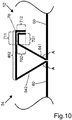
- Figure 10 shows a positive connection of two adjacent cassette elements of the balcony in an enlarged view.
- the area that forms the positive connection between the engaging leg 641 and the overlapping leg 642 is shown hatched for clarity.
- the hatching does not represent a component which is provided in addition to the engaging leg 641 and the overlapping leg 642. Hatched portions of the overlapping leg 642 and engaging leg 641 are shown, which are coupled in a form-fitting manner in a common form-fitting section 70.
- the common positive-locking section 70 is formed from four individual ones Sections.
- the engagement leg 641 extends away from the base 60 of the initial cassette element 52 at a coupling leg angle A.
- the engagement leg 641 has the combination of the first form-fitting section 701 and the second form-fitting section 702 at its end section as a coupling region.
- the first positive-locking section 701 runs parallel to the base 60 and is directed away from the base 60 on the upper side of the engagement leg 641.
- the second positive-locking section 702 extends substantially perpendicularly from the first positive-locking section 701 and extends in the direction of the base 60.
- the overlap leg 642 extends from the base 60 of the initial cassette element 54 at a coupling leg angle A away from the base 60.
- the overlap leg 642 has at its end section the first form-locking section 711 and the adjoining second form-locking section 712. Both form-fitting sections lie in the coupling area of the overlapping leg 642.
- the first form-fitting section 711 runs parallel to the base 60 and is directed on the underside in the direction of the base 60.
- the second form-fitting section 712 extends essentially perpendicularly from the first form-fitting section 711 in the direction of the base 60.
- each overlapping leg 642 preferably has the floor covering pad 462 of the cassette element on the upper side of its section running parallel to the base 60. This floor covering pad 462 is arranged at a defined distance from the base 60.
- a balcony floor covering can be placed on this floor covering support 462 of the cassette element, as already shown in FIG Figure 2 and Figure 9 mentioned.
Landscapes
- Engineering & Computer Science (AREA)
- Architecture (AREA)
- Civil Engineering (AREA)
- Structural Engineering (AREA)
- Physics & Mathematics (AREA)
- Electromagnetism (AREA)
- Steps, Ramps, And Handrails (AREA)
- Floor Finish (AREA)
Claims (10)
- Un balcon pour l'attachement à un mur de bâtiment (30) ayant :- une construction (40) de sol de balcon ayant une partie (401) supérieure de sol de balcon et une partie (402) inférieure de sol de balcon,- un cadre (10) de profilé porteur formé de profilés porteurs (12, 14, 16, 18), formant un appui (44) de sol de balcon pour des sections de la partie (402) inférieure de sol de balcon, et- un système de retenue (32) fixant le cadre de profilé porteur (10), pour attacher le balcon à un mur de bâtiment (30)
dans lequel la construction (40) de sol de balcon a une structure (42) de sol de balcon construite d'au moins deux éléments (50) de caisson s'étendant le long d'une direction (E) commune d'extension (50),
dans lequel chaque élément (50) de caisson vu dans la section transversale perpendiculaire à la direction d'extension (E) est formé de façon- qu'il a une base (60) qui fait une partie de la partie (402) inférieure de sol de balcon et- qu'au moins une jambe (64) de couplage ayant une zone (62) de couplage espacée de la base (60), pour connecter des éléments (50) de caisson avoisinants et / ou pour appuyer un revêtement (46) de sol de balcon sur la structure (42) de sol de balcon s'étende à partir de la base (60), dans lequel chaque zone (62) de couplage a une section (70) à ajustement de forme s'étendant le long de la direction d'extension (E) par laquelle des éléments (50) de caisson avoisinants sont connectés les uns aux autres par la forme,
dans lequel les éléments (50) de caisson, le profilé porteur(12, 14, 16, 18) ou les deux sont formés à partir d'une tôle mince pliée et entre la base (60) et la jambe (64) de couplage des éléments (50) de caisson un angle A de jambe couplage de 60 à 70 degrés est respectivement formé,
dans lequel la section (70) à ajustement de forme de chaque jambe (64) de couplage a une première section (701, 711) à ajustement de forme s'étendant parallèlement à la base (60) de l'élément (50) de caisson et dans lequel une seconde section (702, 712) à ajustement de forme subséquent à la première section (701, 711) à ajustement de forme s'étendant de manière inclinée ou courbée à partir de la première section (701, 711) à ajustement de forme est formée. - Le balcon selon la revendication 1, caractérisé en ce que la jambe (64) de couplage est formée soit comme une jambe (642) de prise ou comme une jambe (641) d'engagement, dans lequel vu à partir de la base (60) de l'élément (50) de caisson en direction des jambes (64) de couplage- à la jambe (642) de prise, la section (70) à ajustement de forme est formée à la partie inférieure de la (62) zone de couplage,- à la jambe (641) d'engagement, la section (70) à ajustement de forme est formée à la partie supérieure de la zone (62) de couplage.
- Le balcon selon la revendication 2, caractérisé en ce qu' une pluralité d'éléments (50) de caisson a respectivement aux deux extrémités de la base (60) une jambe (64) de couplage, dans lequel l'une jambe (64) de couplage est formée comme une jambe (642) de prise et l'autre jambe (64) de couplage est formé comme jambe (641) d'engagement, et la connexion à ajustement de forme est établie aux sections (70) à ajustement de forme des éléments (50) de caisson avoisinants par le couplage de la jambe (642) de prise d'un premier élément (50) de caisson avec la jambe d'engagement d'un deuxième élément (50) de caisson.
- Le balcon selon la revendication 2 ou 3, caractérisé en ce qu' une section de la jambe (642) de prise étant parallèle à la base (60) de l'élément (50) de caisson forme avec sa partie supérieure un appui (462) de revêtement de sol pour un revêtement (46) de sol de balcon.
- Le balcon selon l'une des revendications précédentes, caractérisé en ce que les éléments (50) de caisson avoisinants sont attachés les uns aux autres dans leurs sections (70) à ajustement de forme communes avec des moyens (72) de fixation.
- Le balcon selon l'une des revendications précédentes, caractérisé en ce que les angles A de jambe de couplage de chaque élément (50) de caisson sont formés de la même taille.
- Le balcon selon l'une des revendications précédentes, caractérisé en ce que le cadre (10) de profilé porteur entoure la construction (40) de sol de balcon et les éléments (50) de caisson s'étendent le long de leur direction (E) d'extension en une pièce entre des sections opposées du cadre (10) de profilé porteur.
- Un procédé pour préparer un balcon selon la revendication 1 présentant les étapes suivantes du procédé :- Fournir un cadre (10) de profilé porteur formé à partir de profilés porteurs (12, 14, 16, 18) et formant un appui (44) de sol de balcon pour des sections d'une partie (402) inférieure de sol de balcon ;- Plier au moins deux éléments (50) de caisson de tôle mince, dans lequel chaque élément (50) de caisson s'étend le long d'une direction (E) d'extension prédéterminée par le pliage et chaque élément (50) de caisson vu dans la section transversale à la direction (E) d'extension est formé de manière qu'il a une base (60) qui fait une partie d'une partie (402) inférieure de sol de balcon et qu'au moins une jambe (64) de couplage ayant une zone (62) de couplage espacée de la base (60), pour connecter des éléments (50) de caisson avoisinants et / ou pour appuyer un revêtement (46) de sol de balcon s'étende à partir de la base (60), dans lequel chaque zone (62) de couplage a une section (70) à ajustement de forme pour connecter les éléments (50) de caisson avoisinants, dans lequel entre la base (60) et la jambe (64) de couplage des éléments (50) de caisson un angle A de jambe couplage de 60 à 70 degrés est respectivement formé et dans lequel la section (70) à ajustement de forme de chaque jambe (64) de couplage a une première section (701, 711) à ajustement de forme s'étendant parallèlement à la base (60) de l'élément (50) de caisson,- Insérer un premier élément (50) de caisson sur des sections opposées des appuis (44) de sol de balcon du cadre (10) de profilé porteur,- Insérer un second élément (50) de caisson sur des sections opposées des appuis (44) de sol de balcon du cadre (10) de profilé porteur, dans lequel le second élément (50) de caisson est inséré de sorte que la jambe (64) de couplage du premier élément (50) de caisson va être située à côté de la jambe (64) de couplage du second élément (50) de caisson de sorte que la section (70) à ajustement de forme du premier élément (50) de caisson et le la section (70) à ajustement de forme du second élément (50) de caisson forment une connexion à ajustement de forme et- Fixer les éléments (50) de caisson au cadre (10) de profilé porteur.
- Le procédé selon la revendication 8, caractérisé en ce que
les profilés porteurs (12, 14, 16, 18) de tôle mince formant le cadre (10) de profilé porteur sont pliés,
dans lequel d'abord à partir d'une tôle mince un brin de profilé porteur est plié,
puis à partir du brin de profilé porteur une pluralité de profilés porteurs (12, 14, 16, 18) est scié en onglet
et la majorité des profilés porteurs (12, 14, 16, 18) est connecté pour un cadre (10) de profilé porteur. - Le procédé selon la revendication 8, caractérisé en ce que la pluralité des profilés porteurs (12, 14, 16, 18) est connectée au moyen du soudage, de la brasage ou d'autres procédés appropriés pour le cadre (10) de profilé porteur.
Priority Applications (1)
| Application Number | Priority Date | Filing Date | Title |
|---|---|---|---|
| PL17191931T PL3296475T3 (pl) | 2016-09-19 | 2017-09-19 | Balkon i sposób wytwarzania takiego balkonu |
Applications Claiming Priority (1)
| Application Number | Priority Date | Filing Date | Title |
|---|---|---|---|
| DE102016117578 | 2016-09-19 |
Publications (2)
| Publication Number | Publication Date |
|---|---|
| EP3296475A1 EP3296475A1 (fr) | 2018-03-21 |
| EP3296475B1 true EP3296475B1 (fr) | 2020-08-05 |
Family
ID=59923269
Family Applications (1)
| Application Number | Title | Priority Date | Filing Date |
|---|---|---|---|
| EP17191931.9A Active EP3296475B1 (fr) | 2016-09-19 | 2017-09-19 | Balcon et procédé de fabrication d'un tel balcon |
Country Status (2)
| Country | Link |
|---|---|
| EP (1) | EP3296475B1 (fr) |
| PL (1) | PL3296475T3 (fr) |
Families Citing this family (1)
| Publication number | Priority date | Publication date | Assignee | Title |
|---|---|---|---|---|
| CN113775043B (zh) * | 2021-10-12 | 2022-09-30 | 福建省建融工程建设有限公司 | 一种建筑阳台防护结构 |
Citations (1)
| Publication number | Priority date | Publication date | Assignee | Title |
|---|---|---|---|---|
| DE29920081U1 (de) * | 1999-11-16 | 2000-01-13 | Giller, Jutta, 57368 Lennestadt | Balkon aus Metall |
Family Cites Families (3)
| Publication number | Priority date | Publication date | Assignee | Title |
|---|---|---|---|---|
| JP2001081951A (ja) * | 1999-07-12 | 2001-03-27 | Sekisui Chem Co Ltd | 床構造体 |
| JP2001098745A (ja) * | 1999-10-04 | 2001-04-10 | Sekisui Chem Co Ltd | 床構造体 |
| DK178122B1 (da) * | 2014-07-25 | 2015-06-01 | Krsgaard Invest Aps | Konstruktionselement |
-
2017
- 2017-09-19 EP EP17191931.9A patent/EP3296475B1/fr active Active
- 2017-09-19 PL PL17191931T patent/PL3296475T3/pl unknown
Patent Citations (1)
| Publication number | Priority date | Publication date | Assignee | Title |
|---|---|---|---|---|
| DE29920081U1 (de) * | 1999-11-16 | 2000-01-13 | Giller, Jutta, 57368 Lennestadt | Balkon aus Metall |
Also Published As
| Publication number | Publication date |
|---|---|
| EP3296475A1 (fr) | 2018-03-21 |
| PL3296475T3 (pl) | 2021-02-08 |
Similar Documents
| Publication | Publication Date | Title |
|---|---|---|
| WO2017220650A1 (fr) | Procédé de modernisation d'un escalier mécanique ou d'un trottoir roulant | |
| EP3239431B2 (fr) | Console d'ancrage pour fixer un revetement sur un mur porteur et tole d'une console d'ancrage | |
| EP2486196B1 (fr) | Procédé et dispositif pour l'ajout postérieur d'une partie extérieure en saillie à une partie de bâtiment existante | |
| DE102021101768A1 (de) | Anordnung von gerüstbauteilen | |
| DE2724755A1 (de) | Sturz zur abstuetzung der aeusseren mauerschicht von mauerwerk ueber wandoeffnungen | |
| EP3016843B1 (fr) | Convoyeur aérien équipé de modules de châssis porteur | |
| EP3296475B1 (fr) | Balcon et procédé de fabrication d'un tel balcon | |
| DE102007021159A1 (de) | Rostdeckenschalung zur Einbindung einer Säule | |
| DE9409626U1 (de) | Balkonkonstruktion | |
| AT503358B1 (de) | Anschlusskorb für vorfabrizierte doppelwandelemente | |
| DE60020165T2 (de) | Abstützverfahren für hohlträger und endbefestigung | |
| EP0106297A2 (fr) | Elément de construction pour la fabrication de murs en béton et mur de bâtiment fabriqué avec celui-ci | |
| DE19720637C1 (de) | Verfahren zur Herstellung eines Bauteils aus Stahlbeton und Schalung zur Durchführung des Verfahrens | |
| WO2004059216A1 (fr) | Element de construction prefabrique en particulier element de construction ou de paroi constitue d'un materiau durci et procede de production d'un tel element de construction | |
| EP4194613B1 (fr) | Module de fabrication d'une fondation en béton, utilisation et procédé | |
| DE2422771C3 (de) | Raumfachwerk | |
| AT403820B (de) | Balkon oder ähnlicher anbau sowie verfahren zur nachträglichen herstellung eines balkons oder ähnlichen anbaus | |
| DE2113756A1 (de) | Verfahren zur Herstellung eines fachwerkaehnlichen Traegers | |
| DE202016105596U1 (de) | Tragwerk und Gebäude | |
| DE2728474A1 (de) | Biegesteifer rahmenkoerper | |
| DE102022119025A1 (de) | Befestigungssystem für ein Fassadenelement und Verfahren zur Befestigung bei auskragender Geschoßdecke | |
| EP1260644A2 (fr) | Elément de toiture, bâtiment et procédé pour construire un tel bâtiment | |
| CH645427A5 (en) | Double garage | |
| DE3314626C2 (de) | Halterung für einen Luftkanal und Bausatz dafür | |
| DE202024002501U1 (de) | Stützvorrichtung mit Auffangsicherung |
Legal Events
| Date | Code | Title | Description |
|---|---|---|---|
| PUAI | Public reference made under article 153(3) epc to a published international application that has entered the european phase |
Free format text: ORIGINAL CODE: 0009012 |
|
| STAA | Information on the status of an ep patent application or granted ep patent |
Free format text: STATUS: THE APPLICATION HAS BEEN PUBLISHED |
|
| AK | Designated contracting states |
Kind code of ref document: A1 Designated state(s): AL AT BE BG CH CY CZ DE DK EE ES FI FR GB GR HR HU IE IS IT LI LT LU LV MC MK MT NL NO PL PT RO RS SE SI SK SM TR |
|
| AX | Request for extension of the european patent |
Extension state: BA ME |
|
| STAA | Information on the status of an ep patent application or granted ep patent |
Free format text: STATUS: REQUEST FOR EXAMINATION WAS MADE |
|
| 17P | Request for examination filed |
Effective date: 20180921 |
|
| RBV | Designated contracting states (corrected) |
Designated state(s): AL AT BE BG CH CY CZ DE DK EE ES FI FR GB GR HR HU IE IS IT LI LT LU LV MC MK MT NL NO PL PT RO RS SE SI SK SM TR |
|
| STAA | Information on the status of an ep patent application or granted ep patent |
Free format text: STATUS: EXAMINATION IS IN PROGRESS |
|
| 17Q | First examination report despatched |
Effective date: 20190710 |
|
| RIC1 | Information provided on ipc code assigned before grant |
Ipc: E04D 13/16 20060101ALI20200116BHEP Ipc: E04B 1/00 20060101AFI20200116BHEP Ipc: E04D 11/00 20060101ALI20200116BHEP Ipc: E04D 13/04 20060101ALI20200116BHEP |
|
| GRAP | Despatch of communication of intention to grant a patent |
Free format text: ORIGINAL CODE: EPIDOSNIGR1 |
|
| STAA | Information on the status of an ep patent application or granted ep patent |
Free format text: STATUS: GRANT OF PATENT IS INTENDED |
|
| INTG | Intention to grant announced |
Effective date: 20200305 |
|
| GRAS | Grant fee paid |
Free format text: ORIGINAL CODE: EPIDOSNIGR3 |
|
| GRAA | (expected) grant |
Free format text: ORIGINAL CODE: 0009210 |
|
| STAA | Information on the status of an ep patent application or granted ep patent |
Free format text: STATUS: THE PATENT HAS BEEN GRANTED |
|
| AK | Designated contracting states |
Kind code of ref document: B1 Designated state(s): AL AT BE BG CH CY CZ DE DK EE ES FI FR GB GR HR HU IE IS IT LI LT LU LV MC MK MT NL NO PL PT RO RS SE SI SK SM TR |
|
| REG | Reference to a national code |
Ref country code: GB Ref legal event code: FG4D Free format text: NOT ENGLISH |
|
| REG | Reference to a national code |
Ref country code: CH Ref legal event code: EP |
|
| REG | Reference to a national code |
Ref country code: AT Ref legal event code: REF Ref document number: 1298894 Country of ref document: AT Kind code of ref document: T Effective date: 20200815 |
|
| REG | Reference to a national code |
Ref country code: DE Ref legal event code: R096 Ref document number: 502017006527 Country of ref document: DE |
|
| REG | Reference to a national code |
Ref country code: IE Ref legal event code: FG4D Free format text: LANGUAGE OF EP DOCUMENT: GERMAN |
|
| REG | Reference to a national code |
Ref country code: DE Ref legal event code: R082 Ref document number: 502017006527 Country of ref document: DE Representative=s name: ADARES PATENT- UND RECHTSANWAELTE REININGER & , DE |
|
| REG | Reference to a national code |
Ref country code: LT Ref legal event code: MG4D |
|
| REG | Reference to a national code |
Ref country code: NL Ref legal event code: MP Effective date: 20200805 |
|
| PG25 | Lapsed in a contracting state [announced via postgrant information from national office to epo] |
Ref country code: FI Free format text: LAPSE BECAUSE OF FAILURE TO SUBMIT A TRANSLATION OF THE DESCRIPTION OR TO PAY THE FEE WITHIN THE PRESCRIBED TIME-LIMIT Effective date: 20200805 Ref country code: LT Free format text: LAPSE BECAUSE OF FAILURE TO SUBMIT A TRANSLATION OF THE DESCRIPTION OR TO PAY THE FEE WITHIN THE PRESCRIBED TIME-LIMIT Effective date: 20200805 Ref country code: BG Free format text: LAPSE BECAUSE OF FAILURE TO SUBMIT A TRANSLATION OF THE DESCRIPTION OR TO PAY THE FEE WITHIN THE PRESCRIBED TIME-LIMIT Effective date: 20201105 Ref country code: ES Free format text: LAPSE BECAUSE OF FAILURE TO SUBMIT A TRANSLATION OF THE DESCRIPTION OR TO PAY THE FEE WITHIN THE PRESCRIBED TIME-LIMIT Effective date: 20200805 Ref country code: NO Free format text: LAPSE BECAUSE OF FAILURE TO SUBMIT A TRANSLATION OF THE DESCRIPTION OR TO PAY THE FEE WITHIN THE PRESCRIBED TIME-LIMIT Effective date: 20201105 Ref country code: GR Free format text: LAPSE BECAUSE OF FAILURE TO SUBMIT A TRANSLATION OF THE DESCRIPTION OR TO PAY THE FEE WITHIN THE PRESCRIBED TIME-LIMIT Effective date: 20201106 Ref country code: PT Free format text: LAPSE BECAUSE OF FAILURE TO SUBMIT A TRANSLATION OF THE DESCRIPTION OR TO PAY THE FEE WITHIN THE PRESCRIBED TIME-LIMIT Effective date: 20201207 Ref country code: HR Free format text: LAPSE BECAUSE OF FAILURE TO SUBMIT A TRANSLATION OF THE DESCRIPTION OR TO PAY THE FEE WITHIN THE PRESCRIBED TIME-LIMIT Effective date: 20200805 Ref country code: SE Free format text: LAPSE BECAUSE OF FAILURE TO SUBMIT A TRANSLATION OF THE DESCRIPTION OR TO PAY THE FEE WITHIN THE PRESCRIBED TIME-LIMIT Effective date: 20200805 |
|
| PG25 | Lapsed in a contracting state [announced via postgrant information from national office to epo] |
Ref country code: RS Free format text: LAPSE BECAUSE OF FAILURE TO SUBMIT A TRANSLATION OF THE DESCRIPTION OR TO PAY THE FEE WITHIN THE PRESCRIBED TIME-LIMIT Effective date: 20200805 Ref country code: LV Free format text: LAPSE BECAUSE OF FAILURE TO SUBMIT A TRANSLATION OF THE DESCRIPTION OR TO PAY THE FEE WITHIN THE PRESCRIBED TIME-LIMIT Effective date: 20200805 Ref country code: NL Free format text: LAPSE BECAUSE OF FAILURE TO SUBMIT A TRANSLATION OF THE DESCRIPTION OR TO PAY THE FEE WITHIN THE PRESCRIBED TIME-LIMIT Effective date: 20200805 Ref country code: IS Free format text: LAPSE BECAUSE OF FAILURE TO SUBMIT A TRANSLATION OF THE DESCRIPTION OR TO PAY THE FEE WITHIN THE PRESCRIBED TIME-LIMIT Effective date: 20201205 |
|
| PG25 | Lapsed in a contracting state [announced via postgrant information from national office to epo] |
Ref country code: DK Free format text: LAPSE BECAUSE OF FAILURE TO SUBMIT A TRANSLATION OF THE DESCRIPTION OR TO PAY THE FEE WITHIN THE PRESCRIBED TIME-LIMIT Effective date: 20200805 Ref country code: CZ Free format text: LAPSE BECAUSE OF FAILURE TO SUBMIT A TRANSLATION OF THE DESCRIPTION OR TO PAY THE FEE WITHIN THE PRESCRIBED TIME-LIMIT Effective date: 20200805 Ref country code: RO Free format text: LAPSE BECAUSE OF FAILURE TO SUBMIT A TRANSLATION OF THE DESCRIPTION OR TO PAY THE FEE WITHIN THE PRESCRIBED TIME-LIMIT Effective date: 20200805 Ref country code: SM Free format text: LAPSE BECAUSE OF FAILURE TO SUBMIT A TRANSLATION OF THE DESCRIPTION OR TO PAY THE FEE WITHIN THE PRESCRIBED TIME-LIMIT Effective date: 20200805 Ref country code: EE Free format text: LAPSE BECAUSE OF FAILURE TO SUBMIT A TRANSLATION OF THE DESCRIPTION OR TO PAY THE FEE WITHIN THE PRESCRIBED TIME-LIMIT Effective date: 20200805 |
|
| REG | Reference to a national code |
Ref country code: CH Ref legal event code: PL |
|
| REG | Reference to a national code |
Ref country code: DE Ref legal event code: R097 Ref document number: 502017006527 Country of ref document: DE |
|
| PG25 | Lapsed in a contracting state [announced via postgrant information from national office to epo] |
Ref country code: AL Free format text: LAPSE BECAUSE OF FAILURE TO SUBMIT A TRANSLATION OF THE DESCRIPTION OR TO PAY THE FEE WITHIN THE PRESCRIBED TIME-LIMIT Effective date: 20200805 Ref country code: MC Free format text: LAPSE BECAUSE OF FAILURE TO SUBMIT A TRANSLATION OF THE DESCRIPTION OR TO PAY THE FEE WITHIN THE PRESCRIBED TIME-LIMIT Effective date: 20200805 |
|
| PLBE | No opposition filed within time limit |
Free format text: ORIGINAL CODE: 0009261 |
|
| STAA | Information on the status of an ep patent application or granted ep patent |
Free format text: STATUS: NO OPPOSITION FILED WITHIN TIME LIMIT |
|
| REG | Reference to a national code |
Ref country code: BE Ref legal event code: MM Effective date: 20200930 |
|
| PG25 | Lapsed in a contracting state [announced via postgrant information from national office to epo] |
Ref country code: LU Free format text: LAPSE BECAUSE OF NON-PAYMENT OF DUE FEES Effective date: 20200919 Ref country code: SK Free format text: LAPSE BECAUSE OF FAILURE TO SUBMIT A TRANSLATION OF THE DESCRIPTION OR TO PAY THE FEE WITHIN THE PRESCRIBED TIME-LIMIT Effective date: 20200805 |
|
| 26N | No opposition filed |
Effective date: 20210507 |
|
| PG25 | Lapsed in a contracting state [announced via postgrant information from national office to epo] |
Ref country code: IT Free format text: LAPSE BECAUSE OF FAILURE TO SUBMIT A TRANSLATION OF THE DESCRIPTION OR TO PAY THE FEE WITHIN THE PRESCRIBED TIME-LIMIT Effective date: 20200805 |
|
| PG25 | Lapsed in a contracting state [announced via postgrant information from national office to epo] |
Ref country code: SI Free format text: LAPSE BECAUSE OF FAILURE TO SUBMIT A TRANSLATION OF THE DESCRIPTION OR TO PAY THE FEE WITHIN THE PRESCRIBED TIME-LIMIT Effective date: 20200805 Ref country code: LI Free format text: LAPSE BECAUSE OF NON-PAYMENT OF DUE FEES Effective date: 20200930 Ref country code: IE Free format text: LAPSE BECAUSE OF NON-PAYMENT OF DUE FEES Effective date: 20200919 Ref country code: CH Free format text: LAPSE BECAUSE OF NON-PAYMENT OF DUE FEES Effective date: 20200930 Ref country code: BE Free format text: LAPSE BECAUSE OF NON-PAYMENT OF DUE FEES Effective date: 20200930 |
|
| PG25 | Lapsed in a contracting state [announced via postgrant information from national office to epo] |
Ref country code: TR Free format text: LAPSE BECAUSE OF FAILURE TO SUBMIT A TRANSLATION OF THE DESCRIPTION OR TO PAY THE FEE WITHIN THE PRESCRIBED TIME-LIMIT Effective date: 20200805 Ref country code: MT Free format text: LAPSE BECAUSE OF FAILURE TO SUBMIT A TRANSLATION OF THE DESCRIPTION OR TO PAY THE FEE WITHIN THE PRESCRIBED TIME-LIMIT Effective date: 20200805 Ref country code: CY Free format text: LAPSE BECAUSE OF FAILURE TO SUBMIT A TRANSLATION OF THE DESCRIPTION OR TO PAY THE FEE WITHIN THE PRESCRIBED TIME-LIMIT Effective date: 20200805 |
|
| PG25 | Lapsed in a contracting state [announced via postgrant information from national office to epo] |
Ref country code: MK Free format text: LAPSE BECAUSE OF FAILURE TO SUBMIT A TRANSLATION OF THE DESCRIPTION OR TO PAY THE FEE WITHIN THE PRESCRIBED TIME-LIMIT Effective date: 20200805 |
|
| P01 | Opt-out of the competence of the unified patent court (upc) registered |
Effective date: 20230609 |
|
| REG | Reference to a national code |
Ref country code: AT Ref legal event code: MM01 Ref document number: 1298894 Country of ref document: AT Kind code of ref document: T Effective date: 20220919 |
|
| PG25 | Lapsed in a contracting state [announced via postgrant information from national office to epo] |
Ref country code: AT Free format text: LAPSE BECAUSE OF NON-PAYMENT OF DUE FEES Effective date: 20220919 |
|
| PGFP | Annual fee paid to national office [announced via postgrant information from national office to epo] |
Ref country code: DE Payment date: 20250813 Year of fee payment: 9 |
|
| PGFP | Annual fee paid to national office [announced via postgrant information from national office to epo] |
Ref country code: PL Payment date: 20250813 Year of fee payment: 9 |
|
| PGFP | Annual fee paid to national office [announced via postgrant information from national office to epo] |
Ref country code: GB Payment date: 20250923 Year of fee payment: 9 |
|
| PGFP | Annual fee paid to national office [announced via postgrant information from national office to epo] |
Ref country code: FR Payment date: 20250925 Year of fee payment: 9 |