EP0905490B1 - Contrôleur de composantes optiques - Google Patents
Contrôleur de composantes optiques Download PDFInfo
- Publication number
- EP0905490B1 EP0905490B1 EP98107197A EP98107197A EP0905490B1 EP 0905490 B1 EP0905490 B1 EP 0905490B1 EP 98107197 A EP98107197 A EP 98107197A EP 98107197 A EP98107197 A EP 98107197A EP 0905490 B1 EP0905490 B1 EP 0905490B1
- Authority
- EP
- European Patent Office
- Prior art keywords
- optical
- wavelength
- optical component
- tester
- laser source
- Prior art date
- Legal status (The legal status is an assumption and is not a legal conclusion. Google has not performed a legal analysis and makes no representation as to the accuracy of the status listed.)
- Expired - Lifetime
Links
- 230000003287 optical effect Effects 0.000 title claims description 140
- 230000004044 response Effects 0.000 claims description 28
- 230000001419 dependent effect Effects 0.000 claims description 11
- 238000000034 method Methods 0.000 claims description 9
- 238000012545 processing Methods 0.000 claims description 7
- 239000000835 fiber Substances 0.000 claims description 4
- 238000004891 communication Methods 0.000 claims description 3
- 230000003213 activating effect Effects 0.000 claims description 2
- 230000003993 interaction Effects 0.000 claims description 2
- 239000004065 semiconductor Substances 0.000 claims description 2
- 230000011664 signaling Effects 0.000 claims 1
- 238000005259 measurement Methods 0.000 description 15
- 238000012360 testing method Methods 0.000 description 5
- 230000006399 behavior Effects 0.000 description 3
- 230000003595 spectral effect Effects 0.000 description 3
- 238000001228 spectrum Methods 0.000 description 3
- 238000010586 diagram Methods 0.000 description 2
- 239000013307 optical fiber Substances 0.000 description 2
- 229910052691 Erbium Inorganic materials 0.000 description 1
- 238000003491 array Methods 0.000 description 1
- 230000008033 biological extinction Effects 0.000 description 1
- BJQHLKABXJIVAM-UHFFFAOYSA-N bis(2-ethylhexyl) phthalate Chemical compound CCCCC(CC)COC(=O)C1=CC=CC=C1C(=O)OCC(CC)CCCC BJQHLKABXJIVAM-UHFFFAOYSA-N 0.000 description 1
- 238000012937 correction Methods 0.000 description 1
- 230000008878 coupling Effects 0.000 description 1
- 238000010168 coupling process Methods 0.000 description 1
- 238000005859 coupling reaction Methods 0.000 description 1
- UYAHIZSMUZPPFV-UHFFFAOYSA-N erbium Chemical compound [Er] UYAHIZSMUZPPFV-UHFFFAOYSA-N 0.000 description 1
- 230000001747 exhibiting effect Effects 0.000 description 1
- 230000000977 initiatory effect Effects 0.000 description 1
- 238000012986 modification Methods 0.000 description 1
- 230000004048 modification Effects 0.000 description 1
- 238000012805 post-processing Methods 0.000 description 1
- 238000000926 separation method Methods 0.000 description 1
Images

Classifications
-
- G—PHYSICS
- G01—MEASURING; TESTING
- G01M—TESTING STATIC OR DYNAMIC BALANCE OF MACHINES OR STRUCTURES; TESTING OF STRUCTURES OR APPARATUS, NOT OTHERWISE PROVIDED FOR
- G01M11/00—Testing of optical apparatus; Testing structures by optical methods not otherwise provided for
- G01M11/30—Testing of optical devices, constituted by fibre optics or optical waveguides
- G01M11/33—Testing of optical devices, constituted by fibre optics or optical waveguides with a light emitter being disposed at one fibre or waveguide end-face, and a light receiver at the other end-face
Definitions
- a pump coupler at the input of an optical amplifier may have a spectral bandwidth of 50 nm or more, whereas a Wavelength-Division-Multiplexing (WDM) de-multiplexer may have a spectral bandwidth of only 0.2 nm for each of its channels.
- WDM Wavelength-Division-Multiplexing
- modem optical devices such as WDM or Dense-WDM (DWDM) devices, may provide one input and multiple outputs, where each output has a different wavelength passband characteristics. A measurement of such a device often demands several thousand points per output to achieve the required characteristic, with one powermeter per output which have to obtain the measurement points synchronously.
- Known measurement setups for characterizing wavelength dependent optical components are normally based on a tunable laser source in combination with a wavelength meter, a tracking filter and an optical power meter (loc. cit. page 360) and connected via standard interfaces (e.g. HPIB).
- a tunable laser source instead of using a tunable laser source, a broadband light source can be applied in combination with an optical spectrum analyzer (loc cit. page 368f), however, with a limited resolution bandwidth (approximately 0.1...0.05 nm) in contrast to the tunable laser sources (approximately 10 -6 nm).
- EP-A-548 935 discloses an apparatus for measuring the effective refractive index in optical fibers.
- the apparatus comprises a tunable laser source for providing a stimulus signal to the optical component and a receiver for receiving a response of the optical component on the stimulus signal.
- a control unit is coupled to the tunable laser source and the receiver for controlling the functioning thereof.
- the output 20A of the tunable laser source 20 provides the output for applying the stimulus signal to the DUT 100.
- the wavemeter 30 provides an additional output (not shown) for applying the stimulus signal to the DUT 100.
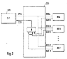
- the signal processor 170 handles the precise time critical emission of triggering signals, so that each laser signals is emitted at a certain (requested) point of time and that each measuring result of the response units 80A...80Z can be clearly assigned to a specific laser input signal for the DUT 100 at a certain wavelength determined by the wavemeter 30.
- the control unit 60 might further comprise a trigger unit (TRIGGER) 200 for emitting trigger signals for activating and initiating respective functionalities of the functional units, such as the tunable laser source 20, the wavemeter 30, the attenuator 40, and the response units 80A...80Z.
- the trigger unit 200 is therefore coupled via a bus 205 with the micro-controller 150, and thus, via the bus 160 to the signal processor 170 and via the bus 70 to the response units 80A...80Z.
- the trigger unit 200 is preferably able to connect internal and/or external modules to each other and is preferably level or edge controlled.
- the trigger unit 200 is preferably embodied in a way that substantially all functionality of the hardware components can be set up and modified by software means, so that the trigger unit 200 is programmable according to the actual demands. This can be accomplished e.g. by using field programmable gate arrays (FPGAs) exhibiting low costs and a low space demand.
- FPGAs field programmable gate arrays
Landscapes
- Physics & Mathematics (AREA)
- Optics & Photonics (AREA)
- Chemical & Material Sciences (AREA)
- Analytical Chemistry (AREA)
- General Physics & Mathematics (AREA)
- Semiconductor Lasers (AREA)
- Testing Of Optical Devices Or Fibers (AREA)
Claims (12)
- Un testeur (10) de composants optiques pour déterminer les caractéristiques d'un composant optique (100) qui dépendent de la longueur d'onde, comprenant:caractérisé en ce quecomme unités fonctionnelles (20 à 40, 80):une source laser accordable (20) pour envoyer un signal de stimulus au composant optique (100), etune ou plusieurs unités de réponse (80A à 80Z) pour recevoir une réponse du composant optique (100) au signal de stimulus, etune unité de commande (60) couplée aux unités fonctionnelles (20 à 40, 80) pour commander leur fonctionnement,
l'unité de commande (60) comprend un microcontrôleur (150) connecté à un processeur (170) de signaux d'une façon telle que le processeur (170) de signaux est connecté aux unités fonctionnelles (20 à 40, 80) et est agencé pour traiter toutes les opérations critiques de synchronisation à l'intérieur du testeur (10). - Le testeur (10) de composants optiques selon la revendication 1, dans lequel l'unité de commande (60) prend de plus en charge la communication entre les unités fonctionnelles (20 à 40, 80) et fournit une information pour l'interaction entre les unités fonctionnelles (20 à 40, 80).
- Le testeur (10) de composants optiques selon la revendication 1 ou 2, dans lequel l'unité de commande (60) comprend une unité de déclenchement (200) pour émettre des signaux de déclenchement afin d'activer les unités fonctionnelles (20 à 40, 80).
- Le testeur (10) de composants optiques selon la revendication 3, dans lequel l'unité de déclenchement (200) est couplée au processeur (170) de signaux et/ou aux unités fonctionnelles (20 à 40, 80) pour en recevoir un signal d'entrée de commande et pour émettre vers eux un signal de sortie de commande.
- Le testeur (10) de composants optiques selon l'une quelconque des revendications 1 à 4, qui comprend en outre comme unités fonctionnelles (20 à 40, 80), un ondemètre (30) et/ou un atténuateur (40).
- Le testeur (10) de composants optiques selon la revendication 5, dans lequel une sortie (20A) de la source laser accordable (20) est directement couplée à une entrée (30A) de l'ondemètre (30) et/ou à une entrée (40A) de l'atténuateur (40), et une sortie (40B) de l'atténuateur (40) constitue une sortie externe du testeur (10) de composants optiques pour appliquer le signal de stimulus au composant optique (100).
- Le testeur (10) de composants optiques selon la revendication 5 ou 6, dans lequel la source laser accordable (20) comprend un résonateur optique à amplificateur par semi-conducteurs et/ou par fibres pour émettre un faisceau laser, un miroir dépendant de la longueur d'onde pour recevoir le faisceau laser et réfléchir en retour un faisceau laser à longueurs d'ondes séparées, et un diviseur de faisceaux pour diviser le faisceau laser à longueurs d'ondes séparées en un faisceau de rétroaction (20A) dirigé vers l'amplificateur et un premier faisceau de sortie (20B) à coupler à partir du résonateur optique de la source laser accordable (20).
- Le testeur (10) de composants optiques selon l'une quelconque des revendications 5 à 7, dans lequel l'ondemètre (30) de mesure d'une longueur d'onde d'un premier faisceau optique comprend:un premier composant optique qui est agencé dans ledit premier faisceau optique ou dans une partie de celui-ci et qui engendre un deuxième faisceau optique d'une première puissance optique, telle que ladite première puissance optique dudit deuxième faisceau optique dépend de la longueur d'onde dudit premier faisceau optique,un premier détecteur de puissance qui détecte la puissance optique dudit deuxième faisceau optique,un premier dispositif d'allocation qui alloue une longueur d'onde à ladite première puissance optique détectée sur la base de la dépendance de la puissance optique dudit deuxième faisceau optique, qui est engendré par ledit premier composant optique, vis-à-vis de la longueur d'onde dudit premier faisceau optique à mesurer,un deuxième composant optique est agencé dans ledit premier faisceau optique ou dans une partie de celui-ci et qui engendre un troisième faisceau optique d'une deuxième puissance optique, tel que ladite puissance optique dudit troisième faisceau optique dépend de la longueur d'onde dudit troisième faisceau optique;un deuxième détecteur de puissance qui détecte la puissance optique dudit troisième faisceau optique,un deuxième dispositif d'allocation qui alloue une longueur d'onde à ladite deuxième puissance optique détectée sur la base de la dépendance de ladite deuxième puissance optique, dudit troisième faisceau optique qui est engendré par ledit deuxième composant optique, vis-à-vis de la longueur d'onde dudit premier faisceau optique à mesurer,de sorte que ladite puissance optique engendrée par lesdits premier et deuxième composants optiques oscille périodiquement à une longueur d'onde croissante, et ledit troisième faisceau optique est retardé par rapport audit deuxième faisceau optique.
- Le testeur (10) de composants optiques selon l'une quelconque des revendications 1 à 8, dans lequel l'unité de commande (60) est couplée à une mémoire (130) qui comprend des données mémorisées de calibrage, de calibrage préalable et/ou d'installation.
- Un procédé de détermination des caractéristiques d'un composant optique (100) qui dépendent de la longueur d'onde, au moyen d'un testeur (10) de composants optiques, selon l'une quelconque des revendications 1 à 9, le procédé comprenant les étapes consistant à:envoyer un signal de stimulus au composant optique (100),recevoir une réponse du composant optique (100) au signal de stimulus, etcommander l'envoi du signal de stimulus et la réception de la réponse du signal de stimulus en divisant les opérations internes au testeur (10) de composant optique en opérations critiques quant à la synchronisation et non critiques quant à la synchronisation.
- Un procédé de détermination des caractéristiques d'un composant optique (100) qui dépendent de la longueur d'onde au moyen d'un testeur (10) de composants optiques selon la revendication 10, dans lequel des données de calibrage et/ou de calibrage préalable pour le processeur (170) de signaux sont chargées dans une unité de mémoire du processeur (170) de signaux.
- Un procédé de détermination des caractéristiques d'un composant optique (100) qui dépendent de la longueur d'onde au moyen d'un testeur (10) de composants optiques selon l'une quelconque des revendications 5 à 9, dans lequel un stimulus et/ou un balayage de longueur d'onde de réponse est exécuté:dans un mode linéaire vis-à-vis des longueurs d'ondes en appliquant l'ondemètre (30) pour assurer un accord linéaire en longueur d'onde de la source laser accordable (20), oudans un mode à vitesse constante en déplaçant la source laser accordable (20) d'une première longueur d'onde à une deuxième, de sorte que l'ondemètre (20) mesure la longueur d'onde à chaque point de mesure.
Priority Applications (4)
| Application Number | Priority Date | Filing Date | Title |
|---|---|---|---|
| DE69800492T DE69800492T2 (de) | 1998-04-21 | 1998-04-21 | Prüfvorrichtung für optische Komponenten |
| EP98107197A EP0905490B1 (fr) | 1998-04-21 | 1998-04-21 | Contrôleur de composantes optiques |
| JP11109099A JP2000035376A (ja) | 1998-04-21 | 1999-04-16 | 光学部品テスタ |
| US09/294,555 US6538778B1 (en) | 1998-04-21 | 1999-04-20 | Optical component tester |
Applications Claiming Priority (1)
| Application Number | Priority Date | Filing Date | Title |
|---|---|---|---|
| EP98107197A EP0905490B1 (fr) | 1998-04-21 | 1998-04-21 | Contrôleur de composantes optiques |
Publications (2)
| Publication Number | Publication Date |
|---|---|
| EP0905490A1 EP0905490A1 (fr) | 1999-03-31 |
| EP0905490B1 true EP0905490B1 (fr) | 2001-01-17 |
Family
ID=8231788
Family Applications (1)
| Application Number | Title | Priority Date | Filing Date |
|---|---|---|---|
| EP98107197A Expired - Lifetime EP0905490B1 (fr) | 1998-04-21 | 1998-04-21 | Contrôleur de composantes optiques |
Country Status (4)
| Country | Link |
|---|---|
| US (1) | US6538778B1 (fr) |
| EP (1) | EP0905490B1 (fr) |
| JP (1) | JP2000035376A (fr) |
| DE (1) | DE69800492T2 (fr) |
Families Citing this family (58)
| Publication number | Priority date | Publication date | Assignee | Title |
|---|---|---|---|---|
| US6597449B1 (en) * | 2000-01-31 | 2003-07-22 | New Focus, Inc. | Real time process control of optical components using linearly swept tunable laser |
| JP4842447B2 (ja) * | 2001-03-06 | 2011-12-21 | 株式会社アドバンテスト | 光波長測定装置、方法、プログラムおよび該プログラムを記録した記録媒体 |
| EP1235062B1 (fr) * | 2001-11-30 | 2004-03-31 | Agilent Technologies, Inc. (a Delaware corporation) | Mesure de dispositifs optiques multiport |
| JP2003254864A (ja) | 2002-03-04 | 2003-09-10 | Ando Electric Co Ltd | 波長依存性測定装置 |
| US9867530B2 (en) | 2006-08-14 | 2018-01-16 | Volcano Corporation | Telescopic side port catheter device with imaging system and method for accessing side branch occlusions |
| US8395781B2 (en) | 2007-07-12 | 2013-03-12 | Volcano Corporation | Automatic calibration systems and methods of use |
| US10219780B2 (en) * | 2007-07-12 | 2019-03-05 | Volcano Corporation | OCT-IVUS catheter for concurrent luminal imaging |
| EP2178442B1 (fr) | 2007-07-12 | 2017-09-06 | Volcano Corporation | Cathéter pour imagerie in-vivo |
| US9596993B2 (en) | 2007-07-12 | 2017-03-21 | Volcano Corporation | Automatic calibration systems and methods of use |
| JP5481376B2 (ja) | 2007-07-12 | 2014-04-23 | ヴォルカノ コーポレイション | 光コヒーレンストモグラフィー用のクロック制御方法 |
| EP2350602A1 (fr) * | 2008-10-27 | 2011-08-03 | Telefonaktiebolaget L M Ericsson (Publ) | Procédé et appareil pour la détermination d'une caractéristique de transfert de signal le long d'un trajet de lumière dans un réseau optique |
| CN101908942B (zh) * | 2009-06-05 | 2014-10-08 | 华为技术有限公司 | 一种损伤信息传送方法、节点和网络系统 |
| US8233215B2 (en) * | 2009-08-18 | 2012-07-31 | Ciena Corporation | Optical module manufacturing and testing systems and methods |
| US11141063B2 (en) | 2010-12-23 | 2021-10-12 | Philips Image Guided Therapy Corporation | Integrated system architectures and methods of use |
| US11040140B2 (en) | 2010-12-31 | 2021-06-22 | Philips Image Guided Therapy Corporation | Deep vein thrombosis therapeutic methods |
| WO2013033592A1 (fr) | 2011-08-31 | 2013-03-07 | Volcano Corporation | Joint rotatif électro-optique et procédés d'utilisation |
| CA2887421A1 (fr) | 2012-10-05 | 2014-04-10 | David Welford | Systemes et procedes pour amplifier la lumiere |
| US20140100454A1 (en) | 2012-10-05 | 2014-04-10 | Volcano Corporation | Methods and systems for establishing parameters for three-dimensional imaging |
| US10070827B2 (en) | 2012-10-05 | 2018-09-11 | Volcano Corporation | Automatic image playback |
| US9286673B2 (en) | 2012-10-05 | 2016-03-15 | Volcano Corporation | Systems for correcting distortions in a medical image and methods of use thereof |
| US11272845B2 (en) | 2012-10-05 | 2022-03-15 | Philips Image Guided Therapy Corporation | System and method for instant and automatic border detection |
| US9367965B2 (en) | 2012-10-05 | 2016-06-14 | Volcano Corporation | Systems and methods for generating images of tissue |
| US9307926B2 (en) | 2012-10-05 | 2016-04-12 | Volcano Corporation | Automatic stent detection |
| US9292918B2 (en) | 2012-10-05 | 2016-03-22 | Volcano Corporation | Methods and systems for transforming luminal images |
| US9858668B2 (en) | 2012-10-05 | 2018-01-02 | Volcano Corporation | Guidewire artifact removal in images |
| US10568586B2 (en) | 2012-10-05 | 2020-02-25 | Volcano Corporation | Systems for indicating parameters in an imaging data set and methods of use |
| US9324141B2 (en) | 2012-10-05 | 2016-04-26 | Volcano Corporation | Removal of A-scan streaking artifact |
| US9840734B2 (en) | 2012-10-22 | 2017-12-12 | Raindance Technologies, Inc. | Methods for analyzing DNA |
| JP6322210B2 (ja) | 2012-12-13 | 2018-05-09 | ボルケーノ コーポレイション | 標的化された挿管のためのデバイス、システム、および方法 |
| US10939826B2 (en) | 2012-12-20 | 2021-03-09 | Philips Image Guided Therapy Corporation | Aspirating and removing biological material |
| US9709379B2 (en) | 2012-12-20 | 2017-07-18 | Volcano Corporation | Optical coherence tomography system that is reconfigurable between different imaging modes |
| US10595820B2 (en) | 2012-12-20 | 2020-03-24 | Philips Image Guided Therapy Corporation | Smooth transition catheters |
| US10942022B2 (en) | 2012-12-20 | 2021-03-09 | Philips Image Guided Therapy Corporation | Manual calibration of imaging system |
| WO2014113188A2 (fr) | 2012-12-20 | 2014-07-24 | Jeremy Stigall | Localisation d'images intravasculaires |
| US11406498B2 (en) | 2012-12-20 | 2022-08-09 | Philips Image Guided Therapy Corporation | Implant delivery system and implants |
| EP2934280B1 (fr) | 2012-12-21 | 2022-10-19 | Mai, Jerome | Imagerie à ultrasons pourvue d'une densité de ligne variable |
| CA2896004A1 (fr) | 2012-12-21 | 2014-06-26 | Nathaniel J. Kemp | Mise en tampon optique efficace en energie utilisant un commutateur optique |
| US9486143B2 (en) | 2012-12-21 | 2016-11-08 | Volcano Corporation | Intravascular forward imaging device |
| WO2014099672A1 (fr) | 2012-12-21 | 2014-06-26 | Andrew Hancock | Système et procédé pour le traitement multivoie de signaux d'image |
| US9612105B2 (en) | 2012-12-21 | 2017-04-04 | Volcano Corporation | Polarization sensitive optical coherence tomography system |
| EP2936626A4 (fr) | 2012-12-21 | 2016-08-17 | David Welford | Systèmes et procédés permettant de réduire une émission de longueur d'onde de lumière |
| JP2016502884A (ja) | 2012-12-21 | 2016-02-01 | ダグラス メイヤー, | 延在カテーテル本体テレスコープを有する回転可能超音波撮像カテーテル |
| EP2936426B1 (fr) | 2012-12-21 | 2021-10-13 | Jason Spencer | Système et procédé de traitement graphique de données médicales |
| WO2014100530A1 (fr) | 2012-12-21 | 2014-06-26 | Whiseant Chester | Système et procédé pour l'orientation et le fonctionnement de cathéter |
| US10058284B2 (en) | 2012-12-21 | 2018-08-28 | Volcano Corporation | Simultaneous imaging, monitoring, and therapy |
| US10226597B2 (en) | 2013-03-07 | 2019-03-12 | Volcano Corporation | Guidewire with centering mechanism |
| WO2014138555A1 (fr) | 2013-03-07 | 2014-09-12 | Bernhard Sturm | Segmentation multimodale dans des images intravasculaires |
| US20140276923A1 (en) | 2013-03-12 | 2014-09-18 | Volcano Corporation | Vibrating catheter and methods of use |
| US10638939B2 (en) | 2013-03-12 | 2020-05-05 | Philips Image Guided Therapy Corporation | Systems and methods for diagnosing coronary microvascular disease |
| US9301687B2 (en) | 2013-03-13 | 2016-04-05 | Volcano Corporation | System and method for OCT depth calibration |
| JP6339170B2 (ja) | 2013-03-13 | 2018-06-06 | ジンヒョン パーク | 回転式血管内超音波装置から画像を生成するためのシステム及び方法 |
| US11026591B2 (en) | 2013-03-13 | 2021-06-08 | Philips Image Guided Therapy Corporation | Intravascular pressure sensor calibration |
| US10219887B2 (en) | 2013-03-14 | 2019-03-05 | Volcano Corporation | Filters with echogenic characteristics |
| US12343198B2 (en) | 2013-03-14 | 2025-07-01 | Philips Image Guided Therapy Corporation | Delivery catheter having imaging capabilities |
| US20160030151A1 (en) | 2013-03-14 | 2016-02-04 | Volcano Corporation | Filters with echogenic characteristics |
| US10292677B2 (en) | 2013-03-14 | 2019-05-21 | Volcano Corporation | Endoluminal filter having enhanced echogenic properties |
| US11329722B2 (en) | 2020-03-27 | 2022-05-10 | Relative Dynamics Incorporated | Optical terminals |
| US12607540B2 (en) | 2020-04-14 | 2026-04-21 | Jabil Inc. | Optical back reflection diagnostics for micro optical components |
Family Cites Families (23)
| Publication number | Priority date | Publication date | Assignee | Title |
|---|---|---|---|---|
| US4664522A (en) * | 1984-08-24 | 1987-05-12 | Guided Wave, Inc. | Optical waveguide spectrum analyzer and method |
| JPS61147940A (ja) * | 1984-12-21 | 1986-07-05 | Komatsu Ltd | ボス部材溶接用母材及びその製造方法 |
| JPS63285442A (ja) * | 1987-05-18 | 1988-11-22 | Anritsu Corp | 波長分散測定器 |
| US4875859A (en) * | 1988-01-13 | 1989-10-24 | Hewlett-Packard Company | Method and apparatus for guiding a user during setup of a signal measurement system |
| US5069544A (en) * | 1990-04-12 | 1991-12-03 | Minnesota Mining And Manufacturing Company | Adaptive pulse width optical fault finder |
| US5032025A (en) * | 1990-05-07 | 1991-07-16 | Tektronix, Inc. | Wavelength normalization of fiber-optic loss measurements |
| US5291884A (en) * | 1991-02-07 | 1994-03-08 | Minnesota Mining And Manufacturing Company | Apparatus for measuring a blood parameter |
| JPH04285836A (ja) * | 1991-03-13 | 1992-10-09 | Anritsu Corp | 光ファイバ伝送特性測定装置 |
| US5179420A (en) * | 1991-06-07 | 1993-01-12 | Bell Canada | Optical time domain reflectometer using a tunable optical source |
| US5357333A (en) * | 1991-12-23 | 1994-10-18 | Cselt-Centro Studi E Laboratori Telecomunicazioni Spa | Apparatus for measuring the effective refractive index in optical fibers |
| JPH0658817A (ja) * | 1992-08-12 | 1994-03-04 | Yokogawa Electric Corp | 光波長計 |
| JPH06140717A (ja) * | 1992-10-23 | 1994-05-20 | Ando Electric Co Ltd | 外部共振器型半導体レーザ光源 |
| US5546325A (en) * | 1993-02-04 | 1996-08-13 | International Business Machines Corporation | Automated system, and corresponding method, for testing electro-optic modules |
| JPH06249746A (ja) * | 1993-03-01 | 1994-09-09 | Nippon Telegr & Teleph Corp <Ntt> | 光線路試験装置 |
| JP3175403B2 (ja) * | 1993-06-15 | 2001-06-11 | 株式会社明電舎 | ディジタル制御装置 |
| US5515169A (en) * | 1993-10-13 | 1996-05-07 | Labintelligence Inc. | Spectral wavelength discrimination system and method for using |
| EP0678988B1 (fr) * | 1994-04-11 | 1999-02-03 | Hewlett-Packard GmbH | Méthode de mesure du niveau de bruit en présence d'un signal |
| EP0810748B1 (fr) * | 1996-06-01 | 2001-03-21 | Hewlett-Packard Company | Arrangement et procédé pour opérer et tester un dispositif optique |
| US5825530A (en) * | 1994-12-02 | 1998-10-20 | Hewlett-Packard Company | Arrangement and method for operating and testing an optical device |
| JP3306819B2 (ja) * | 1996-02-28 | 2002-07-24 | 日本電信電話株式会社 | 光パルス試験器 |
| US5943123A (en) * | 1996-07-25 | 1999-08-24 | Anritsu Corporation | Optical fiber monitor using optical time domain reflectometer and monitoring method |
| US6023358A (en) * | 1997-07-07 | 2000-02-08 | Hewlett-Packard Company | Apparatus for analyzing a multi-port optical network |
| EP0872721B1 (fr) * | 1998-02-14 | 2001-05-30 | Agilent Technologies, Inc. | Mesure à distance d'information dépendante de longueur d'onde sur des composantes optiques |
-
1998
- 1998-04-21 EP EP98107197A patent/EP0905490B1/fr not_active Expired - Lifetime
- 1998-04-21 DE DE69800492T patent/DE69800492T2/de not_active Expired - Fee Related
-
1999
- 1999-04-16 JP JP11109099A patent/JP2000035376A/ja active Pending
- 1999-04-20 US US09/294,555 patent/US6538778B1/en not_active Expired - Fee Related
Also Published As
| Publication number | Publication date |
|---|---|
| DE69800492T2 (de) | 2001-05-03 |
| JP2000035376A (ja) | 2000-02-02 |
| EP0905490A1 (fr) | 1999-03-31 |
| US6538778B1 (en) | 2003-03-25 |
| DE69800492D1 (de) | 2001-02-22 |
Similar Documents
| Publication | Publication Date | Title |
|---|---|---|
| US6538778B1 (en) | Optical component tester | |
| EP0553460B1 (fr) | Procédé et appareil de mesure de la dispersion du mode de polarisation dans des dispositifs optiques | |
| US7009691B2 (en) | System and method for removing the relative phase uncertainty in device characterizations performed with a polarimeter | |
| EP1470522A2 (fr) | Systeme de regulation integree d'une optique de laser et procede de fonctionnement dudit systeme | |
| US6404798B1 (en) | Low noise and wide power range laser source | |
| CA2632153A1 (fr) | Systeme de mesure des signaux optiques | |
| US5357333A (en) | Apparatus for measuring the effective refractive index in optical fibers | |
| JPH10300629A (ja) | 光伝送特性測定器及びそれを用いた校正方法 | |
| US5003268A (en) | Optical signal sampling apparatus | |
| US20040165192A1 (en) | Device and method for determining the chromatic dispersion of optical components | |
| EP1256788B1 (fr) | Méthode et système d'analyse spectrale optique avec correction d'une vitesse de balayage non uniforme | |
| US6724468B2 (en) | Single sweep phase shift method and apparatus for measuring chromatic and polarization dependent dispersion | |
| US6693703B2 (en) | Distance measuring device and method for adjusting photodetection unit of distance measuring device | |
| JP2000510573A (ja) | 単一モード光ファイバ内の非常に低いレベルの偏波モード分散(pmd)を高い解像度で測定する方法およびpmd測定装置を較正する方法 | |
| EP1130813B1 (fr) | Méthode et système de détection hétérodyne optique utilisant l'atténuation optique | |
| US5864400A (en) | Method of and device for measuring return losses in optical fiber components | |
| EP0810748B1 (fr) | Arrangement et procédé pour opérer et tester un dispositif optique | |
| US6885441B2 (en) | Optical spectrum analyzer based on time-of-flight measurement and its implementation for PMD testing in optical fibers | |
| JPH04285836A (ja) | 光ファイバ伝送特性測定装置 | |
| US11788890B2 (en) | On-premises calibrator system for optical modules | |
| CA2279011A1 (fr) | Dispositif de reglage pour polarisation de la lumiere incidente et dispositif d'ajustement de polarisation pour un tel dispositif de reglage | |
| CA2229423C (fr) | Methode et dispositif pour mesurer les pertes par reflection dans les composants a fibres optiques | |
| US6433869B1 (en) | Wavelength measurement by dispersion timing | |
| RU2069349C1 (ru) | Способ измерения оптического сигнала при использовании амплитудных оптических датчиков | |
| GB2350184A (en) | Apparatus and method to measure wavelength |
Legal Events
| Date | Code | Title | Description |
|---|---|---|---|
| PUAI | Public reference made under article 153(3) epc to a published international application that has entered the european phase |
Free format text: ORIGINAL CODE: 0009012 |
|
| AK | Designated contracting states |
Kind code of ref document: A1 Designated state(s): DE FR GB |
|
| AX | Request for extension of the european patent |
Free format text: AL;LT;LV;MK;RO;SI |
|
| 17P | Request for examination filed |
Effective date: 19990420 |
|
| 17Q | First examination report despatched |
Effective date: 19990615 |
|
| AKX | Designation fees paid |
Free format text: DE FR GB |
|
| GRAG | Despatch of communication of intention to grant |
Free format text: ORIGINAL CODE: EPIDOS AGRA |
|
| GRAG | Despatch of communication of intention to grant |
Free format text: ORIGINAL CODE: EPIDOS AGRA |
|
| GRAH | Despatch of communication of intention to grant a patent |
Free format text: ORIGINAL CODE: EPIDOS IGRA |
|
| GRAH | Despatch of communication of intention to grant a patent |
Free format text: ORIGINAL CODE: EPIDOS IGRA |
|
| GRAA | (expected) grant |
Free format text: ORIGINAL CODE: 0009210 |
|
| AK | Designated contracting states |
Kind code of ref document: B1 Designated state(s): DE FR GB |
|
| REF | Corresponds to: |
Ref document number: 69800492 Country of ref document: DE Date of ref document: 20010222 |
|
| ET | Fr: translation filed | ||
| REG | Reference to a national code |
Ref country code: GB Ref legal event code: 732E |
|
| RAP2 | Party data changed (patent owner data changed or rights of a patent transferred) |
Owner name: HEWLETT-PACKARD COMPANY, A DELAWARE CORPORATION |
|
| RAP2 | Party data changed (patent owner data changed or rights of a patent transferred) |
Owner name: AGILENT TECHNOLOGIES, INC. |
|
| RAP2 | Party data changed (patent owner data changed or rights of a patent transferred) |
Owner name: AGILENT TECHNOLOGIES INC. |
|
| RAP2 | Party data changed (patent owner data changed or rights of a patent transferred) |
Owner name: AGILENT TECHNOLOGIES INC. A DELAWARE CORPORATION |
|
| RAP2 | Party data changed (patent owner data changed or rights of a patent transferred) |
Owner name: AGILENT TECHNOLOGIES, INC. (A DELAWARE CORPORATION |
|
| PLBE | No opposition filed within time limit |
Free format text: ORIGINAL CODE: 0009261 |
|
| STAA | Information on the status of an ep patent application or granted ep patent |
Free format text: STATUS: NO OPPOSITION FILED WITHIN TIME LIMIT |
|
| REG | Reference to a national code |
Ref country code: GB Ref legal event code: IF02 |
|
| 26N | No opposition filed | ||
| PGFP | Annual fee paid to national office [announced via postgrant information from national office to epo] |
Ref country code: FR Payment date: 20060417 Year of fee payment: 9 |
|
| PGFP | Annual fee paid to national office [announced via postgrant information from national office to epo] |
Ref country code: GB Payment date: 20070425 Year of fee payment: 10 |
|
| PG25 | Lapsed in a contracting state [announced via postgrant information from national office to epo] |
Ref country code: FR Free format text: LAPSE BECAUSE OF NON-PAYMENT OF DUE FEES Effective date: 20070430 |
|
| PGFP | Annual fee paid to national office [announced via postgrant information from national office to epo] |
Ref country code: DE Payment date: 20080424 Year of fee payment: 11 |
|
| GBPC | Gb: european patent ceased through non-payment of renewal fee |
Effective date: 20080421 |
|
| PG25 | Lapsed in a contracting state [announced via postgrant information from national office to epo] |
Ref country code: GB Free format text: LAPSE BECAUSE OF NON-PAYMENT OF DUE FEES Effective date: 20080421 |
|
| PG25 | Lapsed in a contracting state [announced via postgrant information from national office to epo] |
Ref country code: DE Free format text: LAPSE BECAUSE OF NON-PAYMENT OF DUE FEES Effective date: 20091103 |