EP0905741A1 - Kathodenstrahlröhre - Google Patents
Kathodenstrahlröhre Download PDFInfo
- Publication number
- EP0905741A1 EP0905741A1 EP98307685A EP98307685A EP0905741A1 EP 0905741 A1 EP0905741 A1 EP 0905741A1 EP 98307685 A EP98307685 A EP 98307685A EP 98307685 A EP98307685 A EP 98307685A EP 0905741 A1 EP0905741 A1 EP 0905741A1
- Authority
- EP
- European Patent Office
- Prior art keywords
- neck portion
- conductive layer
- leakage current
- ray tube
- cathode ray
- Prior art date
- Legal status (The legal status is an assumption and is not a legal conclusion. Google has not performed a legal analysis and makes no representation as to the accuracy of the status listed.)
- Withdrawn
Links
- 239000011521 glass Substances 0.000 claims description 7
- 239000012212 insulator Substances 0.000 claims description 7
- 238000010894 electron beam technology Methods 0.000 description 3
- 150000002500 ions Chemical class 0.000 description 2
- 238000000034 method Methods 0.000 description 2
- 230000002411 adverse Effects 0.000 description 1
- 239000011324 bead Substances 0.000 description 1
- 238000009125 cardiac resynchronization therapy Methods 0.000 description 1
- 239000011248 coating agent Substances 0.000 description 1
- 238000000576 coating method Methods 0.000 description 1
- 239000003086 colorant Substances 0.000 description 1
- 238000010891 electric arc Methods 0.000 description 1
- 238000009413 insulation Methods 0.000 description 1
- 125000006850 spacer group Chemical group 0.000 description 1
Images

Classifications
-
- H—ELECTRICITY
- H01—ELECTRIC ELEMENTS
- H01J—ELECTRIC DISCHARGE TUBES OR DISCHARGE LAMPS
- H01J29/00—Details of cathode-ray tubes or of electron-beam tubes of the types covered by group H01J31/00
- H01J29/46—Arrangements of electrodes and associated parts for generating or controlling the ray or beam, e.g. electron-optical arrangement
- H01J29/48—Electron guns
- H01J29/484—Eliminating deleterious effects due to thermal effects, electrical or magnetic fields; Preventing unwanted emission
-
- H—ELECTRICITY
- H01—ELECTRIC ELEMENTS
- H01J—ELECTRIC DISCHARGE TUBES OR DISCHARGE LAMPS
- H01J29/00—Details of cathode-ray tubes or of electron-beam tubes of the types covered by group H01J31/00
- H01J29/02—Electrodes; Screens; Mounting, supporting, spacing or insulating thereof
- H01J29/06—Screens for shielding; Masks interposed in the electron stream
Definitions
- the present invention relates to a cathode ray tube (CRT), and more particularly, to a CRT having an improved mounting structure of an electron gun in a neck portion of the CRT.
- CTR cathode ray tube
- FIGs. 1 and 2 show a conventional CRT using the principle of a triode.
- the CRT includes a bulb 10 having a screen 12 coated with a fluorescent layer 11 on its inner surface, a conductive layer 13 coated on the inner surface of portions other than a neck portion 14 of the bulb 10, an electron gun 20 mounted in the neck portion 14 of the bulb 10 and having at least one final accelerating electrode 21 and a focusing electrode 22, and a deflection yoke 30 mounted on a cone portion 15 of the bulb 10.
- a high voltage of 25 ⁇ 29 kV is applied to the conductive layer 13 through an anode port 16 installed in the bulb 10.
- the conductive layer 13 is connected to a spacer 24 of a shield cup 23 fixed on the final accelerating electrode 21 of the electron gun 20 so that a high voltage is applied to the final accelerating electrode 21.
- a high-brightness image is required. To this end, it is necessary to apply a high voltage to a screen coated with a conductive layer and a fluorescent layer.
- leakage current may flow along the inner circumferential surface of a neck portion to break insulation, thereby causing discharge on the inner surface of the neck portion and the electrodes of the electron guns. Also, since the distance between a final accelerating electrode to which a high voltage is applied and a focusing electrode is as narrow as 1 ⁇ 2 mm, leakage current may flow through a bead glass to cause discharge.
- high-resistance layers having different resistance values are sequentially coated on the inner circumferential surface of the neck portion to be used as a final accelerating electrode.
- coating the high-resistance layers is a difficult task.
- a cathode ray tube comprises:
- the leakage current shielding means comprises an annular fixing portion fixed on the inner surface of the neck portion, and an inner glass having a cylindrical supporting portion spaced apart from the inner surface of the neck portion and extending axially from the fixing portion.
- the leakage current shielding means comprises an insulator installed between the final accelerating electrode of the electron gun and the inner surface of the neck portion.
- the conductive layer is coated up to the final accelerating electrode along the inner surface of the fixing portion and supporting portion so as to be electrically connected to the final accelerating electrode.
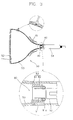
- the CRT includes a bulb 50 having a screen 52 coated with a fluorescent layer 51 and a conductive layer 53 coated on its inner surface, an electron gun 60 hermetically mounted in a neck portion 54 of the bulb 50, and a deflection yoke 70 mounted on a cone portion of the bulb 50.
- the electron gun 60 includes a final accelerating electrode 61 electrically connected to the conductive layer 53 and a focusing electrode 62 installed adjacent to the final accelerating electrode 61 and forming a main lens.
- leakage current shielding means within the neck portion 54 at the boundary between an area where the conductive layer 53 is coated and an area where the conductive layer 53 is not coated.
- the leakage current shielding means is for shielding leakage current flowing along the inner circumferential surface of the neck portion 54 due to a high voltage applied to the conductive layer 53.
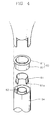
- the leakage current shielding means includes an annular fixing portion 81 fixed on the inner surface of the neck portion 54 and an inner glass 83 having a cylindrical supporting portion 82 spaced apart from the inner surface of the neck portion 54 and extended axially.
- the final accelerating electrode 61 of the electron gun is inserted into the supporting portion 82 to be supported.
- the neck portion 54 is cut and the fixing portion 81 is connected to the cutting portion so that the inner glass 83 is connected to the neck portion 54.
- a bent portion 61a bent outwardly is formed at the end of the focusing electrode side of the final accelerating electrode 61.
- the bent portion 61a is connected to the inner surface of the supporting portion 82.
- the conductive layer 53 is extended to the bent portion 61a of the final accelerating electrode 61 along the inner surface of the fixing portion 81 and supporting portion 82.
- the electrical connection between the conductive layer 53 and the final accelerating electrode 61 is not restricted to the above-described embodiment and may be attained by installing a separate conductive layer or a conductive member for connecting the conductive layer 53 and the final accelerating electrode 61.
- the leakage current shielding means may instead comprise an insulator (not shown) between the final accelerating electrode 61 and the inner surface of the neck portion 54.
- the insulator may have a cylindrical shape, and one end of the cylindrical insulator is fixed to one side of the neck portion 54.
- the electron beams emitted from the electron gun 60 is selectively deflected by a deflection yoke and scanned onto the fluorescent layer 51 to excite the phosphors, thereby forming an image. Also, excess therm ions landing on the phosphors are exhausted to the outside through the conductive layer to which a high voltage is applied and an anode port. During this process, the leaking current flowing along the inner surface of the neck portion due to a high voltage applied to the conductive layer is shielded by the inner glass 83.
- the current density of the electron beams emitted from the electron gun can be comparatively reduced. This improves the focusing characteristics of the electron gun, and prolongs the life of a fluorescent layer and the life of an electron emission source of the electron gun.
Landscapes
- Vessels, Lead-In Wires, Accessory Apparatuses For Cathode-Ray Tubes (AREA)
Applications Claiming Priority (2)
| Application Number | Priority Date | Filing Date | Title |
|---|---|---|---|
| KR9748553 | 1997-09-24 | ||
| KR1019970048553A KR19990026440A (ko) | 1997-09-24 | 1997-09-24 | 음극선관 |
Publications (1)
| Publication Number | Publication Date |
|---|---|
| EP0905741A1 true EP0905741A1 (de) | 1999-03-31 |
Family
ID=19521611
Family Applications (1)
| Application Number | Title | Priority Date | Filing Date |
|---|---|---|---|
| EP98307685A Withdrawn EP0905741A1 (de) | 1997-09-24 | 1998-09-22 | Kathodenstrahlröhre |
Country Status (4)
| Country | Link |
|---|---|
| US (1) | US6307315B1 (de) |
| EP (1) | EP0905741A1 (de) |
| JP (1) | JPH11144639A (de) |
| KR (1) | KR19990026440A (de) |
Citations (5)
| Publication number | Priority date | Publication date | Assignee | Title |
|---|---|---|---|---|
| CH220857A (de) * | 1940-12-06 | 1942-04-30 | Licentia Gmbh | Braunsche Röhre, bei der die Elektroden an einer aus isolierenden Stäben bestehenden gemeinsamen Halterung befestigt sind, zum Betrieb für hohe Spannungen. |
| US2509763A (en) * | 1947-04-09 | 1950-05-30 | Hartford Nat Bank & Trust Co | Electric discharge tube with directional electron beam |
| US3962599A (en) * | 1974-11-25 | 1976-06-08 | Gte Sylvania Incorporated | Shielding means for cathode ray tube |
| JPS60218746A (ja) * | 1984-04-12 | 1985-11-01 | Nec Corp | 陰極線管 |
| US4885503A (en) * | 1987-11-18 | 1989-12-05 | Hitachi, Ltd. | Color cathode-ray tube |
Family Cites Families (2)
| Publication number | Priority date | Publication date | Assignee | Title |
|---|---|---|---|---|
| US5202606A (en) * | 1989-06-23 | 1993-04-13 | U.S. Philips Corporation | Cathode-ray tube with focussing structure and getter means |
| KR200190103Y1 (ko) * | 1995-04-25 | 2000-08-01 | 김순택 | 음극선관용 전자총(electrol gun for cathode ray tube) |
-
1997
- 1997-09-24 KR KR1019970048553A patent/KR19990026440A/ko not_active Ceased
-
1998
- 1998-09-11 JP JP10257917A patent/JPH11144639A/ja not_active Withdrawn
- 1998-09-22 EP EP98307685A patent/EP0905741A1/de not_active Withdrawn
- 1998-09-22 US US09/158,196 patent/US6307315B1/en not_active Expired - Fee Related
Patent Citations (5)
| Publication number | Priority date | Publication date | Assignee | Title |
|---|---|---|---|---|
| CH220857A (de) * | 1940-12-06 | 1942-04-30 | Licentia Gmbh | Braunsche Röhre, bei der die Elektroden an einer aus isolierenden Stäben bestehenden gemeinsamen Halterung befestigt sind, zum Betrieb für hohe Spannungen. |
| US2509763A (en) * | 1947-04-09 | 1950-05-30 | Hartford Nat Bank & Trust Co | Electric discharge tube with directional electron beam |
| US3962599A (en) * | 1974-11-25 | 1976-06-08 | Gte Sylvania Incorporated | Shielding means for cathode ray tube |
| JPS60218746A (ja) * | 1984-04-12 | 1985-11-01 | Nec Corp | 陰極線管 |
| US4885503A (en) * | 1987-11-18 | 1989-12-05 | Hitachi, Ltd. | Color cathode-ray tube |
Non-Patent Citations (1)
| Title |
|---|
| PATENT ABSTRACTS OF JAPAN vol. 010, no. 069 (E - 389) 18 March 1986 (1986-03-18) * |
Also Published As
| Publication number | Publication date |
|---|---|
| KR19990026440A (ko) | 1999-04-15 |
| US6307315B1 (en) | 2001-10-23 |
| JPH11144639A (ja) | 1999-05-28 |
Similar Documents
| Publication | Publication Date | Title |
|---|---|---|
| US4564786A (en) | External neck charge dissipation means for an in-line color cathode ray tube | |
| US6307315B1 (en) | Cathode ray tube | |
| GB2115603A (en) | Cathode-ray tube | |
| US6456080B1 (en) | Cathode ray tube | |
| KR100243948B1 (ko) | 음극선관용 전자총 | |
| CA1117174A (en) | Electron gun shield cup having radial inward formations | |
| EP1575077A1 (de) | Widerstand für eine elektronenkanonenstruktur, elektronenkanonenstruktur und kathodenstrahlröhre | |
| US6362564B1 (en) | Color cathode ray tube with prescribed neck thickness | |
| US5202615A (en) | Arc suppressing means for cathode ray tube | |
| JP2553468B2 (ja) | 陰極線管における電子銃 | |
| US6744190B2 (en) | Cathode ray tube with modified in-line electron gun | |
| KR200276470Y1 (ko) | 칼라 브라운관의 전자총 | |
| KR200171929Y1 (ko) | 음극선관용전자총 | |
| KR100813830B1 (ko) | 음극선관용 전자총 | |
| WO2004019366A1 (ja) | 電子銃構体用抵抗器及び陰極線管 | |
| KR100294495B1 (ko) | 칼러 음극선관 | |
| KR950004391B1 (ko) | 브라운관의 전자총용 벌브스페이서 | |
| KR100649254B1 (ko) | 전자총 및 이를 구비한 음극선관 | |
| KR100331837B1 (ko) | 음극선관용 전자총 | |
| EP1017084A1 (de) | Farbbildröhre | |
| JPH0312423B2 (de) | ||
| KR20010095590A (ko) | 음극선관용 전자총 | |
| JPH11176348A (ja) | 電子銃構体及びこの電子銃構体を備えたカラー受像管 | |
| JP2002279914A (ja) | 管内用抵抗器並びに電子銃構体及び陰極線管 | |
| JPH11144649A (ja) | 陰極線管 |
Legal Events
| Date | Code | Title | Description |
|---|---|---|---|
| PUAI | Public reference made under article 153(3) epc to a published international application that has entered the european phase |
Free format text: ORIGINAL CODE: 0009012 |
|
| AK | Designated contracting states |
Kind code of ref document: A1 Designated state(s): DE FR GB NL |
|
| AX | Request for extension of the european patent |
Free format text: AL;LT;LV;MK;RO;SI |
|
| 17P | Request for examination filed |
Effective date: 19990623 |
|
| AKX | Designation fees paid |
Free format text: DE FR GB NL |
|
| 17Q | First examination report despatched |
Effective date: 20021121 |
|
| STAA | Information on the status of an ep patent application or granted ep patent |
Free format text: STATUS: THE APPLICATION IS DEEMED TO BE WITHDRAWN |
|
| 18D | Application deemed to be withdrawn |
Effective date: 20030401 |