EP0905744B1 - Lampe à halogénure métallique - Google Patents
Lampe à halogénure métallique Download PDFInfo
- Publication number
- EP0905744B1 EP0905744B1 EP98117447A EP98117447A EP0905744B1 EP 0905744 B1 EP0905744 B1 EP 0905744B1 EP 98117447 A EP98117447 A EP 98117447A EP 98117447 A EP98117447 A EP 98117447A EP 0905744 B1 EP0905744 B1 EP 0905744B1
- Authority
- EP
- European Patent Office
- Prior art keywords
- discharge tube
- lamp
- wall thickness
- metal halide
- cylindrical portion
- Prior art date
- Legal status (The legal status is an assumption and is not a legal conclusion. Google has not performed a legal analysis and makes no representation as to the accuracy of the status listed.)
- Expired - Lifetime
Links
Images


Classifications
-
- H—ELECTRICITY
- H01—ELECTRIC ELEMENTS
- H01J—ELECTRIC DISCHARGE TUBES OR DISCHARGE LAMPS
- H01J61/00—Gas-discharge or vapour-discharge lamps
- H01J61/82—Lamps with high-pressure unconstricted discharge having a cold pressure > 400 Torr
- H01J61/827—Metal halide arc lamps
-
- H—ELECTRICITY
- H01—ELECTRIC ELEMENTS
- H01J—ELECTRIC DISCHARGE TUBES OR DISCHARGE LAMPS
- H01J61/00—Gas-discharge or vapour-discharge lamps
- H01J61/02—Details
- H01J61/30—Vessels; Containers
- H01J61/302—Vessels; Containers characterised by the material of the vessel
Definitions
- the present invention relates to a metal halide lamp with a ceramic discharge tube.
- metal halide lamps comprising a ceramic discharge tube held within an outer tube
- metal halide lamps having a discharge tube at both end portions of a transparent alumina tube that are closed by insulating ceramic caps or conducting caps are known as such metal halide lamps (see Publication of Unexamined Japanese Patent Publication (Tokkai) No. Sho 62-283543).
- metal halide lamps having a ceramic discharge tube having end portions at both ends of a central portion and having a smaller diameter than the central portion (see Publication of Unexamined Japanese Patent Publication (Tokkai) No. Hei 6-196131). Electrically conductive lead-wires having an electrode at their ends are inserted at both end portions. The gaps between the edge portions of the discharge tube and the conductive lead-wire are sealed with a sealing material
- Such conventional metal halide lamps using ceramic discharge tubes utilize the high thermal resistance of the ceramic to raise the tube-wall load (lamp power per surface area of the entire discharge tube) compared to metal halide lamps having a quartz discharge tube. It is known that by maintaining a vacuum inside the outer tube, the discharge tube temperature can be raised and the lamp efficiency can be increased. However, there has been no detailed research about the lamp efficiency and lifetime and their relation to the volume of the transparent ceramic constituting the discharge tube.
- the discharge tube temperature is necessary to realize high efficiency and high color rendition.
- the discharge tube may be damaged due to heat-cycles during the lamp lifetime, because the discharge tube temperature is too high.
- the present invention has the following structure:
- a metal halide lamp comprises a discharge tube of transparent ceramic in which a discharge metal is sealed, the discharge tube having a main cylindrical portion, ring portions provided at both ends of the main cylindrical portion, and tubular cylindrical portions provided at the ring portions; and a pair of electrodes inside the discharge tube; wherein a wall thickness ⁇ (in mm) of the main cylindrical portion satisfies the relation 0.0023 ⁇ W + 0.22 ⁇ ⁇ ⁇ 0.0023 x W + 0.62, and a wall thickness ⁇ (in mm) of the ring portion satisfies the relation 0.0094 ⁇ W + 0.5 ⁇ ⁇ ⁇ 0.0094 ⁇ W + 1.5, wherein W is the lamp power expressed in Watt.
- metal halide lamps can be provided that have a stable lifetime and a lamp efficiency that is increased at least 15% compared to high-color-rendition high-performance metal halide lamps of various wattages using a quartz discharge tube.
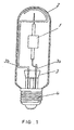
- the 70W metal halide lamp illustrated in Fig. 1 which is a first embodiment of the present invention, comprises a ceramic discharge tube 1, rigidly supported by metal wires 3a and 3b inside an outer tube 2.
- One end of the outer tube 2 is provided with a stem 3, which seals the outer tube 2 air-tight. A vacuum is maintained in the outer tube 2.
- a certain amount of mercury, argon as a noble gas for a starting gas, and iodides of dysprosium, thulium, holmium, thallium, and sodium as metal halides are sealed in the discharge tube 1.
- Numeral 4 indicates a lamp base.
- the ceramic discharge tube 1 has an outer diameter of 7.8mm and comprises tubular cylindrical portions 6 of 2.6mm external diameter and 0.8mm internal diameter, on both sides of a main cylindrical portion 5 having a wall thickness ⁇ (in mm) of 0.6mm.
- the main cylindrical portion 5 and the tubular cylindrical portions 6 are sintered into one piece with ring portions 7 having a wall thickness ⁇ (in mm) of 1.7mm.
- Lead-in wires 9 made of niobium with a 0.7mm diameter having an electrode 8 at the tip are inserted into the tubular cylindrical portions 6.
- the lead-in wires 9 are sealed with a sealing material 10 in the tubular cylindrical portion 6, so that the electrodes 8 are positioned inside the main cylindrical portion 5, and sealing portions 11 are formed in the tubular cylindrical portion 6.
- Numeral 12 indicates a mercury pellet and numeral 13 a iodide pellet.
- the lamp efficiency was examined for changing wall thickness ⁇ (in mm) of the main cylindrical portion 5 and changing wall thickness ⁇ (in mm) of the ring portions 7, and the occurrence of leaks in the discharge tube was examined after 100 hours use.
- occurrence of leaks in the discharge tube means the number of lamps out of a number of eight lamps in which cracks occur in the discharge tube due to the heat cycle of the discharge tube when the lamp is operating, which leads to burn-out of the lamp.
- the criterion for the lamp efficiency was whether the performance of a conventional high-performance metal halide lamp with high color rendition (at least Ra80) using a quartz discharge tube could be increased at least 15%. This criterion is 90 lm/W for a 70W metal halide lamp.
- Table 1 shows the results of these measurements.
- ⁇ (in mm) ⁇ (in mm) Lamp Efficiency (lm/W) Occurrence of Leaks in the Discharge Tube Evaluation 0.3 1.2 106 4 / 8 ⁇ 0.3 1.7 104 3 / 8 ⁇ 0.3 2.2 102 1 / 8 ⁇ 0.4 1.0 104 1 / 8 ⁇ 0.4 1.2 102 0 / 8 ⁇ 0.4 1.7 98 0 / 8 ⁇ 0.4 2.2 95 0 / 8 ⁇ 0.4 2.6 89 0 / 8 ⁇ 0.5 1.7 95 0 / 8 ⁇ 0.6 1.7 94 0 / 8 ⁇ 0.7 1.7 93 0 / 8 ⁇ 0.8 1.7 92 0 / 8 ⁇ 0.8 2.2 90 0 / 8 ⁇ 0.9 2.2 89 0 / 8 ⁇ 0.9 2.6 87 0 / 8 ⁇
- the tube-wall load was held constant at 30W/cm 2 .
- the lamps marked with a circle (O) in the "Evaluation" column of Table 1 are 70W metal halide lamps with a stable lifetime and considerably increased lamp efficiency.
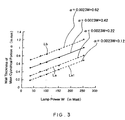
- Each of the different lamps had a stable lifetime with a lamp efficiency that was increased at least 15% compared to a high-color-rendition high-performance metal halide lamp using a quartz discharge tube when the wall thickness ⁇ (in mm) of the main cylindrical portion 5 was in the range between the straight lines La and Lb as indicated in Fig. 3.
- the lamp efficiency did not improve at least 15% compared to conventional metal halide lamps using a quartz discharge tube.
- a metal halide lamp that has a stable lifetime with a lamp efficiency that is increased at least 15% compared to a high color-rendition high-performance metal halide lamp using a quartz discharge tube can be obtained, when the wall thickness ⁇ (in mm) is in the range of 0.0023 ⁇ W + 0.22 ⁇ ⁇ ⁇ 0.0023 ⁇ W + 0.62 and the wall thickness ⁇ (in mm) of the ring portions 7 is in the range of 0.0094 ⁇ W + 0.5 ⁇ ⁇ ⁇ 0.0094 ⁇ W + 1.5, wherein W is the lamp power in Watt.
- the 70W metal halide lamp according to a second embodiment of the present invention, comprises a ceramic discharge tube 1, rigidly supported by metal wires 3a and 3b inside an outer tube 2, as illustrated in Fig. 1.
- One end of the outer tube 2 is provided with a stem 3, which seals the outer tube 2 air-tight.
- the outer tube 2 is filled with nitrogen under a pressure of 466 mbar (350 Torr.)
- a certain amount of mercury, argon as a noble gas for a starting gas, and iodides of dysprosium, thulium, holmium, thallium, and sodium as metal halides are sealed in the discharge tube 1.
- Numeral 4 indicates a lamp base.
- the ceramic discharge tube 1 has an outer diameter of 7.6mm and comprises tubular cylindrical portions 6 of 2.6mm external diameter and 0.8mm internal diameter, on both sides of a main cylindrical portion 5 with a wall thickness ⁇ (in mm) of 0.5mm.
- the main cylindrical portion 5 and the tubular cylindrical portions 6 are sintered into one piece with ring portions 7 with a wall thickness ⁇ (in mm) of 1.5mm.
- the other structure is same as in the first embodiment.
- the lamp efficiency was examined for a changing wall thickness ⁇ (in mm) of the main cylindrical portion 5 and a changing wall thickness ⁇ (in mm) of the ring portions 7, and the occurrence of leaks in the discharge tube was examined after 100 hours use.
- Table 2 shows the results of these measurements.
- ⁇ (in mm) ⁇ (in mm) Lamp Efficiency (lm/W) Occurrence of Leaks in the Discharge Tube Evaluation 0.2 1.0 110 5 / 8 ⁇ 0.2 1.2 108 4 / 8 ⁇ 0.2 1.7 106 4 / 8 ⁇ 0.2 2.2 104 3 / 8 ⁇ 0.3 0.8 110 2 / 8 ⁇ 0.3 1.0 108 0 / 8 ⁇ 0.3 1.2 106 0 / 8 ⁇ 0.3 1.7 104 0 / 8 ⁇ 0.3 2.2 102 0 / 8 ⁇ 0.4 1.0 104 0 / 8 ⁇ 0.4 1.2 102 0 / 8 ⁇ 0.4 1.7 98 0 / 8 ⁇ 0.4 2.2 95 0 / 8 ⁇ 0.4 2.6 89 0 / 8 ⁇ 0.5 1.7 95 0 / 8 ⁇ 0.6 1.7 94 0 / 8 ⁇ 0.7 93 0
- the lamps marked with a circle (O) in the "Evaluation" column of Table 2 are lamps with a stable lifetime and a lamp efficiency that is increased at least 15% compared to conventional metal halide lamps using a quartz discharge tube.
- Deterioration of the lamp efficiency does not occur due to the very high vapor pressure of the metal halides in the discharge tube and the lower temperature of the discharge tube.
- Each of the different lamps had a stable lifetime with a lamp efficiency that was increased at least 15% compared to a high-color-rendition high-performance metal halide lamp using a quartz discharge tube when the wall thickness ⁇ (in mm) of the main cylindrical portion 5 was in the range between the straight lines La1 and Lb as indicated in Fig. 3.
- the lamp efficiency did not improve at least 15% compared to conventional metal halide lamps using a quartz discharge tube.
- a metal halide lamp that has a stable lifetime with a lamp efficiency that is increased at least 15% compared to a high-color-rendition high-performance metal halide lamp using a quartz discharge tube can be obtained when the wall thickness ⁇ (in mm) is in the range of 0.0023 ⁇ W + 0.12 ⁇ ⁇ ⁇ 0.0023 ⁇ W + 0.62 and the wall thickness ⁇ (in mm) of the ring portions 7 is in the range of 0.0094 ⁇ W + 0.3 ⁇ ⁇ ⁇ 0.0094 ⁇ W + 1.5, wherein W is the lamp power in Watt.
- niobium wires were used for the lead-in wires in the sealed portion.
- other materials with a thermal expansion coefficient that is close to the thermal expansion coefficient of the discharge tube material can be used for the lead-in wires.
- conductive or non-conductive ceramic caps can be used for the sealing portion.
- a discharge tube can be used where the main cylindrical portion, the tubular cylindrical portions and the ring portions are molded in one piece.
- the outer tube 2 was filled with nitrogen gas, but it can also be filled with a gas mixture containing nitrogen.
- a gas that can be mixed with nitrogen and then filled into the outer tube 2 is neon (Ne). If a gas mixture containing nitrogen is used, it is preferable that the nitrogen gas accounts for at least 50vol% of the gas mixture.
- the ceramic material used for the discharge tube there is no particular limitation concerning the ceramic material used for the discharge tube.
- single chrystal metallic oxides such as sapphire, polychrystal metallic oxides such as alumina (Al 2 O 3 ), yttrium-aluminium-garnet (YAG), and yttriumoxide (YOX), or polychrystal nonoxides such as aluminium nitrides (AlX) can be used for the discharge tube.
- hard glass has been used for the outer tube in the first and the second embodiment.
- outer tube in the present invention there is no particular limitation concerning the outer tube in the present invention, and any known material for such outer tubes can be used.
Landscapes
- Vessels And Coating Films For Discharge Lamps (AREA)
- Discharge Lamps And Accessories Thereof (AREA)
Claims (2)
- Lampe à halogénure métallique comprenant :caractérisé en ce queun tube à décharge (1) en céramique transparente dans lequel un métal de décharge est scellé, ledit tube à décharge (1) possédant une partie principale cylindrique (5), des parties annulaires (7) placées aux deux extrémités de la partie principale cylindrique (5), et des parties cylindriques tubulaires (6) placées sur les parties annulaires (7) ; etune paire d'électrodes (8) à l'intérieur du tube à décharge (1) ;
l'épaisseur de paroi α (en mm) de ladite partie principale cylindrique (5) satisfait à la relation - Lampe à halogénure métallique comprenant :caractérisé en ce queun tube extérieur rempli (2) d'un gaz comprenant de l'azote ;un tube à décharge (1) en céramique transparente dans lequel un métal de décharge est scellé, ledit tube à décharge (1) étant porté de manière étanche à l'air à l'intérieur dudic tube extérieur (2) et ledit tube de décharge (1) possédant une partie principale cylindrique (5), des parties annulaires (7) placées aux deux extrémités de la partie principale cylindrique (5), et des parties cylindriques tubulaires (6) placées sur les parties annulaires (7) ; etune paire d'électrodes (8) à l'intérieur du tube à décharge (1) ;
l'épaisseur de paroi α (en mm) de ladite partie principale cylindrique (5) satisfait à la relation
Applications Claiming Priority (3)
| Application Number | Priority Date | Filing Date | Title |
|---|---|---|---|
| JP261682/97 | 1997-09-26 | ||
| JP26168297 | 1997-09-26 | ||
| JP26168297 | 1997-09-26 |
Publications (3)
| Publication Number | Publication Date |
|---|---|
| EP0905744A2 EP0905744A2 (fr) | 1999-03-31 |
| EP0905744A3 EP0905744A3 (fr) | 1999-06-16 |
| EP0905744B1 true EP0905744B1 (fr) | 2003-07-16 |
Family
ID=17365271
Family Applications (1)
| Application Number | Title | Priority Date | Filing Date |
|---|---|---|---|
| EP98117447A Expired - Lifetime EP0905744B1 (fr) | 1997-09-26 | 1998-09-15 | Lampe à halogénure métallique |
Country Status (4)
| Country | Link |
|---|---|
| US (1) | US6137229A (fr) |
| EP (1) | EP0905744B1 (fr) |
| CN (1) | CN1134821C (fr) |
| DE (1) | DE69816390T2 (fr) |
Families Citing this family (15)
| Publication number | Priority date | Publication date | Assignee | Title |
|---|---|---|---|---|
| JP3676676B2 (ja) * | 1998-05-27 | 2005-07-27 | 日本碍子株式会社 | 高圧放電灯用の発光容器の製造方法 |
| EP1160831B1 (fr) * | 2000-05-30 | 2003-08-06 | Japan Storage Battery Co., Ltd. | Lampe à décharge |
| JP2002075272A (ja) * | 2000-08-29 | 2002-03-15 | Matsushita Electric Ind Co Ltd | メタルハライドランプ |
| JP2002334653A (ja) * | 2001-02-09 | 2002-11-22 | Matsushita Electric Ind Co Ltd | 発光管の製造方法及びそれに用いられる中子 |
| EP1271614B1 (fr) | 2001-06-27 | 2005-09-21 | Matsushita Electric Industrial Co., Ltd. | Lampe à halogénure métallique |
| JP2003016998A (ja) | 2001-06-28 | 2003-01-17 | Matsushita Electric Ind Co Ltd | メタルハライドランプ |
| JP3990582B2 (ja) * | 2001-06-29 | 2007-10-17 | 松下電器産業株式会社 | メタルハライドランプ |
| WO2003030212A1 (fr) * | 2001-10-02 | 2003-04-10 | Gem Lighting Llc | Lampe a decharge a haute intensite a enveloppe en saphir monocristallin |
| US20050168148A1 (en) * | 2004-01-30 | 2005-08-04 | General Electric Company | Optical control of light in ceramic arctubes |
| WO2006001166A1 (fr) * | 2004-06-29 | 2006-01-05 | Matsushita Electric Industrial Co., Ltd. | Lampe halogène métallique et appareil d’éclairage utilisant ladite lampe |
| US7682547B2 (en) * | 2004-10-26 | 2010-03-23 | General Electric Company | Integrally formed molded parts and method for making the same |
| US7473086B2 (en) * | 2004-12-01 | 2009-01-06 | General Electric Company | Porous mold insert and molds |
| US7279838B2 (en) * | 2005-03-09 | 2007-10-09 | General Electric Company | Discharge tubes |
| US7211954B2 (en) * | 2005-03-09 | 2007-05-01 | General Electric Company | Discharge tubes |
| US7474057B2 (en) * | 2005-11-29 | 2009-01-06 | General Electric Company | High mercury density ceramic metal halide lamp |
Citations (1)
| Publication number | Priority date | Publication date | Assignee | Title |
|---|---|---|---|---|
| US5424609A (en) * | 1992-09-08 | 1995-06-13 | U.S. Philips Corporation | High-pressure discharge lamp |
Family Cites Families (7)
| Publication number | Priority date | Publication date | Assignee | Title |
|---|---|---|---|---|
| US4734612A (en) * | 1985-07-15 | 1988-03-29 | Kabushiki Kaisha Toshiba | High pressure metal vapor discharge lamp |
| NL8502509A (nl) * | 1985-09-13 | 1987-04-01 | Philips Nv | Hogedrukkwikdampontladingslamp. |
| DE3638857A1 (de) * | 1985-11-15 | 1987-05-21 | Toshiba Kawasaki Kk | Hochdruckentladungslampe |
| JPS62283543A (ja) * | 1986-05-31 | 1987-12-09 | Iwasaki Electric Co Ltd | 金属蒸気放電灯 |
| EP0587238B1 (fr) * | 1992-09-08 | 2000-07-19 | Koninklijke Philips Electronics N.V. | Lampe à décharge à haute pression |
| JP3627370B2 (ja) * | 1996-04-11 | 2005-03-09 | 日本電池株式会社 | セラミック放電灯 |
| DE19645960A1 (de) * | 1996-11-07 | 1998-05-14 | Patent Treuhand Ges Fuer Elektrische Gluehlampen Mbh | Keramisches Entladungsgefäß |
-
1998
- 1998-08-27 US US09/140,974 patent/US6137229A/en not_active Expired - Lifetime
- 1998-09-15 EP EP98117447A patent/EP0905744B1/fr not_active Expired - Lifetime
- 1998-09-15 DE DE69816390T patent/DE69816390T2/de not_active Expired - Lifetime
- 1998-09-25 CN CNB981207421A patent/CN1134821C/zh not_active Expired - Fee Related
Patent Citations (1)
| Publication number | Priority date | Publication date | Assignee | Title |
|---|---|---|---|---|
| US5424609A (en) * | 1992-09-08 | 1995-06-13 | U.S. Philips Corporation | High-pressure discharge lamp |
Also Published As
| Publication number | Publication date |
|---|---|
| DE69816390T2 (de) | 2004-06-09 |
| CN1213155A (zh) | 1999-04-07 |
| DE69816390D1 (de) | 2003-08-21 |
| CN1134821C (zh) | 2004-01-14 |
| US6137229A (en) | 2000-10-24 |
| EP0905744A2 (fr) | 1999-03-31 |
| EP0905744A3 (fr) | 1999-06-16 |
Similar Documents
| Publication | Publication Date | Title |
|---|---|---|
| US6861805B2 (en) | Coil antenna/protection for ceramic metal halide lamps | |
| JP3825009B2 (ja) | メタルハライドランプ | |
| US6137229A (en) | Metal halide lamp with specific dimension of the discharge tube | |
| JP2010192464A (ja) | 高圧放電ランプ | |
| US7057350B2 (en) | Metal halide lamp with improved lumen value maintenance | |
| EP1058288B1 (fr) | Lampe à décharge à vapeur métallique | |
| US6492764B2 (en) | Metal halide lamp | |
| JP2004528694A (ja) | セラミックメタルハライドランプ | |
| EP1306884B1 (fr) | Lampe à décharge à haute pression | |
| JP5010919B2 (ja) | 放電ランプ | |
| EP2476133B1 (fr) | Lampe à décharge à haute intensité | |
| JP2009032446A (ja) | 高圧放電ランプ | |
| EP1056116B1 (fr) | Electrode pour une lampe à halogénure métallique | |
| JP3271946B2 (ja) | メタルハライドランプ | |
| JP2003059451A (ja) | 高圧放電ランプ | |
| EP1793411A2 (fr) | Lampe de décharge haute pression | |
| JP2007080768A (ja) | メタルハライドランプおよび照明装置 |
Legal Events
| Date | Code | Title | Description |
|---|---|---|---|
| PUAI | Public reference made under article 153(3) epc to a published international application that has entered the european phase |
Free format text: ORIGINAL CODE: 0009012 |
|
| AK | Designated contracting states |
Kind code of ref document: A2 Designated state(s): DE NL |
|
| AX | Request for extension of the european patent |
Free format text: AL;LT;LV;MK;RO;SI |
|
| RIN1 | Information on inventor provided before grant (corrected) |
Inventor name: YAMAMOTO, TAKASHI Inventor name: NAKAYAMA, SHIKI Inventor name: SUGIMOTO, KOUICHI Inventor name: NOHARA, HIROSHI Inventor name: TAKEDA, KAZUO Inventor name: NISHIURA, YOSHIHARU |
|
| PUAL | Search report despatched |
Free format text: ORIGINAL CODE: 0009013 |
|
| AK | Designated contracting states |
Kind code of ref document: A3 Designated state(s): AT BE CH CY DE DK ES FI FR GB GR IE IT LI LU MC NL PT SE |
|
| AX | Request for extension of the european patent |
Free format text: AL;LT;LV;MK;RO;SI |
|
| 17P | Request for examination filed |
Effective date: 19990814 |
|
| AKX | Designation fees paid |
Free format text: DE NL |
|
| RAP1 | Party data changed (applicant data changed or rights of an application transferred) |
Owner name: MATSUSHITA ELECTRIC INDUSTRIAL CO., LTD. |
|
| 17Q | First examination report despatched |
Effective date: 20020521 |
|
| GRAH | Despatch of communication of intention to grant a patent |
Free format text: ORIGINAL CODE: EPIDOS IGRA |
|
| GRAH | Despatch of communication of intention to grant a patent |
Free format text: ORIGINAL CODE: EPIDOS IGRA |
|
| RIN1 | Information on inventor provided before grant (corrected) |
Inventor name: YAMAMOTO, TAKASHI Inventor name: NAKAYAMA, SHIKI Inventor name: SUGIMOTO, KOUICHI Inventor name: NOHARA, HIROSHI Inventor name: TAKEDA, KAZUO Inventor name: NISHIURA, YOSHIHARU |
|
| GRAH | Despatch of communication of intention to grant a patent |
Free format text: ORIGINAL CODE: EPIDOS IGRA |
|
| GRAA | (expected) grant |
Free format text: ORIGINAL CODE: 0009210 |
|
| AK | Designated contracting states |
Designated state(s): DE NL |
|
| REF | Corresponds to: |
Ref document number: 69816390 Country of ref document: DE Date of ref document: 20030821 Kind code of ref document: P |
|
| PLBE | No opposition filed within time limit |
Free format text: ORIGINAL CODE: 0009261 |
|
| STAA | Information on the status of an ep patent application or granted ep patent |
Free format text: STATUS: NO OPPOSITION FILED WITHIN TIME LIMIT |
|
| 26N | No opposition filed |
Effective date: 20040419 |
|
| PGFP | Annual fee paid to national office [announced via postgrant information from national office to epo] |
Ref country code: NL Payment date: 20140809 Year of fee payment: 17 Ref country code: DE Payment date: 20140911 Year of fee payment: 17 |
|
| REG | Reference to a national code |
Ref country code: DE Ref legal event code: R119 Ref document number: 69816390 Country of ref document: DE |
|
| REG | Reference to a national code |
Ref country code: NL Ref legal event code: MM Effective date: 20151001 |
|
| PG25 | Lapsed in a contracting state [announced via postgrant information from national office to epo] |
Ref country code: DE Free format text: LAPSE BECAUSE OF NON-PAYMENT OF DUE FEES Effective date: 20160401 |
|
| PG25 | Lapsed in a contracting state [announced via postgrant information from national office to epo] |
Ref country code: NL Free format text: LAPSE BECAUSE OF NON-PAYMENT OF DUE FEES Effective date: 20151001 |