EP0905865A2 - Methode zur Montage des Antriebsmotors einer Magnetplatteneinheit - Google Patents
Methode zur Montage des Antriebsmotors einer Magnetplatteneinheit Download PDFInfo
- Publication number
- EP0905865A2 EP0905865A2 EP98307833A EP98307833A EP0905865A2 EP 0905865 A2 EP0905865 A2 EP 0905865A2 EP 98307833 A EP98307833 A EP 98307833A EP 98307833 A EP98307833 A EP 98307833A EP 0905865 A2 EP0905865 A2 EP 0905865A2
- Authority
- EP
- European Patent Office
- Prior art keywords
- flange
- support shaft
- support
- fixing
- pillar
- Prior art date
- Legal status (The legal status is an assumption and is not a legal conclusion. Google has not performed a legal analysis and makes no representation as to the accuracy of the status listed.)
- Granted
Links
Images


Classifications
-
- H—ELECTRICITY
- H02—GENERATION; CONVERSION OR DISTRIBUTION OF ELECTRIC POWER
- H02K—DYNAMO-ELECTRIC MACHINES
- H02K15/00—Processes or apparatus specially adapted for manufacturing, assembling, maintaining or repairing of dynamo-electric machines
- H02K15/14—Casings; Enclosures; Supports
Definitions
- the present invention relates to a method of assembling a magnetic disk driving motor.
- This magnetic disk driving motor is, in a motor for driving magnetic disk including, as shown in FIG. 4, a fixing frame 1b, a center shaft 47 set up on the fixing frame 1b, a pair of bearings 37 and 38 fitted over the large-diametrical portion 49 of the center shaft 47 with a predetermined distance apart from each other, a rotor frame 12a in a cup form fitted over the pair of bearings 37 and 38, a permanent magnet 45 mounted on the rotor frame 12a, laminated cores 6 constituting armatures 5, and armature coils 21 wound around the laminated cores 6, characterised by that the fixing frame 1b is provided with a center axial pipe 2b, the small.
- the diametrical portion 48 of the center shaft 47 is put inside the free end portion of the center axial pipe 2b, the laminated core 6 is fitted over the outer peripheral face of the center axial pipe 2b, a hole 35 is made in the fixing frame 1b, and a lead wire 23 from the armature coil 21 is led out through the hole 35, whereas the rotor frame 12a has a cylindrical wall 43, which is provided with a disk supporting table 15 for mounting a magnetic disk such that the magnetic disk is mounted around the cylindrical wall 43.
- reference numeral 29 denotes a flange
- 32 denotes a large-diametrical portion formed at the base portion of the center axial pipe 2b
- 33 denotes a medium-diametrical portion contiguous to the large-diametrical portion 32
- 34 denotes a printed board.
- the rotor frame 12a borne by the pair of bearings 37 and 38 for rotation is held in a cantilevered manner on the center shaft 47 mounted on the center axial pipe 2b having the armatures 5 fixed thereon. Therefore, though the side wall 43 of the rotor frame 12a is extended so as to cover the outer periphery of the armature 5, it is enabled to make accurate concentric rotation not swaying with respect to the armature 5. Accordingly, the magnetic disk set on the rotor frame 12a can make accurate rotation free from irregularities such as swaying.
- the motor is not provided with end plates surrounding the armature 5 on the side of the fixing frame 1b, the number of the components can be decreased and it is made possible to lead out the coil lead wire 23 through the hole 35 made in the fixing frame 1b and, hence, the structure of the whole of the motor can be greatly simplified.
- the armature 5 is fixed on the outer peripheral face of the center axial pipe 2b on which the center shaft 47 is mounted, such an effect is stated to be obtained that stress is applied radially and inwardly toward the center axial pipe 2b by the installation of the armature 5 so that the small-diametrical portion 48 of the center shaft 47 is compressed and, thereby, the center shaft 47 is fixed more securely to the center axial pipe 2b.
- the present invention was made to overcome the above mentioned difficulties included in the prior art. It is an object of the invention to provide such a method of assembling a magnetic disk driving motor, which is a magnetic disk driving motor adapted to prevent vibration noise of the driving motor from being transmitted to the magnetic disk device, that keeps the rotating center shaft of the rotor from deviating from its right position during the assembling work.
- the invention provides such a method of fabricating a magnetic disk driving motor, in a method of fabricating magnetic disk driving motor having a stator for generating a revolving magnetic field, exciting magnetic poles formed of a permanent magnet disposed around the stator in confronting relationship therewith, and a rotor frame in a cup form having the exciting magnetic poles on the inside of its lower end, held on the center shaft in a cantilevered manner, and supporting the magnetic disk, comprises the steps of holding, prior to fixing a laminated core in a flange, the flange at higher temperature than a support shaft, inserting, while the condition in the above described step is existing, the small-diametrical portion of the support shaft into a through hole made in a support pillar projected from the flange integrally therewith thereby fixing the support shaft in the through hole made in the support pillar projected from the flange, and fixing, after fixing the support shaft in the support pillar on the flange, the laminated core
- the flange In inserting the small-diametrical portion of the support shaft into the through hole made in the support pillar, the flange is held at higher temperature than the support shaft by keeping the support shaft at the normal temperature and heating the flange, the flange is held at higher temperature than the support shaft by cooling the support shaft and heating the flange, or the flange is held at higher temperature than the support shaft by cooling the support shaft and keeping the flange at the normal temperature.
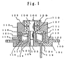
- FIG. 1 is a sectional view of an embodiment of the invention.
- FIG. 2 is a drawing explanatory of shrink fitting operation of a support shaft.
- FIG. 3 is a drawing explanatory of shrink fitting operation of a support shaft.
- FIG. 4 is a sectional view of a prior art example.
- FIG. 1 is a sectional view of the same.
- the magnetic disk driving motor according to the invention has a flange 100 made of a metal such as aluminum, and in the center of the flange 100, there is provided a dish-formed recess 101.
- Reference numeral 102 denotes a fixing hole for fixing the flange in place.
- a pillar 104 having a step portion 103 and serving as a center shaft.
- a small-diametrical portion 107 of a support shaft 106 is securely fixed by shrink fitting.
- the diameter d1 of the small-diametrical portion 107 of the support shaft 106 is made slightly larger than the inner diameter d2 of the through hole 105 made in the support pillar 104.
- the whole of the flange 100 made of aluminum is heated up to around 200 degrees C. By this heating up, the flange as a whole expands so that the inner diameter d2 of the through hole 105 is expanded a little and becomes greater than the diameter d1 of the small-diametrical portion 107.
- the support shaft 106 made of steel is cooled down to around - 10 degrees C. by a cooling device.
- the diameter d1 of the small-diametrical portion 107 becomes smaller than the inner diameter d2 of the through hole 105.
- the small-diametrical portion 107 is quickly inserted into the through hole 105 as shown in FIG. 3 while they are held in the condition d2 > d1.
- the diameter of the small-diametrical portion of the support shaft 106 becomes larger to restore its original dimension and the inner diameter of the through hole 105 shrinks so that the support shaft 106 is securely fixed in the support pillar 104.
- an impulse by drive fitting or a large stress by press fitting as with the prior art is not given to the support pillar 104. Therefore, even if the support pillar is made of such a soft metal as aluminum, it is prevented from deforming and the support shaft 106 after being fitted maintains its positional accuracy.
- holding the flange at around 200 degrees C. and the support shaft at around - 10 degrees C is an example and it is well if a temperature difference is produced between both the members such that the condition d2 > d1 exists.
- a rotor cup 111 over the large-diametrical portion 108 of the support shaft 106, there are fitted two ball bearings 109 and 110 spaced apart a little from each other. Further, over the outer rings of the ball bearings 109 and 110, there is rotatably fitted a rotor cup 111. The lower end of the rotor cup 111 is extended downward to reach the bottom of the recess 101. On the peripheral wall 112 of the rotor cup 111 close to its lower end, there is provided a disk supporting table 113.
- FIG. 1 On the inner side of the peripheral wall 112, there is fixed a cylindrical permanent magnet 114 forming the exciting magnetic poles. On the inner side of the permanent magnet 114, there are provided stators 116 witha small gap 115 apart from the permanent magnet.
- the stator 116 has a laminated core 117 provided with a magnetic pole at its front end and an armature coil 118 wound around the same. The lead wire 119 of the armature coil 118 is led out through a hole 120 made in the recess 101.
- the lower end face of the laminated core 117 is accurately positioned on the step portion 103 provided in the center of the recess 101 and securely fixed thereto with an adhesive agent or the like.
- a noise cutoff layer 121 is interposed between the inner side of the laminated core 117 and the pillar 104.
- the noise cutoff layer 121 is provided by an air gap.
- the noise cutoff layer 121 provided by air gap has an extremely high acoustic impedance. It also has an extremely high acoustic impedance when seen from the side of the pillar 104 made of a metal.
- Reference numeral 122 denotes a belleville spring interposed between the ball bearings 109 and 110.
- the above noise cutoff layer 121 need not necessarily be an air gap but may be such a substance as porous ceramic or porous synthetic resin filled therein, which has a high acoustic impedance when seen from the side of the laminated core 117 or the pillar 104.
- the present invention in a method of fabricating a magnetic disk driving motor having a stator for generating a revolving magnetic field, exciting magnetic poles formed of a permanent magnet disposed around the stator in confronting relationship therewith, and a rotor frame having the exciting magnetic poles on the inner side of its lower end, rotatably held on a center shaft in a cantilevered manner, and supporting a magnetic disk, comprises the steps of holding, prior to fixing a laminated core in a flange, the flange at higher temperature than a support shaft, inserting, while the condition in the above described step is existing, the small-diametrical portion of the support shaft into a through hole made in a support pillar projected from the flange integrally therewith thereby fixing the support shaft in the through hole made in the support pillar projected from the flange, and fixing, after fixing the support shaft in the support pillar on the flange, the laminated core in the flange with a distance apart from the support pillar
Landscapes
- Engineering & Computer Science (AREA)
- Manufacturing & Machinery (AREA)
- Power Engineering (AREA)
- Manufacture Of Motors, Generators (AREA)
- Brushless Motors (AREA)
- Iron Core Of Rotating Electric Machines (AREA)
- Permanent Magnet Type Synchronous Machine (AREA)
- Rotational Drive Of Disk (AREA)
- Connection Of Motors, Electrical Generators, Mechanical Devices, And The Like (AREA)
Applications Claiming Priority (3)
| Application Number | Priority Date | Filing Date | Title |
|---|---|---|---|
| JP26208097 | 1997-09-26 | ||
| JP9262080A JPH1198773A (ja) | 1997-09-26 | 1997-09-26 | 磁気ディスク駆動用モータの製造方法 |
| JP262080/97 | 1997-09-26 |
Publications (3)
| Publication Number | Publication Date |
|---|---|
| EP0905865A2 true EP0905865A2 (de) | 1999-03-31 |
| EP0905865A3 EP0905865A3 (de) | 1999-12-29 |
| EP0905865B1 EP0905865B1 (de) | 2006-12-20 |
Family
ID=17370758
Family Applications (1)
| Application Number | Title | Priority Date | Filing Date |
|---|---|---|---|
| EP19980307833 Expired - Lifetime EP0905865B1 (de) | 1997-09-26 | 1998-09-25 | Methode zur Montage des Antriebsmotors einer Magnetplatteneinheit |
Country Status (3)
| Country | Link |
|---|---|
| EP (1) | EP0905865B1 (de) |
| JP (1) | JPH1198773A (de) |
| DE (1) | DE69836666D1 (de) |
Cited By (1)
| Publication number | Priority date | Publication date | Assignee | Title |
|---|---|---|---|---|
| DE102008058433B4 (de) | 2007-12-13 | 2018-03-22 | Asmo Co., Ltd. | Bürstenloser Motor und Herstellungsverfahren desselben |
Families Citing this family (2)
| Publication number | Priority date | Publication date | Assignee | Title |
|---|---|---|---|---|
| JP4372453B2 (ja) * | 2003-05-20 | 2009-11-25 | シナノケンシ株式会社 | モータの回転子の組立体の組立方法 |
| CN218102824U (zh) * | 2022-08-15 | 2022-12-20 | 广东美的环境电器制造有限公司 | 电机及具有该电机的风扇 |
Family Cites Families (4)
| Publication number | Priority date | Publication date | Assignee | Title |
|---|---|---|---|---|
| JPS5917019A (ja) * | 1982-07-20 | 1984-01-28 | Toshiba Corp | 回転体支持装置 |
| US4814652A (en) * | 1987-02-27 | 1989-03-21 | Maxtor Corporation | Disk drive motor with thermally matched parts |
| JP2590334B2 (ja) * | 1987-05-08 | 1997-03-12 | 長野日本電産 株式会社 | カップ形ロ−タを有する磁気ディスク駆動用モ−タ |
| US5097164A (en) * | 1988-12-29 | 1992-03-17 | Canon Kabushiki Kaisha | Hermetically sealed type dynamic pressure fluid bearing motor |
-
1997
- 1997-09-26 JP JP9262080A patent/JPH1198773A/ja active Pending
-
1998
- 1998-09-25 EP EP19980307833 patent/EP0905865B1/de not_active Expired - Lifetime
- 1998-09-25 DE DE69836666T patent/DE69836666D1/de not_active Expired - Lifetime
Cited By (2)
| Publication number | Priority date | Publication date | Assignee | Title |
|---|---|---|---|---|
| DE102008058433B4 (de) | 2007-12-13 | 2018-03-22 | Asmo Co., Ltd. | Bürstenloser Motor und Herstellungsverfahren desselben |
| DE102008058433B8 (de) * | 2007-12-13 | 2018-05-30 | Asmo Co., Ltd. | Bürstenloser Motor und Herstellungsverfahren desselben |
Also Published As
| Publication number | Publication date |
|---|---|
| JPH1198773A (ja) | 1999-04-09 |
| EP0905865B1 (de) | 2006-12-20 |
| DE69836666D1 (de) | 2007-02-01 |
| EP0905865A3 (de) | 1999-12-29 |
Similar Documents
| Publication | Publication Date | Title |
|---|---|---|
| US7626305B2 (en) | Armature, motor using the armature, and disk drive device using the motor | |
| US9065315B1 (en) | Motor and disk drive apparatus | |
| US8137079B2 (en) | Motor, fan and manufacturing method of the same | |
| JP2002136031A (ja) | ブラシレスモータ及びその製造方法 | |
| US8599517B1 (en) | Spindle motor and disk drive apparatus | |
| US8737017B1 (en) | Spindle motor and disk drive apparatus | |
| US10177625B2 (en) | Motor | |
| US6614139B2 (en) | Motor having a dynamic pressure bearing apparatus and a manufacturing method thereof | |
| CN108933496B (zh) | 马达 | |
| EP0911943B1 (de) | Motor für Magnetplattenantrieb | |
| EP0905865B1 (de) | Methode zur Montage des Antriebsmotors einer Magnetplatteneinheit | |
| JP3483780B2 (ja) | メタル軸受およびその製造方法 | |
| JP2006067652A (ja) | 片持ち軸受機構及びその製造方法 | |
| US10224784B2 (en) | Motor | |
| US20010033705A1 (en) | Motor with compound bearing for OA device | |
| JP3318075B2 (ja) | スピンドルモータ | |
| CN1805246B (zh) | 无刷电动机 | |
| JP2006087190A (ja) | 非円筒形状のギャップを有するモータ | |
| JP2729735B2 (ja) | 磁気ディスク駆動モータ | |
| JP2002325413A (ja) | 扁平な回転ヨーク型ブラシレスモータとその製法 | |
| JP2003324891A (ja) | モータ | |
| JP4353138B2 (ja) | ブラシレスモータ | |
| CN106208444A (zh) | 马达以及盘片驱动装置 | |
| JP2002051525A (ja) | ステッピングモータ及びそのロータ | |
| JPH09252568A (ja) | 小型ディスクモータ |
Legal Events
| Date | Code | Title | Description |
|---|---|---|---|
| PUAI | Public reference made under article 153(3) epc to a published international application that has entered the european phase |
Free format text: ORIGINAL CODE: 0009012 |
|
| AK | Designated contracting states |
Kind code of ref document: A2 Designated state(s): DE FR GB |
|
| AX | Request for extension of the european patent |
Free format text: AL;LT;LV;MK;RO;SI |
|
| PUAL | Search report despatched |
Free format text: ORIGINAL CODE: 0009013 |
|
| AK | Designated contracting states |
Kind code of ref document: A3 Designated state(s): AT BE CH CY DE DK ES FI FR GB GR IE IT LI LU MC NL PT SE |
|
| AX | Request for extension of the european patent |
Free format text: AL;LT;LV;MK;RO;SI |
|
| 17P | Request for examination filed |
Effective date: 20000530 |
|
| AKX | Designation fees paid |
Free format text: DE FR GB |
|
| GRAP | Despatch of communication of intention to grant a patent |
Free format text: ORIGINAL CODE: EPIDOSNIGR1 |
|
| GRAS | Grant fee paid |
Free format text: ORIGINAL CODE: EPIDOSNIGR3 |
|
| GRAA | (expected) grant |
Free format text: ORIGINAL CODE: 0009210 |
|
| AK | Designated contracting states |
Kind code of ref document: B1 Designated state(s): DE FR GB |
|
| REG | Reference to a national code |
Ref country code: GB Ref legal event code: FG4D |
|
| REF | Corresponds to: |
Ref document number: 69836666 Country of ref document: DE Date of ref document: 20070201 Kind code of ref document: P |
|
| PG25 | Lapsed in a contracting state [announced via postgrant information from national office to epo] |
Ref country code: DE Free format text: LAPSE BECAUSE OF FAILURE TO SUBMIT A TRANSLATION OF THE DESCRIPTION OR TO PAY THE FEE WITHIN THE PRESCRIBED TIME-LIMIT Effective date: 20070321 |
|
| EN | Fr: translation not filed | ||
| PLBE | No opposition filed within time limit |
Free format text: ORIGINAL CODE: 0009261 |
|
| STAA | Information on the status of an ep patent application or granted ep patent |
Free format text: STATUS: NO OPPOSITION FILED WITHIN TIME LIMIT |
|
| 26N | No opposition filed |
Effective date: 20070921 |
|
| PGFP | Annual fee paid to national office [announced via postgrant information from national office to epo] |
Ref country code: GB Payment date: 20070919 Year of fee payment: 10 |
|
| PG25 | Lapsed in a contracting state [announced via postgrant information from national office to epo] |
Ref country code: FR Free format text: LAPSE BECAUSE OF FAILURE TO SUBMIT A TRANSLATION OF THE DESCRIPTION OR TO PAY THE FEE WITHIN THE PRESCRIBED TIME-LIMIT Effective date: 20070810 |
|
| PG25 | Lapsed in a contracting state [announced via postgrant information from national office to epo] |
Ref country code: FR Free format text: LAPSE BECAUSE OF FAILURE TO SUBMIT A TRANSLATION OF THE DESCRIPTION OR TO PAY THE FEE WITHIN THE PRESCRIBED TIME-LIMIT Effective date: 20061220 |
|
| GBPC | Gb: european patent ceased through non-payment of renewal fee |
Effective date: 20080925 |
|
| PG25 | Lapsed in a contracting state [announced via postgrant information from national office to epo] |
Ref country code: GB Free format text: LAPSE BECAUSE OF NON-PAYMENT OF DUE FEES Effective date: 20080925 |