EP0906003B1 - Appareil pour alimenter une lampe à décharge - Google Patents
Appareil pour alimenter une lampe à décharge Download PDFInfo
- Publication number
- EP0906003B1 EP0906003B1 EP98118095A EP98118095A EP0906003B1 EP 0906003 B1 EP0906003 B1 EP 0906003B1 EP 98118095 A EP98118095 A EP 98118095A EP 98118095 A EP98118095 A EP 98118095A EP 0906003 B1 EP0906003 B1 EP 0906003B1
- Authority
- EP
- European Patent Office
- Prior art keywords
- discharge lamp
- modulation
- discharge
- depth
- operating apparatus
- Prior art date
- Legal status (The legal status is an assumption and is not a legal conclusion. Google has not performed a legal analysis and makes no representation as to the accuracy of the status listed.)
- Expired - Lifetime
Links
Images




Classifications
-
- H—ELECTRICITY
- H05—ELECTRIC TECHNIQUES NOT OTHERWISE PROVIDED FOR
- H05B—ELECTRIC HEATING; ELECTRIC LIGHT SOURCES NOT OTHERWISE PROVIDED FOR; CIRCUIT ARRANGEMENTS FOR ELECTRIC LIGHT SOURCES, IN GENERAL
- H05B41/00—Circuit arrangements or apparatus for igniting or operating discharge lamps
- H05B41/14—Circuit arrangements
- H05B41/26—Circuit arrangements in which the lamp is fed by power derived from DC by means of a converter, e.g. by high-voltage DC
- H05B41/28—Circuit arrangements in which the lamp is fed by power derived from DC by means of a converter, e.g. by high-voltage DC using static converters
- H05B41/288—Circuit arrangements in which the lamp is fed by power derived from DC by means of a converter, e.g. by high-voltage DC using static converters with semiconductor devices and specially adapted for lamps without preheating electrodes, e.g. for high-intensity discharge lamps, high-pressure mercury or sodium lamps or low-pressure sodium lamps
- H05B41/292—Arrangements for protecting lamps or circuits against abnormal operating conditions
- H05B41/2928—Arrangements for protecting lamps or circuits against abnormal operating conditions for protecting the lamp against abnormal operating conditions
-
- H—ELECTRICITY
- H05—ELECTRIC TECHNIQUES NOT OTHERWISE PROVIDED FOR
- H05B—ELECTRIC HEATING; ELECTRIC LIGHT SOURCES NOT OTHERWISE PROVIDED FOR; CIRCUIT ARRANGEMENTS FOR ELECTRIC LIGHT SOURCES, IN GENERAL
- H05B41/00—Circuit arrangements or apparatus for igniting or operating discharge lamps
- H05B41/14—Circuit arrangements
- H05B41/36—Controlling
- H05B41/38—Controlling the intensity of light
- H05B41/382—Controlling the intensity of light during the transitional start-up phase
-
- Y—GENERAL TAGGING OF NEW TECHNOLOGICAL DEVELOPMENTS; GENERAL TAGGING OF CROSS-SECTIONAL TECHNOLOGIES SPANNING OVER SEVERAL SECTIONS OF THE IPC; TECHNICAL SUBJECTS COVERED BY FORMER USPC CROSS-REFERENCE ART COLLECTIONS [XRACs] AND DIGESTS
- Y02—TECHNOLOGIES OR APPLICATIONS FOR MITIGATION OR ADAPTATION AGAINST CLIMATE CHANGE
- Y02B—CLIMATE CHANGE MITIGATION TECHNOLOGIES RELATED TO BUILDINGS, e.g. HOUSING, HOUSE APPLIANCES OR RELATED END-USER APPLICATIONS
- Y02B20/00—Energy efficient lighting technologies, e.g. halogen lamps or gas discharge lamps
Definitions
- the present invention relates to a discharge lamp operating apparatus according to the preamble of claim 1, which is capable of reducing a curvature of a discharge arc due to gravity-induced convection caused when a discharge lamp, particularly a HID lamp (high intensity discharge lamp) is horizontally lighted.
- a discharge lamp particularly a HID lamp (high intensity discharge lamp) is horizontally lighted.
- HID lamps have been widely used in outdoor lighting field and the like because of features of high efficiency and long life.
- metal halide lamps have good color rendering property, and are becoming widespread in not only the outdoor lighting field, but also the indoor lighting field by making the best use of the special property, and further are receiving attention as a light source for video equipment and as a light source for head lamps of vehicles.
- the HID lamp When, however, the HID lamp is horizontally lighted in an operating apparatus of this type, operation can be stably made, but the discharge arc upwardly curving as a bow is drawn under the influence of gravity-induced convection caused by a temperature distribution occurring within the discharge space.
- the use of shorter arcs is proceeding, and it is necessary to further increase the pressure which is caused by the filling material in the discharge space while the lamp is in operation.
- the increase in the pressure increases the gravity-induced convection, making the curvature of the discharge arc larger, and further worsening the lamp life and the efficiency.
- FIG. 10 is a view showing variations in lamp current waveform with respect to lapsed time after operation when a discharge lamp is caused to light in a conventional discharge lamp operating apparatus (Japanese Patent Publication No. 7-9835) described above. This is obtained by superposing AC waveform 52 on DC waveform 51. The operation of this AC waveform 52 causes acoustic resonance of a specified pattern to reduce the influence of gravity-induced convection of the filling material in the discharge lamp, and as a result, the discharge arc becomes straight.
- the level of the DC waveform 51 is made high in advance in a period until the discharge lamp reaches operation under the rated condition, it will be possible to obtain a predetermined optical output immediately after operation. At the same time, it will be possible to reduce a rate (a value obtained by dividing the difference between the minimum value and the maximum value of the AC waveform 52,by the value of the DC waveform 51) of a ripple occurring in the AC waveform 52 to the level of the DC waveform 51 during the period until the discharge lamp reaches operation under the rated condition.
- a rate a value obtained by dividing the difference between the minimum value and the maximum value of the AC waveform 52,by the value of the DC waveform 51
- the discharge arc does not become unstable, but it is possible to obtain a stable discharge arc from the beginning of operation of the discharge lamp even if gas temperature within the discharge space changes, and the frequency which makes the discharge arc straight changes during the period until the discharge lamp reaches operation under the rated condition.
- a discharge lamp operating apparatus as mentioned at the beginning is known from EP-A-713 352.
- This known apparatus realizes a straight discharge arc during the whole lighting period.
- the lamp current having large modulation depth of the ripple waveform is supplied to amplify the amplitude of the compressional wave.
- the metal halide lamp can form and maintain the straight discharge arc during the whole lighting period from right after lighting to rated lighting.
- the lamp current is such a current that an alternating-current component of a frequency in which the influence of the convection of the filler of the discharge lamp is reduced with the acoustic resonance and the discharge arc is made straight is superposed to the direct current.
- high level direct current is let flow, and the level of the direct current decreases with the lapse of time.
- the modulation depth is small immediately after the discharge is started, and increases with the lapse of the lighting time.
- Japanese Patent Application No. 8-220938, 9-69502 and 9-225001 Japanese Patent Application No. 8-220938, 9-69502 and 9-225001
- U.S. Patent Application No. 08/915641 Japanese Patent Application No. 8-220938, 9-69502 and 9-225001
- a discharge lamp operating apparatus for operating a discharge lamp having a glass envelope for defining a discharge space and a pair of electrodes which are hermetically sealed within the glass envelope and are opposed to each other, comprising:
- the discharge space has an uniform temperature distribution which substantially coincides with the ambient temperature of the discharge lamp, and therefore, the discharge is not greatly deformed, but it is most easily deformed in the shortest distance between a pair of electrodes, that is, a straight track at dielectric breakdown when discharge starts, and thereafter, this discharge can develop into a discharge arc to obtain a stable, straight discharge arc.
- the high-temperature portion in which a discharge arc existed has significant kinetic energy of particles within the discharge space and is greatly curved so as to avoid discharging thereof, and since this curved portion becomes a starting point, a distorted discharge arc is formed between a pair of electrodes.
- a discharge arc which is a source for generating a compression wave
- the compression wave is generated from the curved state and becomes stable in a curved state as it is.
- the present invention has been achieved to solve the above-described problems, and its object is to provide a discharge lamp operating apparatus capable of stably generating a straight discharge arc irrespective of extinction or the like of the discharge lamp.
- a period in which said depth of modulation ⁇ / ⁇ of said discharge lamp at the beginning of operating becomes smaller than a depth of modulation ⁇ / ⁇ at the operation under the rated condition is 10 ms or less.
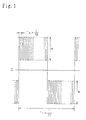
- FIG. 1 shows an example of waveform for making the discharge arc from a discharge lamp straight.
- This waveform provides the frequency component f2 of the acoustic resonant frequency for exciting a mode in which the discharge arc is made straight, which is determined by sound velocity of the discharge lamp in the discharge space medium and the length of the discharge space which intersects the discharge arc.
- This frequency component f2 can be obtained when re-ignited after extinction of the discharge lamp is taken sufficiently long.
- waveform As waveform, whose instantaneous value periodically fluctuates at the frequency component f2, there is used a waveform obtained by modulating the waveform of the frequency component f2 of the acoustic resonant frequency so that the polarity is changed at a modulation frequency f1 which is lower than the frequency component f2 of the acoustic resonant frequency.
- the depth of modulation (a value obtained by dividing ⁇ by the effective value ⁇ of the waveform (modulated signal waveform) of FIG. 1) is set to a predetermined value, it is possible to obtain a stable, straight discharge arc at the time of operation under the rated condition if extinction of the discharge lamp is sufficiently long.
- FIGS. 2(a) to 2(c) are views schematically showing a result obtained by observing a state of growth of a discharge arc when the discharge lamp is caused to re-ignite at the waveform shown in FIG. 1 before extinction thereof becomes sufficiently long.
- numeral 1 designates a pair of electrodes which are hermetically sealed within a glass envelope and are opposed to each other, and numeral 2 designates a discharge arc generated between the pair of electrodes 1.
- FIG. 2(a) is an example showing a state of dielectric breakdown when the discharge lamp starts discharging. Although the discharge occurs between electrodes 1, FIG.
- FIG. 2(a) shows an example in which the discharge has an S-shaped configuration, but other discharges are largely curved in the glass envelope direction, and there are few cases where discharge is performed over the shortest distance between the electrodes 1, i.e., straight. This is attributable to the un-uniform temperature distribution within the discharge space after putting out the light as described above.
- FIG. 2(b) shows a state of the discharge arc until operation under the rated condition is reached after the discharge had started, and the discharge arc grows maintaining the curved state of the discharge arc shown in FIG. 2(a).
- FIG. 2(c) shows a state of the discharge arc when operation under the rated condition is reached, and it can be seen that any stable, straight discharge arc cannot be obtained.
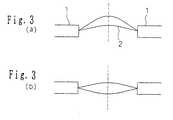
- FIG. 3(a) shows the shape of the discharge arc when the depth of modulation is made smaller by making ⁇ in FIG. 1 smaller from the state shown in FIG. 2(b) or FIG. 2(c).
- numeral 1 designates a pair of electrodes which are opposed to each other
- numeral 2 designates a discharge arc occurring between the pair of electrodes 1 as in the case of FIG. 2(a). If the depth of modulation is made smaller, the intensity of a compression wave emitted from the discharge arc becomes lower, and the level of acoustic resonance also becomes lower.
- the deformation of the discharge arc is mainly caused under the influence of buoyancy due to gravity-induced convection caused by temperature distribution (center of discharge arc: about 5,000 K to 7,000 K, near the glass envelope: about 1,000 K) within the discharge space during operation, and the discharge arc is slightly curved upwardly.
- the depth of modulation is preferably set to 0.3 or less in order to sufficiently reduce the influence of the acoustic resonance.
- FIG. 3(b) shows a shape of the discharge arc when the depth of modulation is at first made smaller and thereafter is made larger. A stable, straight discharge arc can be formed.
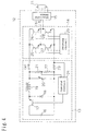
- FIG. 4 is a structural view showing the first embodiment, in which numeral 11 designates a discharge lamp in which mercury and metal halide have been hermetically sealed as filling material within a glass envelope for defining the discharge space.
- numeral 12 designates operating means for supplying the waveform of FIG. 1 to the discharge lamp 11 for operation.
- the operating means 12 comprises: in the case of re-ignition after sufficient extinction, a DC power source 13, which is a generation means for generating a waveform signal which has a waveform having a frequency component of an acoustic resonant frequency for exciting a mode, in which the discharge arc is made straight, whose center line is maintained at a constant level; an inverter circuit 14, which is a modulation means for modulating the waveform signal so that the polarity is alternately changed at a modulation frequency, which has the center line of the waveform signal lower than the acoustic resonant frequency; and starting means 15 for applying a high voltage enough to start discharging of the discharge lamp 11 thereto.
- the center line of the waveform which the DC power source 13 generates may not always be at a constant level.
- a step-down chopper circuit is constituted by: a DC power source 16; a transistor 17; a diode 18; a chopper coil 19; and a capacitor 20 capable of varying its electrostatic capacity, in such a manner that the lamp power is calculated by a control circuit 24 from a detection signal corresponding to lamp voltage detected by resistance 21 and 22, and a detection signal corresponding to lamp current detected by resistance 23, and further that the on-off ratio of the transistor 17 is made variable so that the lamp power becomes a rated value.
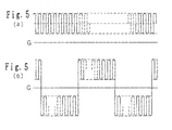
- the on-off frequency of the transistor 17 is set to an acoustic resonant frequency for exciting the mode in which the discharge arc is made straight, and a filter circuit consisting of the choke coil 19 and the capacitor 20 is caused to have the special property that the frequency component of the acoustic resonant frequency is not cut, the output current waveform of the DC power source 13 will become a waveform in which a predetermined DC bias is superposed on a center line whose instantaneous value periodically fluctuates at an acoustic resonant frequency for exciting the mode in which the discharge arc is made straight as shown in FIG. 5(a).
- An inverter circuit 14 is constituted by transistors 25, 26, 27 and 28, and a driving circuit 29 in such a manner that a period in which the transistors 25 and 28 are turned on and a period in which the transistors 26 and 27 are turned on are caused to alternately occur through an output signal from the driving circuit 29, whereby the output waveform from the DC power source 13 is converted into such waveform as shown in FIG. 5(b) whose polarity is alternately changed at a modulation frequency, which is lower than the acoustic resonant frequency to supply it to the discharge lamp 11.
- the discharge lamp 11 which has started discharging at high voltage of starting means 15 lights at the waveform shown in FIG. 5(b).
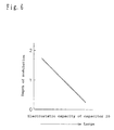
- FIG. 6 shows relationship between the electrostatic capacity of the capacitor 20 and the depth of modulation, and the depth of modulation becomes smaller as the electrostatic capacity of the capacitor 20 is increased, while the depth of modulation becomes larger as the electrostatic capacity is decreased.
- FIGs. 7(a) and 7(b) show an example of change characteristic of the electrostatic capacity of the capacitor 20 with respect to elapsed time after operating. If a predetermined electrostatic capacity of a feedback capacitor 20 after operating is made large, and is stepwise made smaller as shown in FIG. 7(a), it is possible to stepwise increase the depth of modulation of the discharge lamp 11 at the beginning of operation. At this time, the discharge arc slightly curves upwardly while the depth of modulation is small, and thereafter, it is switched to a straight discharge arc. Therefore, visual flicker due to a change in the shape of the discharge arc is predicted, but it is possible to prevent the flickering by setting a period in which the electrostatic capacity of the capacitor 20 is large to 10 ms or less.
- FIG. 7(b) shows that the electrostatic capacity of the capacitor 20 is made large during a predetermined period after operation, and is gradually made smaller, and the depth of modulation of the discharge lamp 11 at the beginning of operation can be gradually increased.
- the shape of the discharge arc gradually changes from a curved discharge arc to a straight discharge arc, and does not change instantaneously. Therefore, there is provided a remarkable effect that it is possible to prevent the visual flicker, and also to prevent an unstable operation of the discharge arc which is likely to occur at transient time of switching from the curved discharge arc to the straight discharge arc.
- FIG. 8 shows a relationship between the on-off frequency of the transistor 17 when the electrostatic capacity of the capacitor 20 in the first embodiment is made constant, and the depth of modulation.
- the on-off frequency of the transistor 17 is made higher, the depth of modulation becomes smaller, while when the on-off frequency is made lower, the depth of modulation becomes larger. This is attributable to the special property that higher frequency components are cut from the frequency characteristic determined by the inductance of the choke coil 19 and the electrostatic capacity of the capacitor 20 in the filter circuit.
- an acoustic resonant frequency for exciting the mode in which the discharge arc is made straight is a function of gas temperature within the discharge space, and has the special property that it decreases until this gas temperature reaches operation under the rated condition. Therefore, the acoustic resonant frequency which makes the discharge arc straight has the special property that it decreases until operation under the rated condition is reached.
- the structure is arranged such that there is provided frequency varying means which changes the on-off frequency of the transistor 17 so as to synchronize with the change in the acoustic resonant frequency, the stability of the discharge arc at the beginning of operation is improved, and it is possible to obtain a stable, straight discharge arc from the beginning of operation to operation under the rated condition irrespective of extinction of the discharge lamp.
- both a HID lamp such as a high-pressure mercury lamp, a metal halide lamp and a high-pressure sodium lamp may be used.
- the structure has been arranged such that the electrostatic capacity of the capacitor 20 is caused to change with the lapse of time after operation of the discharge lamp 11 to make the depth of modulation variable, but it may be possible to construct such that detection means for detecting the lamp characteristic is provided to detect whether or not it is at the beginning of operation, and that the electrostatic capacity of the capacitor 20 is made variable in response to output from the detection means.
- detection means for detecting the lamp characteristic is provided to detect whether or not it is at the beginning of operation, and that the electrostatic capacity of the capacitor 20 is made variable in response to output from the detection means.
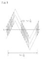
- the inverter circuit 14 has been modulated like a rectangular wave, it may be possible to construct such that it is modulated into a nearly trapezoidal wave shape having tilted leading and falling edges of the waveform. Also, it may be possible to use any structure capable of generating a modulation signal as the polarity is changed at a lower modulation frequency, such as a sinusoidal wave, a triangular wave, a stepped wave and a saw tooth wave (See FIG. 9) except a nearly rectangular wave, than an acoustic resonant frequency for exciting the mode in which the discharge arc is made straight. Furthermore, the polarity need only be changed even if the modulation signal contains more or less DC components, and any positive-negative asymmetrical waveform may be used.
- the DC power source 13 has been constituted by a step-down chopper circuit
- other circuit systems such as a step-up chopper circuit and an inversion chopper circuit may be used, and other structures may be used so long as there can be outputted a waveform in which a predetermined DC bias has been superimposed on a center line whose instantaneous value periodically fluctuates at an acoustic resonant frequency for exciting the mode in which the discharge arc is made straight.
- control circuit 24 has been constructed to control the on-off ratio of the transistor 17 so that the lamp power becomes a rated value
- the structure may be arranged such that there is provided an effective value varying means for varying the effective value of a modulation signal to vary the lamp power.
- it is effective for supplying power exceeding the rated value at the beginning of operation in order to supplement the optical output at the beginning of operation, and controlling modulated light among others.
- the present invention is capable of realizing an excellent discharge lamp operating apparatus capable of preventing unstable phenomena such as deformation of a discharge arc, and forming a stable, straight discharge arc irrespective of extinction of the discharge lamp.
Landscapes
- Circuit Arrangements For Discharge Lamps (AREA)
Claims (12)
- Appareil (12) de mise en oeuvre de lampe à décharge destiné à mettre en oeuvre une lampe à décharge (11) comportant une enveloppe de verre destinée à définir un espace de décharge et une paire d'électrodes (1) qui sont hermétiquement scellées au sein de l'enveloppe de verre et sont opposées l'une à l'autre, comprenant :caractérisé en ce que,un moyen de génération (13) pour générer un signal de forme d'onde ayant une composante de fréquence d'une fréquence de résonance acoustique (f2) afin d'exciter un mode dans lequel un arc de décharge (2) se produisant entre ladite paire d'électrodes (1) est rendu droit ; etun moyen de modulation 14 pour moduler ledit signal de forme d'onde de sorte que la polarité de l'axe dudit signal de forme d'onde est alternativement changée à une fréquence de modulation (f1) possédant une fréquence inférieure à la composante de fréquence de ladite fréquence de résonance acoustique,
en supposant qu'une valeur dudit signal de forme d'onde de pic à pic soit α, et qu'une valeur efficace dudit signal modulé soit β, la profondeur de modulation α/β au niveau de la sortie dudit moyen de modulation (14) à un commencement de mise en oeuvre de ladite lampe à décharge, lorsqu'elle est activée de nouveau après avoir été désactivée pendant un temps insuffisamment long, et rendue plus petite que la profondeur de modulation α/β lors d'une mise en oeuvre sous la condition nominale. - Appareil de mise en oeuvre de lampe à décharge selon la revendication 1, dans lequel
l'axe de α (valeur moyenne d'α) est maintenu à un niveau constant. - Appareil de mise en oeuvre de lampe à décharge selon la revendication 1 ou 2, dans lequel
ladite fréquence de résonance acoustique est déterminée par une vitesse du son dans un milieu d'espace de décharge de la lampe à décharge, et une longueur de l'espace de décharge, la longueur coupant ledit arc de décharge. - Appareil de mise en oeuvre de lampe à décharge selon la revendication 1 ou 2, dans lequel,
une période dans laquelle ladite profondeur de modulation α/β de ladite lampe à décharge au commencement de la mise en oeuvre est rendue plus petite qu'une profondeur de modulation α/β à la mise en oeuvre sous la condition nominale est effectivement une période entière jusqu'à ce que la mise en oeuvre sous la condition nominale soit atteinte. - Appareil de mise en oeuvre de lampe à décharge selon la revendication 1 ou 2,
dans lequel une période dans laquelle ladite profondeur de modulation α/β de ladite lampe à décharge au commencement de la mise en oeuvre est rendue plus petite qu'une profondeur de modulation α/β à la mise en oeuvre sous la condition nominale est de 10 ms ou moins. - Appareil de mise en oeuvre de lampe à décharge selon la revendication 1 ou 2, dans lequel
au commencement de la mise en oeuvre, il existe une période telle que ladite profondeur de modulation α/β a une valeur de 0,3 ou moins. - Appareil de mise en oeuvre de lampe à décharge selon la revendication 1 ou 2, dans lequel
ledit appareil de mise en oeuvre de lampe à décharge comporte un moyen de détection 24 destiné à détecter une caractéristique de lampe de ladite lampe à décharge et change ladite profondeur de modulation α/β en réponse à un changement de ladite caractéristique de lampe. - Appareil de mise en oeuvre de lampe à décharge selon la revendication 7, dans lequel
ledit moyen de détection (21, 22, 24) détecte la température de l'ampoule, la tension de lampe, l'impédance de lampe ou la sortie optique comme caractéristique de lampe. - Appareil de mise en oeuvre de lampe à décharge selon la revendication 1 ou 2, dans lequel
ladite profondeur de modulation α/β de ladite lampe à décharge au début de fonctionnement possède une période durant laquelle la profondeur de modulation α/β augmente graduellement. - Appareil de mise en oeuvre de lampe à décharge selon la revendication 1 ou 2, dans lequel
ladite profondeur de modulation α/β de ladite lampe à décharge, au niveau du commencement de la mise en oeuvre, possède une période dans laquelle la profondeur de modulation α/β augmente pas à pas. - Appareil de mise oeuvre de lampe à décharge selon la revendication 1 ou 2, dans lequel
ledit moyen de génération comporte un moyen de variation de fréquence afin de générer une forme d'onde ayant une composante de fréquence en réponse à un changement de la composante de fréquence de la fréquence de résonance acoustique pour exciter le mode dans lequel un arc de décharge est rendu droit. - Appareil de mise en oeuvre de lampe à décharge selon la revendication 1, 2 ou 10, dans lequel
ledit moyen de modulation comporte un moyen de variation de valeur efficace pour modifier la valeur efficace dudit signal modulé.
Applications Claiming Priority (3)
| Application Number | Priority Date | Filing Date | Title |
|---|---|---|---|
| JP26166897A JP3246407B2 (ja) | 1997-09-26 | 1997-09-26 | 放電ランプ点灯装置 |
| JP26166897 | 1997-09-26 | ||
| JP261668/97 | 1997-09-26 |
Publications (3)
| Publication Number | Publication Date |
|---|---|
| EP0906003A2 EP0906003A2 (fr) | 1999-03-31 |
| EP0906003A3 EP0906003A3 (fr) | 1999-06-02 |
| EP0906003B1 true EP0906003B1 (fr) | 2002-12-11 |
Family
ID=17365097
Family Applications (1)
| Application Number | Title | Priority Date | Filing Date |
|---|---|---|---|
| EP98118095A Expired - Lifetime EP0906003B1 (fr) | 1997-09-26 | 1998-09-24 | Appareil pour alimenter une lampe à décharge |
Country Status (6)
| Country | Link |
|---|---|
| US (1) | US6130508A (fr) |
| EP (1) | EP0906003B1 (fr) |
| JP (1) | JP3246407B2 (fr) |
| KR (1) | KR19990030118A (fr) |
| CN (1) | CN1213264A (fr) |
| DE (1) | DE69810053T2 (fr) |
Families Citing this family (9)
| Publication number | Priority date | Publication date | Assignee | Title |
|---|---|---|---|---|
| US6124683A (en) * | 1999-04-14 | 2000-09-26 | Osram Sylvania Inc. | System for and method of operating a mercury free discharge lamp |
| TW530521B (en) * | 2000-08-28 | 2003-05-01 | Koninkl Philips Electronics Nv | Circuit device for operating a high-pressure discharge lamp with successive current phases |
| US6476566B2 (en) | 2000-12-27 | 2002-11-05 | Infocus Systems, Inc. | Method and apparatus for canceling ripple current in a lamp |
| JP4190734B2 (ja) * | 2001-01-15 | 2008-12-03 | ウシオ電機株式会社 | 誘電体バリア放電ランプ光源装置 |
| JP2007115660A (ja) * | 2005-09-22 | 2007-05-10 | Toshiba Lighting & Technology Corp | 高圧放電ランプ点灯装置及び照明装置 |
| KR20090113329A (ko) * | 2007-02-13 | 2009-10-29 | 코닌클리즈케 필립스 일렉트로닉스 엔.브이. | 가스 방전 램프를 구동하기 위한 장치 |
| JP2009026548A (ja) * | 2007-07-18 | 2009-02-05 | Stanley Electric Co Ltd | 放電灯点灯装置 |
| DE102010028921A1 (de) * | 2010-05-12 | 2011-11-17 | Osram Gesellschaft mit beschränkter Haftung | Verfahren zum Betrieb einer Hochdruckentladungslampe auf der Basis eines niederfrequenten Rechteckbetriebs und einem teilweisen Hochfrequenten Betrieb zur Bogenstabilisierung und zur Farbdurchmischung |
| DE102014013353A1 (de) * | 2014-09-05 | 2016-03-10 | B & S Elektronische Geräte GmbH | Vorschaltgerät und Verfahren zur Steuerung eines Vorschaltgeräts |
Family Cites Families (9)
| Publication number | Priority date | Publication date | Assignee | Title |
|---|---|---|---|---|
| US5121034A (en) * | 1989-03-08 | 1992-06-09 | General Electric Company | Acoustic resonance operation of xenon-metal halide lamps |
| US4983889A (en) * | 1989-05-15 | 1991-01-08 | General Electric Company | Discharge lamp using acoustic resonant oscillations to ensure high efficiency |
| US5198727A (en) * | 1990-02-20 | 1993-03-30 | General Electric Company | Acoustic resonance operation of xenon-metal halide lamps on unidirectional current |
| US5047695A (en) * | 1990-02-20 | 1991-09-10 | General Electric Company | Direct current (DC) acoustic operation of xenon-metal halide lamps using high-frequency ripple |
| JPH0479835A (ja) * | 1990-07-24 | 1992-03-13 | Mimii:Kk | パン及びその製造方法 |
| US5270620A (en) * | 1990-09-04 | 1993-12-14 | General Electric Company | High frequency resonant converter for operating metal halide lamps |
| DE4317368A1 (de) * | 1993-05-25 | 1994-12-01 | Patent Treuhand Ges Fuer Elektrische Gluehlampen Mbh | Verfahren zum Betrieb einer Hochdruckentladungslampe |
| EP0713352B1 (fr) * | 1994-11-18 | 2001-10-17 | Matsushita Electric Industrial Co., Ltd. | Appareil d'éclairage à lampe à décharge |
| US5684367A (en) * | 1996-01-16 | 1997-11-04 | Osram Sylvania Inc. | Color control and arc stabilization for high-intensity, discharge lamps |
-
1997
- 1997-09-26 JP JP26166897A patent/JP3246407B2/ja not_active Expired - Fee Related
-
1998
- 1998-09-24 US US09/160,274 patent/US6130508A/en not_active Expired - Fee Related
- 1998-09-24 EP EP98118095A patent/EP0906003B1/fr not_active Expired - Lifetime
- 1998-09-24 DE DE69810053T patent/DE69810053T2/de not_active Expired - Fee Related
- 1998-09-25 KR KR1019980039832A patent/KR19990030118A/ko not_active Withdrawn
- 1998-09-28 CN CN98119447A patent/CN1213264A/zh active Pending
Also Published As
| Publication number | Publication date |
|---|---|
| JP3246407B2 (ja) | 2002-01-15 |
| KR19990030118A (ko) | 1999-04-26 |
| JPH11102790A (ja) | 1999-04-13 |
| CN1213264A (zh) | 1999-04-07 |
| DE69810053D1 (de) | 2003-01-23 |
| US6130508A (en) | 2000-10-10 |
| DE69810053T2 (de) | 2003-07-17 |
| EP0906003A2 (fr) | 1999-03-31 |
| EP0906003A3 (fr) | 1999-06-02 |
Similar Documents
| Publication | Publication Date | Title |
|---|---|---|
| US7122960B2 (en) | Emission device for an ultra-high pressure mercury lamp | |
| JP4990490B2 (ja) | 高圧放電ランプ点灯装置、高圧放電ランプ装置、投射型画像表示装置及び高圧放電ランプ点灯方法 | |
| CN100452939C (zh) | 高压放电灯点灯装置 | |
| US6005356A (en) | Operating method and operating apparatus for a high pressure discharge lamp | |
| JP5193445B2 (ja) | 高圧放電灯点灯装置及び照明器具 | |
| EP0825808B1 (fr) | Appareil et procédé pour alimenter une lampe à décharge | |
| JP4171285B2 (ja) | 高圧放電灯の点灯方法および点灯装置 | |
| US6225754B1 (en) | Operating method and operating apparatus for a high pressure discharge lamp | |
| EP0906003B1 (fr) | Appareil pour alimenter une lampe à décharge | |
| JP3851343B2 (ja) | 高圧放電ランプ点灯装置 | |
| CN1216211A (zh) | 电路装置 | |
| GB2375444A (en) | Improved lamp colour control for dimmed high intensity discharge lamps | |
| JP4135398B2 (ja) | 高圧放電灯点灯装置 | |
| CN1206884C (zh) | 直流金属卤化物弧光灯的工作方法及其电路装置 | |
| JP3201981B2 (ja) | 放電ランプ点灯装置及び方法 | |
| HK1017803A (en) | Discharge lamp operating apparatus | |
| US7045972B2 (en) | Lighting method of ultra-high pressure mercury lamp | |
| JP2006185663A (ja) | 点灯装置 | |
| US7154231B2 (en) | Gas discharge lamp dimming control method | |
| JP4572643B2 (ja) | セラミックメタルハライドランプの点灯装置及び照明装置 | |
| JP2002352990A (ja) | 放電灯点灯装置 | |
| JP2000113996A (ja) | 放電ランプ点灯装置 | |
| JP2003133096A (ja) | 放電灯点灯装置 | |
| KR100453712B1 (ko) | 메탈 할라이드 램프용 고주파 전자식 안정기의 다중 변조구동 방법 및 장치 | |
| JPH0963783A (ja) | 放電ランプ点灯装置 |
Legal Events
| Date | Code | Title | Description |
|---|---|---|---|
| PUAI | Public reference made under article 153(3) epc to a published international application that has entered the european phase |
Free format text: ORIGINAL CODE: 0009012 |
|
| AK | Designated contracting states |
Kind code of ref document: A2 Designated state(s): DE FR GB |
|
| AX | Request for extension of the european patent |
Free format text: AL;LT;LV;MK;RO;SI |
|
| PUAL | Search report despatched |
Free format text: ORIGINAL CODE: 0009013 |
|
| AK | Designated contracting states |
Kind code of ref document: A3 Designated state(s): AT BE CH CY DE DK ES FI FR GB GR IE IT LI LU MC NL PT SE |
|
| AX | Request for extension of the european patent |
Free format text: AL;LT;LV;MK;RO;SI |
|
| 17P | Request for examination filed |
Effective date: 19990928 |
|
| AKX | Designation fees paid |
Free format text: DE FR GB |
|
| 17Q | First examination report despatched |
Effective date: 20000225 |
|
| RIC1 | Information provided on ipc code assigned before grant |
Free format text: 7H 05B 41/292 A |
|
| GRAG | Despatch of communication of intention to grant |
Free format text: ORIGINAL CODE: EPIDOS AGRA |
|
| GRAG | Despatch of communication of intention to grant |
Free format text: ORIGINAL CODE: EPIDOS AGRA |
|
| GRAH | Despatch of communication of intention to grant a patent |
Free format text: ORIGINAL CODE: EPIDOS IGRA |
|
| GRAH | Despatch of communication of intention to grant a patent |
Free format text: ORIGINAL CODE: EPIDOS IGRA |
|
| GRAA | (expected) grant |
Free format text: ORIGINAL CODE: 0009210 |
|
| AK | Designated contracting states |
Kind code of ref document: B1 Designated state(s): DE FR GB |
|
| REG | Reference to a national code |
Ref country code: GB Ref legal event code: FG4D |
|
| REF | Corresponds to: |
Ref document number: 69810053 Country of ref document: DE Date of ref document: 20030123 |
|
| ET | Fr: translation filed | ||
| PLBE | No opposition filed within time limit |
Free format text: ORIGINAL CODE: 0009261 |
|
| STAA | Information on the status of an ep patent application or granted ep patent |
Free format text: STATUS: NO OPPOSITION FILED WITHIN TIME LIMIT |
|
| 26N | No opposition filed |
Effective date: 20030912 |
|
| REG | Reference to a national code |
Ref country code: HK Ref legal event code: WD Ref document number: 1017803 Country of ref document: HK |
|
| PGFP | Annual fee paid to national office [announced via postgrant information from national office to epo] |
Ref country code: FR Payment date: 20060908 Year of fee payment: 9 |
|
| PGFP | Annual fee paid to national office [announced via postgrant information from national office to epo] |
Ref country code: GB Payment date: 20060920 Year of fee payment: 9 |
|
| PGFP | Annual fee paid to national office [announced via postgrant information from national office to epo] |
Ref country code: DE Payment date: 20060922 Year of fee payment: 9 |
|
| GBPC | Gb: european patent ceased through non-payment of renewal fee |
Effective date: 20070924 |
|
| PG25 | Lapsed in a contracting state [announced via postgrant information from national office to epo] |
Ref country code: DE Free format text: LAPSE BECAUSE OF NON-PAYMENT OF DUE FEES Effective date: 20080401 |
|
| REG | Reference to a national code |
Ref country code: FR Ref legal event code: ST Effective date: 20080531 |
|
| PG25 | Lapsed in a contracting state [announced via postgrant information from national office to epo] |
Ref country code: FR Free format text: LAPSE BECAUSE OF NON-PAYMENT OF DUE FEES Effective date: 20071001 |
|
| PG25 | Lapsed in a contracting state [announced via postgrant information from national office to epo] |
Ref country code: GB Free format text: LAPSE BECAUSE OF NON-PAYMENT OF DUE FEES Effective date: 20070924 |