EP0906185B1 - Procede servant a fabriquer un recipient de pression et recipient de pression, particulierement pour un dispositif de rechauffement d'eau, fabrique au moyen de ce procede - Google Patents
Procede servant a fabriquer un recipient de pression et recipient de pression, particulierement pour un dispositif de rechauffement d'eau, fabrique au moyen de ce procede Download PDFInfo
- Publication number
- EP0906185B1 EP0906185B1 EP97926313A EP97926313A EP0906185B1 EP 0906185 B1 EP0906185 B1 EP 0906185B1 EP 97926313 A EP97926313 A EP 97926313A EP 97926313 A EP97926313 A EP 97926313A EP 0906185 B1 EP0906185 B1 EP 0906185B1
- Authority
- EP
- European Patent Office
- Prior art keywords
- pressure vessel
- plastic material
- walls
- pressure
- vessel
- Prior art date
- Legal status (The legal status is an assumption and is not a legal conclusion. Google has not performed a legal analysis and makes no representation as to the accuracy of the status listed.)
- Expired - Lifetime
Links
Images




Classifications
-
- B—PERFORMING OPERATIONS; TRANSPORTING
- B29—WORKING OF PLASTICS; WORKING OF SUBSTANCES IN A PLASTIC STATE IN GENERAL
- B29C—SHAPING OR JOINING OF PLASTICS; SHAPING OF MATERIAL IN A PLASTIC STATE, NOT OTHERWISE PROVIDED FOR; AFTER-TREATMENT OF THE SHAPED PRODUCTS, e.g. REPAIRING
- B29C45/00—Injection moulding, i.e. forcing the required volume of moulding material through a nozzle into a closed mould; Apparatus therefor
- B29C45/14—Injection moulding, i.e. forcing the required volume of moulding material through a nozzle into a closed mould; Apparatus therefor incorporating preformed parts or layers, e.g. injection moulding around inserts or for coating articles
- B29C45/14598—Coating tubular articles
-
- B—PERFORMING OPERATIONS; TRANSPORTING
- B29—WORKING OF PLASTICS; WORKING OF SUBSTANCES IN A PLASTIC STATE IN GENERAL
- B29C—SHAPING OR JOINING OF PLASTICS; SHAPING OF MATERIAL IN A PLASTIC STATE, NOT OTHERWISE PROVIDED FOR; AFTER-TREATMENT OF THE SHAPED PRODUCTS, e.g. REPAIRING
- B29C45/00—Injection moulding, i.e. forcing the required volume of moulding material through a nozzle into a closed mould; Apparatus therefor
- B29C45/14—Injection moulding, i.e. forcing the required volume of moulding material through a nozzle into a closed mould; Apparatus therefor incorporating preformed parts or layers, e.g. injection moulding around inserts or for coating articles
- B29C45/14836—Preventing damage of inserts during injection, e.g. collapse of hollow inserts, breakage
-
- B—PERFORMING OPERATIONS; TRANSPORTING
- B29—WORKING OF PLASTICS; WORKING OF SUBSTANCES IN A PLASTIC STATE IN GENERAL
- B29C—SHAPING OR JOINING OF PLASTICS; SHAPING OF MATERIAL IN A PLASTIC STATE, NOT OTHERWISE PROVIDED FOR; AFTER-TREATMENT OF THE SHAPED PRODUCTS, e.g. REPAIRING
- B29C45/00—Injection moulding, i.e. forcing the required volume of moulding material through a nozzle into a closed mould; Apparatus therefor
- B29C45/16—Making multilayered or multicoloured articles
- B29C45/1642—Making multilayered or multicoloured articles having a "sandwich" structure
-
- B—PERFORMING OPERATIONS; TRANSPORTING
- B29—WORKING OF PLASTICS; WORKING OF SUBSTANCES IN A PLASTIC STATE IN GENERAL
- B29C—SHAPING OR JOINING OF PLASTICS; SHAPING OF MATERIAL IN A PLASTIC STATE, NOT OTHERWISE PROVIDED FOR; AFTER-TREATMENT OF THE SHAPED PRODUCTS, e.g. REPAIRING
- B29C45/00—Injection moulding, i.e. forcing the required volume of moulding material through a nozzle into a closed mould; Apparatus therefor
- B29C45/17—Component parts, details or accessories; Auxiliary operations
- B29C45/26—Moulds
- B29C45/261—Moulds having tubular mould cavities
-
- F—MECHANICAL ENGINEERING; LIGHTING; HEATING; WEAPONS; BLASTING
- F24—HEATING; RANGES; VENTILATING
- F24H—FLUID HEATERS, e.g. WATER OR AIR HEATERS, HAVING HEAT-GENERATING MEANS, e.g. HEAT PUMPS, IN GENERAL
- F24H1/00—Water heaters, e.g. boilers, continuous-flow heaters or water-storage heaters
- F24H1/18—Water-storage heaters
- F24H1/181—Construction of the tank
-
- F—MECHANICAL ENGINEERING; LIGHTING; HEATING; WEAPONS; BLASTING
- F24—HEATING; RANGES; VENTILATING
- F24H—FLUID HEATERS, e.g. WATER OR AIR HEATERS, HAVING HEAT-GENERATING MEANS, e.g. HEAT PUMPS, IN GENERAL
- F24H1/00—Water heaters, e.g. boilers, continuous-flow heaters or water-storage heaters
- F24H1/18—Water-storage heaters
- F24H1/20—Water-storage heaters with immersed heating elements, e.g. electric elements or furnace tubes
- F24H1/201—Water-storage heaters with immersed heating elements, e.g. electric elements or furnace tubes using electric energy supply
-
- B—PERFORMING OPERATIONS; TRANSPORTING
- B29—WORKING OF PLASTICS; WORKING OF SUBSTANCES IN A PLASTIC STATE IN GENERAL
- B29K—INDEXING SCHEME ASSOCIATED WITH SUBCLASSES B29B, B29C OR B29D, RELATING TO MOULDING MATERIALS OR TO MATERIALS FOR MOULDS, REINFORCEMENTS, FILLERS OR PREFORMED PARTS, e.g. INSERTS
- B29K2101/00—Use of unspecified macromolecular compounds as moulding material
- B29K2101/10—Thermosetting resins
-
- B—PERFORMING OPERATIONS; TRANSPORTING
- B29—WORKING OF PLASTICS; WORKING OF SUBSTANCES IN A PLASTIC STATE IN GENERAL
- B29K—INDEXING SCHEME ASSOCIATED WITH SUBCLASSES B29B, B29C OR B29D, RELATING TO MOULDING MATERIALS OR TO MATERIALS FOR MOULDS, REINFORCEMENTS, FILLERS OR PREFORMED PARTS, e.g. INSERTS
- B29K2105/00—Condition, form or state of moulded material or of the material to be shaped
- B29K2105/06—Condition, form or state of moulded material or of the material to be shaped containing reinforcements, fillers or inserts
- B29K2105/16—Fillers
-
- B—PERFORMING OPERATIONS; TRANSPORTING
- B29—WORKING OF PLASTICS; WORKING OF SUBSTANCES IN A PLASTIC STATE IN GENERAL
- B29L—INDEXING SCHEME ASSOCIATED WITH SUBCLASS B29C, RELATING TO PARTICULAR ARTICLES
- B29L2022/00—Hollow articles
-
- B—PERFORMING OPERATIONS; TRANSPORTING
- B29—WORKING OF PLASTICS; WORKING OF SUBSTANCES IN A PLASTIC STATE IN GENERAL
- B29L—INDEXING SCHEME ASSOCIATED WITH SUBCLASS B29C, RELATING TO PARTICULAR ARTICLES
- B29L2031/00—Other particular articles
- B29L2031/712—Containers; Packaging elements or accessories, Packages
-
- F—MECHANICAL ENGINEERING; LIGHTING; HEATING; WEAPONS; BLASTING
- F24—HEATING; RANGES; VENTILATING
- F24H—FLUID HEATERS, e.g. WATER OR AIR HEATERS, HAVING HEAT-GENERATING MEANS, e.g. HEAT PUMPS, IN GENERAL
- F24H1/00—Water heaters, e.g. boilers, continuous-flow heaters or water-storage heaters
-
- F—MECHANICAL ENGINEERING; LIGHTING; HEATING; WEAPONS; BLASTING
- F24—HEATING; RANGES; VENTILATING
- F24H—FLUID HEATERS, e.g. WATER OR AIR HEATERS, HAVING HEAT-GENERATING MEANS, e.g. HEAT PUMPS, IN GENERAL
- F24H1/00—Water heaters, e.g. boilers, continuous-flow heaters or water-storage heaters
- F24H1/18—Water-storage heaters
- F24H1/188—Water-storage heaters with means for compensating water expansion
Definitions
- the present invention relates to process for the manufacturing of a pressure vessel and a pressure vessel, especially for a water heater, received through the process.
- Water heaters in different sizes for both household and industrial purposes normally includes a pressure vessel which without exceptions are made from metal.
- the heating of the water is achieved by using an electrical heater which normally is constituted by a metal tube containing a heating filament embedded in a mineral or a ceramic material.
- the heater is guided by a sensor which detects the temperature of the water.
- the existing pressure of the water supply system is normally used when feeding hot water from the water heater wherein the heater can be placed independently. This is achieved by means of a clack valve which is placed on the cold water inlet of the water heater. This valve will open and replace hot water with cold water as soon as the pressure in the water heater becomes lower as the hot water are drawn from the water heater.
- the pressure vessel is normally insulated to minimise the energy losses.
- the temperature range is normally 50 - 90°C.
- One disadvantage with the water heaters of today is that they are manufactured from a metal. It often becomes necessary to provide the pressure vessel with a sacrificial anode to avoid galvanic corrosion since metal is a good conductor. It is possible to use a more noble metal for the pressure vessel to avoid this type of corrosion but that would only move the problem with corrosion to the parts of the water supply system that are made of less noble metals. Metals are also good heat conductors which increases energy losses. Another disadvantage is caused by the thermal expansion of the water. Most materials expands when the temperature increases, so do most metals, however not enough to compensate for the expansion of the water. This means that the pressure in a water heater completely filled with cold water will increase as the temperature of the water increases.
- the temperature of the water in the vessel will be mainly homogenous.
- the water temperature in the vessel will thereby also decrease mainly homogeneously as cold water are supplied in connection with the use of hot water from the water heater.
- WO 93/13341 discloses a pressure vessel including a dome-section forming the upper end of the pressure vessel or, alternatively, two dome-sections forming the upper end and the lower end of the pressure vessel. Further, a circumfering cell connects the dome-shaped sections or the dome-shaped upper section and a flat bottom section. A number of parting and load distributing walls are provided such that cells are formed inside the pressure vessel.
- the pressure vessel comprises openings which extend through the compartment walls and/or an outer wall or a flat bottom wall of the pressure vessel.
- the invention relates to a process for the manufacturing of a pressure vessel made from thermoplastic material or thermosetting resin.
- the pressure vessel comprises a first and a second vessel end part manufactured through injection moulding or press moulding and possibly an intermediate tube part which preferably is manufactured through extrusion.
- the vessel end parts include a circumfering cell which form the sides of the pressure vessel and each one dome which form the upper and the lower ends respectively of the pressure vessel when joined. A number of interconnecting and thereby load distributing walls stretch from the domes along the circumfering cell towards the open part of each vessel end part.
- a corresponding number of matching walls stretch from one open end of the possible interimediate tube part along the circumfering cell of the tube part to the other end of the same so that when two vessel end parts are joined, possibly with an intermediate tube part placed in between, the edges of each of the walls in the different parts meet.
- a number of cells are hereby formed between the walls.
- the walls are placed so that a number of crossing areas are formed between intersecting or connecting walls.
- the invention is characterised in that at least one, preferably all crossing areas are provided with a termination by achieving a hole from the outside of the dome.
- the hole area is larger than the crossing area and the depth of the hole greater than the goods thickness of the dome part.
- Communicating openings between the cells in the pressure vessel are hereby prepared.
- the possibly intermediate tube parts are preferably manufactured by extrusion. They can however also be manufactured by means of injection moulding possibly assisted b y melt core technologies or the like.
- the vessel end parts and the possible intermediate tube part are suitably joined by mirror welding, friction welding, pressing or gluing.
- the holes are preferably achieved in connection with the manufacturing of the vessel end parts and then by means of peg-like parts placed in one of the halves of a mould.
- the holes can also be achieved through after-treatment by drilling, milling or the like.
- One or more of peg-like parts which is/are placed in one of the mould halves and/or opposite points at the other half of the mould is/are suitably provided with an axially placed long core or cores whose cross-section area are smaller than the cross-section area of the crossing area.
- At least one channel which is parallel to, and having the full length of the walls are hereby formed in the cross-section of the crossing area.
- the two halves of the mould are provided with receiving means, placed axially with the peg-like parts.
- the receiving means are intended to receive a preferably extruded tube.
- the tube is manufactured of a thermosetting resin or a thermoplastic material. In cases where the tube is manufactured from a thermoplastic material, the melting temperature of the material in the tube should be at least as high as the melting temperature of the material used for the manufacturing of the vessel.
- the tube is placed in the mould cavity of the mould, after which a fluent plastic material is injected into the mould cavity while the receiving means prevents intrusion of plastic material into the tube through a tight fit between the receiving means and the edges of the tube.
- a gas is suitably injected into the tube simultaneously with the injection of the plastic material.
- a pressure mainly corresponding to the pressure of the injected fluent plastic material hereby forms within the tube.
- the tube is hereby also prevented from collapsing under influence of the injection pressure of the plastic material. This will further make use of tubes with very thin walls possible.
- the tube can be replaced by a so called melt core profile.
- the two halves of the mould are here provided with receiving means, placed axially with the peg-like parts.
- the receiving means are intended to receive the melt core profile which is placed into the mould whereupon the fluent plastic material is injected into the mould cavity.
- the melt core profile is then removed by melting after allowing the plastic material to solidify and removal of the part from the mould.
- At least one through-hole channel which is parallel to the walls is hereby formed in the cross-section of the crossing area.
- the mould can as an alternative be provided with means for melting of the melt core profile whereby the profile can be removed while the part is still located in the mould.
- a predetermined amount of fluent plastic material is injected into the mould cavity.
- the fluent plastic material is allowed to solidify somewhat, after which a gas is injected into the plastic material through the peg-like parts or the opposite points in the other half of the mould.
- At least one channel which is parallel to the walls is hereby formed in the cross-section of the crossing area.
- the holes are preferably provided with a plug selected from the group consisting of a blind plug, a channel connection plug connected to the channels, a main connection plug connected directly to the pressure vessel or a closing plug adapted to restriction or shut down of the flow through the communicating openings.
- the plugs are glued, screwed, friction welded, mirror welded or pressed into the holes in the domes.
- the plugs can be manufactured from metal or plastic material, however the latter is preferred.
- the two vessel end parts and the possible intermediate tube part are manufactured through injection moulding from two, preferably thermoplastic, compositions.
- a first predetermined amount of a fluent plastic material A is injected into the mould cavity after which a second remaining amount of a fluent plastic material B is injected so that the plastic material A in the main will enclose the plastic material B.
- the plastic material A is suitably a pure, non-filled thermoplastic material selected from polyethylene, polypropylene, polybutene, polyamide, polycarbonate, polyalkyleneterephthalate, polyvinylchloride, polystyrene, cross-linked polyethylene or the like.
- the plastic material B is one of the above materials, preferably the same as the material A, mixed with 1 - 35 % of a material selected from glass fibre, carbon fibre, steel fibre, mica, lime or the like.
- the plastic material A is a pure, non-filled thermoplastic material selected from polyethylene, polypropylene, polybutene, polyamide, polycarbonate, polyalkyleneterephthalate, polyvinylchloride, polystyrene, cross-linked polyethylene or the like.
- the plastic material B is one of the above materials, preferably the same as the material A, mixed with 20 - 70 % of an electrically conductive material selected from graphite nodules, carbon fibre, steel fibre or the like.
- the stratum formed by the plastic material B is connected to an electrical conductor so that a current flows through the stratum, whereby the stratum will work as a heating element.
- a pressure vessel provided with a heater can be achieved with a minimum of added parts.
- the invention also relates to a pressure vessel for an improved water heater achieved through the process, wherein the pressure vessel includes two domes which forms the upper and the lower end of the pressure vessel and a circumfering shell which forms the sides of the vessel.
- the pressure vessel also contains a number of parting and load distributing walls, stretching from one dome to the other dome along the circumfering shell, wherein a number of cells are formed in the pressure vessel.
- the invention is characterised in that openings are placed in the area where the walls connect with the domes so that a communication is received between the cells.
- the thermal circulation that normally occurs is reduced by means of the walls, whereby a thermocline-like parting of the water with a warm upper zone and a cold lower zone is formed in the pressure vessel during the heating phase of cold water.
- a great advantage with such a pressure vessel, parted into cells is also that it can be given shapes that diverges from the traditional spherical shape or cylindrical shape with spherical ends, without the need for unreasonable thick goods in the outer walls.
- a pressure vessel according to the invention can hereby be given a shape that matches the intended placing of the vessel by giving it a cross-section that is square, rectangular, rhomboid, L-shaped or the like.
- At least one of the cells is suitably provided with at least one air- and water-tight bladder which contains a gas with a predetermined pressure.
- the pressure is adapted to the working pressure of the pressure vessel.
- a pressure/volume levelling function is hereby received which minimises the effects of thermal expansion of the water, sudden pressure shocks or the like.
- a rising pressure in the pressure vessel will compress the gas in the bladder so that its volume will be reduced since water cannot be compressed to any appreciable extent.
- the pressure in the water heater will hereby not increase as much for example in connection to heating of cold water.
- the increase in pressure will depend on the volume of the bladder related to the volume of the rest of the vessel. Another advantage by using such a bladder is that the effects of sudden pressure shocks in the water distribution system is reduced.
- the bladder can also be provided with a valve which suitably is accessible from the outside of the vessel.
- the pressure in the bladder can hereby be adapted to the present pressure of the water supply system during the installation of the water heater.
- the bladder is suitably manufactured from a rubber material such as natural rubber, synthetic rubber, a thermoplastic elastomer, or a somewhat elastic thermoplastic material such as polypropylene. To achieve a sufficient compressibility, when a thermoplastic material is used, the bladder can be given the design of a bellows. It is important to choose a material with good migration properties since the rised pressure and temperature otherwise will cause the bladder to be filled with water after some time of use.
- At least one of the cells is provided with openings only at the lower end of the pressure vessel, wherein a pressure levelling gas cavity is formed in the cell or the cells.
- a pressure/volume levelling function will hereby be received when the pressure in the vessel rises as the water in the vessel expands during heating.
- a rising pressure in the pressure vessel will compress the gas in the gas cavity so that its volume will be reduced since water cannot be compressed to any appreciable extent.
- the pressure in the water heater will hereby not increase as much for example in connection to heating of cold water.
- the increase in pressure will depend on the volume of the gas cavity related to the volume of the rest of the vessel. Another advantage by using such a gas cavity is that the effects of sudden pressure shocks in the water distribution system is reduced.
- the pressure vessel is preferably manufactured of a thermosetting resin or a thermoplastic material.
- the thermosetting resin can be selected from polyester or melamine resin.
- a material is selected from polyethylene, polypropylene, polybutene, polyamide, polycarbonate, polyalkylenterephthalate, polyvinylchloride, polystyrene, cross-linked polyethylene or the like.
- a pressure vessel made from plastic material will also be considerably lighter than its equivalence made of metal. This reduction of weight will be an advantage when installing a water heater. Another great benefit is that sacrificial anodes can be omitted since plastic materials do not corrode.
- At least one of the crossing areas between intersecting walls is suitably provided with a through-hole channel which runs parallel to the walls.
- the channel constitutes the centre of the cross-section of the crossing area.
- the channel can be used for inlet or outlet of water. It will hereby be possible to make all the external connections to the vessel on a preferred side of the water heater which makes the placing of the heater easier.
- Inlets and outlets in the form of tubes can of cause also be placed in separate holes the domes, which holes are separated from the walls and the crossing areas. These tubes can be attached after the injection moulding or be moulded in one piece with the vessel part.
- the holes which are placed axially with the crossing areas in the gables are suitably provided with plugs selected from the group consisting of blind plugs, channel connection plugs connected to the channels, main connection plugs connected directly to the pressure vessel or closing plugs adapted to restriction or shut down of the flow through the communicating channels.
- the flow to and from the pressure vessel can hereby, as desired, be placed at the top or the bottom.
- the holes can be closed without closing the openings. It also becomes possible to close or restrict a part of an opening so that one ore more cells can be partly or fully separated from other cells, whereby it becomes possible to restrict the circulation in the vessel to a desired level.
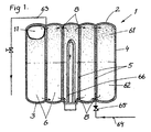
- FIG. 1 shows schematically an embodiment of water heater comprising a pressure vessel 1.
- the pressure vessel I includes a top dome 2 and a bottom dome 3 and an circumfering shell 4.
- the pressure vessel 1 contains a number of parting walls 5 stretching from one dome to the other along the shell 4, whereby a number of cells 6 is formed in the pressure vessel 1.
- the walls 5 are provided with adapted openings 8 placed were the walls 5 are connected with the gables 2, 3.
- a communication between the cells is hereby obtained.
- the thermally propelled circulation that normally occurs in a pressure vessel will be reduced by means of the walls 5, wherein a thermocline-like parting of the water with a warm upper zone 61 and a cold lower zone 62 will be formed during the heating of cold water.
- the heating time for parts of the water will hereby be reduced.
- a reduced amount of hot water can hereby be received before the total contained volume of water is heated to the desired temperature, by placing an outlet 63 in the top of the pressure vessel I where the hot water will accumulate.
- Cold water is supplied in the bottom of the pressure vessel 1 through an inlet 64 by a clack valve 65 which automatically opens when the pressure within the pressure vessel 1 falls under a predetermined level, which level is lower than the pressure of the water distribution system.
- the pressure vessel 1 is provided with a heater 66 which provides for the heating of the water.
- the heating of the water is achieved through convection where the surface of the heater 66 which is in contact with the water holds a temperature calculated as the temperature of the water plus 10 to 20°C while the heater is on.
- the pressure vessel 1 is further provided with an air- and water-tight elastic bladder 11 placed in one of the cells 6 to reduce negative effects of sudden pressure shocks in the water distribution system as well as the expansion of water when heated.
- This bladder 11 has been filled with a gas at a pressure adapted to the normal working pressure of the water heater.
- a pressure/volume levelling function is achieved when the pressure in the vessel 1 is increased due to temperature related expansion of the water.
- thermocline-like parting can be regulated so that the differences in temperature between the top and the bottom of the vessel can be increased and decreased respectively.
- the intensity of the thermocline-like parting is also depending of the thermal conductivity of the walls of the vessel. It is therefore possible to achieve greater differences in water temperature between top and bottom when the vessel is made of a plastic material since the thermal conductivity of plastic is low.
- the water in the cell 6 which contains the heater 66 will become sufficiently hot before the other cells 6 if the openings 8 are made sufficiently small.
- the outlet 63 is hereby suitably placed in connection to the cell 6 in which the heater 66 is located.
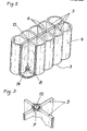
- FIG. 2 shows an embodiment of a lower vessel end part of a pressure vessel I for a water heater.
- the pressure vessel 1 comprises an upper vessel end part not shown which includes a dome 2 and a circumfering shell 4.
- the lower vessel end part comprises a dome 3 and a circumfering shell 4.
- the pressure vessel 1 contains a number of parting walls 5 wherein a number of cells 6 are formed in the pressure vessel 1. Matched openings 8 are placed between the different cells 6 at the point where the walls 5 join with the domes 2, 3. A communication between the cells 6 is hereby achieved.
- a number of crossing areas 7 (fig. 3) are formed where the walls 5 intersect with each other.
- the crossing areas 7 are provided with a tube-like channel 13 which runs parallel to and the full length of the walls and which constitutes the centre of the cross-section of the crossing area 7 (fig. 3). Two such pressure vessel halves can be joined together in whereby a pressure vessel 1 is formed.
- a suitable method for joining such pressure vessel end parts manufactured from thermoplastic material is thermal or chemical confounding, e.g. welding.
- Figure 3 shows a part of a crossing area 7 between two intersecting walls 5.
- a channel 13 is placed at the centre of the crossing area 7.
- FIGs 4 - 8 show different processes for the manufacturing of a pressure vessel 1.
- pressure vessel 1 from a thermoplastic material manufactured, pressure vessel 1 comprises two vessel end parts and a number of interconnecting and thereby load distributing walls 5 between which a number of cells 5 are formed.
- the walls 5 are placed so that a number of crossing areas 7 are formed between intersecting or connecting walls 5.
- the crossing areas 7 are provided with a termination by means of peg-like parts 31 (fig. 6) placed in one half of a mould 30 (fig. 6).
- Holes 14 (fig. 4 and 5) with an area larger than the crossing area 7 and with a depth greater than the thickness of the walls in the domes 2, 3 are hereby formed from the outside of the vessel.
- a channel 13 (fig.
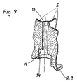
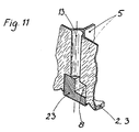
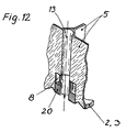
- Figures 9 - 13 show in cross-section a hole 14 placed in at least one of the domes 2, 3, different plugs and different ways to attach the plugs.
- the holes 14 (fig. 9) which are placed in the domes 2, 3, are provided with channel connection plugs 20 (fig. 12) which connects to a channel 13, main connection plugs 21 (fig. 12), blind plugs 22 (fig. 10) or closing plugs 23 (fig. 11).
- Inlet and outlet from the top or the bottom of the vessel can hereby be chosen regardless if the outer connections are placed at the top or the bottom of the pressure vessel 1.
- the holes 14 can further be closed without closing the openings 8, or a chosen part of an opening 8 can be closed so that one or more cells 6 (fig. 2) are separated from each other. All plugs can advantageously be attached by means of a friction welding method where for example rotational friction welding is specially suitable, however ultra-sonic welding is preferred for the closing plug 23 since this is non-symmetrical.
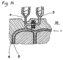
- FIG 14 shows in cross-section a process for the manufacturing of a pressure vessel 1 from two thermoplastic compositions in an inner and outer strata.
- the pressure vessel 1 is manufactured by injection moulding with two different thermoplastic compositions by injecting a first predetermined amount of molten thermoplastic material A into the mould cavity of the mould 30. A remaining second amount of a thermoplastic material B is thereafter injected into the cavity so that the thermoplastic material A in the main will enclose the thermoplastic material B.
- the thermoplastic material A is constituted by a pure polybutene without any filling or reinforcing material while the thermoplastic material B is constituted by polybutene mixed with an reinforcing material in the form of 15 % of carbon fibre.
- the thermoplastic material B can be constituted by a thermoplastic material mixed with 20 - 70 % of an electrically conductive material such as graphite nodules or conductive plastic material.
- the stratum constituted by the thermoplastic material B can hereby work as a heater by letting an electrical current flow through the material.
- the material will be self-adjusting since the thermal expansion in the thermoplastic part of stratum is relatively high.
- the resistance in the material will rise with increased temperatures since the graphite nodules will be parted from each other when the material expands. Needs of guiding electronics is hereby minimised or avoided.
- a water heater adapted to a variety of different temperature ranges and voltage ranges can be achieved.
- a first pressure vessel 1 according to the invention divided into 10 cells which were communicating by means of openings 8 according to figure 1 was compared to a second conventional pressure vessel without divisions.
- the two pressure vessels which each could contain a volume of 20 litres, were each provided with one immersion heater of 3 kW.
- the immersion heater of the pressure vessel according to the invention were placed in the middle cell 6 in one of the rows according to figure 1.
- the pressure vessels were also provided with a first temperature sensor close to the centre of the top dome 2, a second one close to the point were the top dome 2 meets the circumfering shell 4, a third one close to the centre of the bottom dome 3 and finally a fourth one close to the point were the bottom dome 3 meets the circumfering shell 4.
- the heater were then turned on and the temperature sensors were read at even time intervals.
- the temperatures were after 20 minutes 65°C and 64°C respectively at the two upper sensors of the vessel according to the invention.
- the temperatures at the same points of the other vessel were 58°C and 58°C respectively.
- the temperatures at the bottom of the vessel according to the invention were 32°C and 33°C respectively while the temperatures in the other vessel were 40°C and 41°C respectively.
- the comparison shows that the pressure vessel according to the invention gave a considerably faster heating time of the water in the upper part of the vessel.
- An extruded tube part for example, can be provided with two injection moulded dome parts.
- the dome parts can for example be held in position by a tensional strapping-like arrangement.
- Pressure vessels with a great height can hereby be achieved.
- a vessel with such a height will of cause also show greater differences in temperature between the top and the bottom during the heating phase of cold water which is a desired quality.
Landscapes
- Engineering & Computer Science (AREA)
- Mechanical Engineering (AREA)
- Manufacturing & Machinery (AREA)
- Combustion & Propulsion (AREA)
- Thermal Sciences (AREA)
- Chemical & Material Sciences (AREA)
- Physics & Mathematics (AREA)
- General Engineering & Computer Science (AREA)
- Lining Or Joining Of Plastics Or The Like (AREA)
- Pressure Vessels And Lids Thereof (AREA)
- Heat-Pump Type And Storage Water Heaters (AREA)
- Filling Or Discharging Of Gas Storage Vessels (AREA)
- Physical Water Treatments (AREA)
- Laminated Bodies (AREA)
Claims (18)
- Procédé destiné à la fabrication d'un récipient sous pression (1) constitué d'un matériau thermoplastique ou d'une résine thermodurcissable, ce récipient sous pression (1) comprenant une première partie et une deuxième partie d'extrémité du récipient fabriquées par moulage par injection ou par moulage à la presse et éventuellement une partie de tube intermédiaire qui est fabriquée de préférence par extrusion,
dans lequel les parties d'extrémités du récipient comprennent une enveloppe circonférentielle (4) qui forme les côtés du récipient sous pression (1) et chacune un dôme (2 ou 3) qui forme les parties supérieure et inférieure, respectivement, du récipient sous pression (1) lorsqu'ils sont raccordés,
dans lequel un certain nombre de parois d'interconnexion et de ce fait de répartition de la charge (5) s'étendent à partir des dômes (2, 3) le long de l'enveloppe circonférentielle (4) vers la partie ouverte de chaque partie d'extrémité du récipient,
qui, lorsque deux parties d'extrémité du récipient sont jointes, éventuellement avec un tube intermédiaire placé entre elles, les bords de chacune des parois (5) dans les différentes parties se rencontrent, un certain nombre de cellules (6) étant formé entre ces parois (5), et
dans lequel les parois (5) sont placées de telle manière qu'un certain nombre de zones de croisement (7) est formé entre des parois (5) qui se croisent ou qui se raccordent,
caractérisé en ce qu'un trou (14) est formé à partir de l'extérieur du dôme au niveau de la fin des zones de croisement (7), ce trou (14) étant plus gros que la zone de croisement (7) et présentant une profondeur supérieure à l'épaisseur de la partie de dôme (2, 3), de façon à former des ouvertures de communication (8) entre les cellules (6) dans le récipient sous pression (1). - Procédé selon la revendication 1,
caractérisé en ce que les parties d'extrémité du récipient et la partie de tube intermédiaire éventuelle sont jointes par soudage au miroir, soudage par friction, pressage ou collage. - Procédé selon la revendication 1 ou 2,
caractérisé en ce que les trous (14) sont façonnés au moyen de pièces semblables à des chevilles (31) placées dans une des moitiés d'un moule (30). - Procédé selon la revendication 3,
caractérisé en ce qu'une au moins des pièces semblables à des chevilles (31) qui est/sont placée(s) dans une des moitiés du moule et/ou en des points opposés de l'autre moitié du moule est/sont munie(s) d'un long noyau ou de longs noyaux (32) placé(s) dans l'axe dont la surface en section transversale est/sont inférieure(s) à la surface de la zone de croisement (7), d'où il résulte qu'un canal (13) au moins qui est parallèle aux parois (5) est formé dans la section transversale de la zone de croisement (7). - Procédé selon la revendication 3,
caractérisé en ce que les deux moitiés du moule (30) sont munies de moyens de réception (34), placés de manière axiale avec les pièces semblables à des chevilles (31), ces moyens de réception (34) étant destinés à recevoir un tube de préférence extrudé (15), ce tube étant fabriqué à partir d'une résine thermodurcissable ou d'un matériau thermoplastique, en ce que le tube (15) est placé dans la cavité de moule du moule (30), après quoi on injecte un matériau plastique fluent dans la cavité du moule pendant que le moyen de réception (34) empêche l'intrusion du matériau plastique dans le tube par l'intermédiaire d'un ajustement serré entre le moyen de réception (34) et les bords du tube (15). - Procédé selon la revendication 5,
caractérisé en ce qu'on injecte un gaz dans le tube (15) simultanément avec l'injection du matériau plastique de façon qu'une pression correspondant surtout à la pression du matériau plastique fluent injecté se forme à l'intérieur du tube (15), dans lequel on empêche le tube de s'affaisser sous l'influence de la pression d'injection du matériau plastique. - Procédé selon la revendication 3,
caractérisé en ce que les deux moitiés du moule (30) sont munies de moyens de réception (3, 4), placés de manière axiale avec les pièces semblables à des chevilles (31), ces moyens de réception (34) étant destinés à recevoir un profilé de noyau de fusion qui est placé dans le moule (30), après quoi on injecte un matériau plastique fluent dans la cavité du moule et en ce que le profilé de noyau de fusion est enlevé par fusion après avoir laissé le matériau plastique se solidifier et enlèvement de la pièce à partir du moule, d'où il résulte qu'un canal au moins qui est parallèle aux parois (5) est formé dans la section transversale de la zone de croisement (7). - Procédé selon la revendication 3,
caractérisé en ce qu'une quantité prédéterminée de matériau plastique fluent est injectée dans la cavité du moule, ce matériau plastique étant laissé se solidifier quelque peu, après quoi on injecte un gaz dans le matériau plastique par l'intermédiaire des pièces semblables à des chevilles (31) ou des points opposés dans l'autre moitié du moule (30), dans lequel un canal (13) au moins qui est parallèle aux parois est formé dans la section transversale de la zone de croisement (7). - Procédé selon l'une quelconque des revendications 1 à 8,
caractérisé en ce que les trous (14) sont munis de bouchons sélectionnés dans le groupe constitué d'un bouchon aveugle (22), d'un bouchon de raccordement de canal (20) raccordé aux canaux (13), d'un bouchon de raccordement principal (21) raccordé directement au récipient sous pression (1) ou d'un bouchon de fermeture (23) adapté pour limiter ou interrompre l'écoulement dans les ouvertures de communication (8), ces bouchons étant collés, vissés, soudés par friction, soudés au miroir ou pressés dans les trous (14) des dômes (2, 3). - Procédé selon l'une quelconque des revendications 1 à 9,
caractérisé en ce que les deux parties d'extrémités du récipient et la partie de tube intermédiaire éventuelle sont fabriquées par l'intermédiaire du moulage par injection de deux compositions, de préférence thermoplastiques, en injectant une première quantité prédéterminée d'un matériau plastique fluent A dans la cavité du moule, après quoi on injecte une deuxième quantité restante d'un matériau plastique fluent B, de façon que le matériau plastique A entoure dans l'ensemble le matériau plastique B. - Procédé selon la revendication 10,
caractérisé en ce que le matériau plastique A est un matériau plastique pur, non chargé, sélectionné parmi le polypropylène, le polybutylène, le polyamide, le polycarbonate, le polytérephtalate d'alkylène, le polychlorure de vinyle, le polystyrène, le polyéthylène réticulé ou similaire et en ce que le matériau plastique B est un des matériaux ci-dessus, de préférence le même que le matériau A, mélangé avec 1 à 3% d'un matériau sélectionné parmi la fibre de verre, la fibre de carbone, la fibre d'acier, le mica, la chaux ou similaire. - Procédé selon la revendication 10,
caractérisé en ce que le matériau plastique A est un matériau plastique pur, non chargé, sélectionné parmi le polyéthylène, le polypropylène, le polybutylène, le polyamide, le polycarbonate, le polytérephtalate d'alkylène, le polychlorure de vinyle, le polystyrène, le polyéthylène réticulé ou similaire et en ce que le matériau plastique B est un des matériaux ci-dessus, de préférence le même que le matériau A, mélangé avec 20 à 70% d'un matériau électriquement conducteur, sélectionné parmi les nodules de graphite, la fibre de carbone, la fibre d'acier ou similaire et ce que la couche formée par le matériau plastique B est connectée à un conducteur électrique de façon qu'un courant circule à travers la couche, d'où il résulte que la couche fonctionne comme élément chauffant. - Récipient sous pression (1) fabriqué par un procédé selon l'une quelconque des revendications 1 à 12, en particulier un récipient sous pression (1) pour un chauffe-eau, le récipient sous pression (1) comprenant deux dômes (2, 3) qui forment l'extrémité supérieure et l'extrémité inférieure du récipient sous pression (1) et une enveloppe circonférentielle (4) qui forme les côtés du récipient sous pression (1) et le récipient sous pression (1) contenant de plus un certain nombre de parois (5) de cloisonnement et de répartition de la charge s'étendant à partir d'un dôme (2) jusqu'à l'autre dôme (3) le long de l'enveloppe circonférentielle (4), dans lequel un certain nombre de cellules (6) est formé dans le récipient sous pression (1),
caractérisé en ce que les ouvertures (8) sont placées dans la zone où les parois (5) se raccordent aux dômes (2, 3) de façon que les ouvertures forment une communication entre les cellules (6), que la circulation thermique qui se produit normalement soit réduite au moyen des parois (5), d'où il résulte qu'une séparation de l'eau semblable à une thermocline avec une zone supérieure chaude (61) et une zone inférieure froide (62) est formée dans le récipient sous pression (1) pendant la phase de chauffage de l'eau froide. - Récipient sous pression (1) selon la revendication 13,
caractérisé en ce qu'une des cellules (6) au moins est munie d'une vessie (11) étanche à l'air et à l'eau qui contient un gaz à une pression prédéterminée, cette pression étant adaptée à la pression de service du récipient sous pression (1), dans lequel est reçue une fonction de nivellement pression/volume qui minimise les effets de la dilatation thermique de l'eau, des chocs de pression ou similaires. - Récipient sous pression (1) selon la revendication 13,
caractérisé en ce qu'une des cellules (6) au moins est munie d'ouvertures (8) au niveau de l'extrémité inférieure du récipient (1) seulement, dans lequel une cavité de gaz de nivellement de la pression est formée dans la cellule ou les cellules (6). - Récipient sous pression (1) selon l'une quelconque des revendications 13 à 15, caractérisé en ce que le récipient sous pression (1) est fabriqué à partir d'une résine thermodurcissable sélectionnée à partir du groupe du polyester ou de la résine mélamine ou d'un matériau thermoplastique sélectionné à' partir du groupe du polyéthylène, du polypropylène, du polybutylène, du polyamide, du polycarbonate, du polytérephtalate d'alkylène, du polychlorure de vinyle, du polystyrène, du polyéthylène réticulé ou similaire.
- Récipient sous pression (1) selon l'une quelconque des revendications 13 à 16, caractérisé en ce qu'une au moins des zones de croisement (7) entre les parois qui s'entrecroisent (5) est munie d'un canal (13) qui passe parallèlement aux parois (5)et sur toute leur longueur.
- Récipient sous pression (1) selon l'une quelconque des revendications 13 à 17, caractérisé en ce que les trous (14) qui sont prévus dans les dômes (2, 3) sont munis de bouchons sélectionnés à partir du groupe constitué de bouchons aveugles (22), de bouchons de raccordement de canaux (20) raccordés aux canaux (13), de bouchons de raccordement principaux (21) raccordés directement au récipient sous pression (1) ou de bouchons de fermeture (23) adaptés pour limiter ou interrompre l'écoulement à travers les ouvertures de communication (8), d'où il résulte que l'on peut placer au choix l'écoulement vers le récipient sous pression (1) et à partir de lui au sommet ou au fond, que l'on peut fermer les trous (14) sans fermer les ouvertures (8) ou qu'on peut fermer ou limiter une partie d'une ouverture (8) de façon à séparer partiellement ou complètement une ou plusieurs cellules (6) les unes des autres.
Applications Claiming Priority (3)
| Application Number | Priority Date | Filing Date | Title |
|---|---|---|---|
| SE9602135 | 1996-05-31 | ||
| SE9602135A SE508117C2 (sv) | 1996-05-31 | 1996-05-31 | Förfarande för framställning av ett tryckkärl samt tryckkärl, särskilt för varmvattenberedare, framställt genom förfarandet |
| PCT/SE1997/000817 WO1997045250A1 (fr) | 1996-05-31 | 1997-05-20 | Procede servant a fabriquer un recipient de pression et recipient de pression, particulierement pour un dispositif de rechauffement d'eau, fabrique au moyen de ce procede |
Publications (2)
| Publication Number | Publication Date |
|---|---|
| EP0906185A1 EP0906185A1 (fr) | 1999-04-07 |
| EP0906185B1 true EP0906185B1 (fr) | 2002-11-13 |
Family
ID=20402807
Family Applications (1)
| Application Number | Title | Priority Date | Filing Date |
|---|---|---|---|
| EP97926313A Expired - Lifetime EP0906185B1 (fr) | 1996-05-31 | 1997-05-20 | Procede servant a fabriquer un recipient de pression et recipient de pression, particulierement pour un dispositif de rechauffement d'eau, fabrique au moyen de ce procede |
Country Status (11)
| Country | Link |
|---|---|
| US (1) | US6188840B1 (fr) |
| EP (1) | EP0906185B1 (fr) |
| JP (1) | JP4263243B2 (fr) |
| AT (1) | ATE227639T1 (fr) |
| AU (1) | AU3110597A (fr) |
| CA (1) | CA2255864C (fr) |
| DE (1) | DE69717102T2 (fr) |
| ES (1) | ES2182092T3 (fr) |
| NO (1) | NO312233B1 (fr) |
| SE (1) | SE508117C2 (fr) |
| WO (1) | WO1997045250A1 (fr) |
Families Citing this family (10)
| Publication number | Priority date | Publication date | Assignee | Title |
|---|---|---|---|---|
| EP1147346A1 (fr) * | 1999-01-21 | 2001-10-24 | Goitre, Tiziana | Chauffe-eau en plastique, autoporteur |
| DE19907508A1 (de) * | 1999-02-22 | 2000-08-24 | Hench Gmbh H | Rohrförmiges Spritzgußteil für Reinigungsgeräte |
| SE518211C2 (sv) * | 1999-12-15 | 2002-09-10 | Swep Int Ab | Varmvattenberedare omfattande en plattvärmeväxlare och en lagringsbehållare |
| FR2900719B1 (fr) * | 2006-05-02 | 2008-07-25 | Claude Somajini | Chauffe-eau plat |
| DE102009025386A1 (de) * | 2009-06-16 | 2010-12-23 | Rehau Ag + Co. | Speicher zur Aufnahme eines Fluids |
| ES2381484T3 (es) * | 2010-01-25 | 2012-05-28 | Soterna, S. Coop. | Depósito para la acumulación de agua bajo presión |
| FR2965898B1 (fr) * | 2010-10-11 | 2014-11-21 | Waterslim Holding Sarl | Chauffe-eau parallelepipedique a cloisons longitudinales trouees |
| ITBS20100035U1 (it) | 2010-10-13 | 2012-04-14 | Aldo Giovanni Massaroli | Dispositivo elettrico per la produzione di acqua calda |
| CN111376446A (zh) * | 2018-12-29 | 2020-07-07 | 北京绿里生态科技有限公司 | 六面相同的中空正方体产品模具设计方法 |
| US12054237B2 (en) * | 2020-03-06 | 2024-08-06 | The Boeing Company | Skinned cell structures and methods of producing the same |
Family Cites Families (14)
| Publication number | Priority date | Publication date | Assignee | Title |
|---|---|---|---|---|
| NL302301A (fr) * | 1962-12-24 | |||
| JPS525293Y1 (fr) * | 1969-04-14 | 1977-02-03 | ||
| GB2111663B (en) * | 1981-12-16 | 1986-03-26 | Ocean Phoenix Holdings Nv | Tank for the storage and transport of pressurised fluid |
| JPS5913949U (ja) * | 1982-07-19 | 1984-01-27 | アイシン精機株式会社 | 樹脂製圧力容器 |
| EP0134363A3 (fr) | 1983-09-13 | 1985-11-13 | Everlast Hot Water Systems (Proprietary) Limited | Récipient utilisé comme vase de pression dans un système à eau chaude |
| JPS61106823U (fr) * | 1984-12-20 | 1986-07-07 | ||
| FI74342C (fi) | 1985-12-17 | 1988-01-11 | Neste Oy | Expansionsanordning som placerats i en trycksatt vaetskeberedare. |
| JPS63137246U (fr) * | 1987-03-02 | 1988-09-09 | ||
| SE460631B (sv) * | 1987-05-22 | 1989-10-30 | Leif Nilsson | Eluppvaermd behaallare och anvaendning av densamma |
| DE4008026A1 (de) * | 1990-03-10 | 1991-09-12 | Otto Geb Kg | Druckausgleichsgefaess fuer wasserversorgungs- und heizungseinrichtungen aus gespritztem kunststoff und verfahren zu seiner herstellung |
| SE514327C2 (sv) * | 1991-12-23 | 2001-02-12 | Ingemar Falk | Tryckbehållare |
| JPH0712405A (ja) * | 1993-04-26 | 1995-01-17 | Mitsubishi Electric Corp | 貯湯タンク |
| US5927537A (en) * | 1994-08-08 | 1999-07-27 | Falk; Ingemar | Pressure container |
| SE510801C2 (sv) * | 1995-03-29 | 1999-06-28 | Perstorp Ab | Tryckkärl |
-
1996
- 1996-05-31 SE SE9602135A patent/SE508117C2/sv unknown
-
1997
- 1997-05-20 DE DE69717102T patent/DE69717102T2/de not_active Expired - Lifetime
- 1997-05-20 AT AT97926313T patent/ATE227639T1/de not_active IP Right Cessation
- 1997-05-20 CA CA002255864A patent/CA2255864C/fr not_active Expired - Fee Related
- 1997-05-20 ES ES97926313T patent/ES2182092T3/es not_active Expired - Lifetime
- 1997-05-20 US US09/194,694 patent/US6188840B1/en not_active Expired - Fee Related
- 1997-05-20 JP JP54215897A patent/JP4263243B2/ja not_active Expired - Fee Related
- 1997-05-20 WO PCT/SE1997/000817 patent/WO1997045250A1/fr not_active Ceased
- 1997-05-20 AU AU31105/97A patent/AU3110597A/en not_active Abandoned
- 1997-05-20 EP EP97926313A patent/EP0906185B1/fr not_active Expired - Lifetime
-
1998
- 1998-11-27 NO NO19985545A patent/NO312233B1/no unknown
Also Published As
| Publication number | Publication date |
|---|---|
| DE69717102T2 (de) | 2003-04-17 |
| SE9602135L (sv) | 1997-12-01 |
| JP2000511120A (ja) | 2000-08-29 |
| SE508117C2 (sv) | 1998-08-31 |
| NO985545L (no) | 1999-01-21 |
| SE9602135D0 (sv) | 1996-05-31 |
| NO312233B1 (no) | 2002-04-15 |
| ES2182092T3 (es) | 2003-03-01 |
| ATE227639T1 (de) | 2002-11-15 |
| CA2255864A1 (fr) | 1997-12-04 |
| JP4263243B2 (ja) | 2009-05-13 |
| US6188840B1 (en) | 2001-02-13 |
| NO985545D0 (no) | 1998-11-27 |
| EP0906185A1 (fr) | 1999-04-07 |
| CA2255864C (fr) | 2005-10-11 |
| AU3110597A (en) | 1998-01-05 |
| WO1997045250A1 (fr) | 1997-12-04 |
| DE69717102D1 (de) | 2002-12-19 |
Similar Documents
| Publication | Publication Date | Title |
|---|---|---|
| US6188840B1 (en) | Process for the manufacturing of a pressure vessel and a pressure vessel, especially for a water heater, made by the process | |
| US6787116B2 (en) | Overmolding insert for heat exchanger, process for manufacturing a heat exchanger, and heat exchanger produced thereby | |
| CA2185492C (fr) | Chauffe-eau a reservoir de plastique moule et methodes de fabrication correspondantes | |
| US4152578A (en) | Electric heating elements | |
| CA1279579C (fr) | Dispositif pour amortir un bruit d'aspiration | |
| GB1577650A (en) | Coupling and method for connecting two tubular members by welding | |
| JPS59192543A (ja) | 射出成形装置 | |
| JPH03130131A (ja) | 2つのプラスチック部品を相互に接続するための電気溶接素子 | |
| CN220379985U (zh) | 电热水器 | |
| AU683987B2 (en) | Tank connector construction | |
| US4874104A (en) | Hot water storage tank | |
| KR100512043B1 (ko) | 전기보일러 | |
| US6785466B1 (en) | Electric water heater having balanced wattage density water heating | |
| US20070212036A1 (en) | Non-metallic heating element for use in a fluid heater | |
| EP1044347B1 (fr) | Chauffe-eau en matiere plastique resistant a la pression | |
| EP0134363A2 (fr) | Récipient utilisé comme vase de pression dans un système à eau chaude | |
| AU603353B2 (en) | A method of and apparatus for moulding a thermoplastics member with a fusion pad | |
| CN222598028U (zh) | 具有非金属壳体和高分子涂层的发热芯的加热器和水池 | |
| WO1994013457A2 (fr) | Joint, procede de fixation d'un joint et procede de fixation de composants de joint | |
| US3963521A (en) | Leakproof bonding of storage battery components | |
| GB2136098A (en) | Hot water cylinders | |
| WO1986004186A1 (fr) | Couvercle pour accumulateur | |
| CN203050381U (zh) | 免钢衬塑料异型材及其内共挤出模头 | |
| CN216897843U (zh) | 热水器 | |
| KR102323356B1 (ko) | 인서트 사출을 통한 냉각 판넬과 플랜지 간의 결합 구조 |
Legal Events
| Date | Code | Title | Description |
|---|---|---|---|
| PUAI | Public reference made under article 153(3) epc to a published international application that has entered the european phase |
Free format text: ORIGINAL CODE: 0009012 |
|
| 17P | Request for examination filed |
Effective date: 19981124 |
|
| AK | Designated contracting states |
Kind code of ref document: A1 Designated state(s): AT BE CH DE DK ES FI FR GB GR IE IT LI LU MC NL PT SE |
|
| 17Q | First examination report despatched |
Effective date: 20010723 |
|
| GRAG | Despatch of communication of intention to grant |
Free format text: ORIGINAL CODE: EPIDOS AGRA |
|
| GRAG | Despatch of communication of intention to grant |
Free format text: ORIGINAL CODE: EPIDOS AGRA |
|
| GRAG | Despatch of communication of intention to grant |
Free format text: ORIGINAL CODE: EPIDOS AGRA |
|
| GRAH | Despatch of communication of intention to grant a patent |
Free format text: ORIGINAL CODE: EPIDOS IGRA |
|
| GRAH | Despatch of communication of intention to grant a patent |
Free format text: ORIGINAL CODE: EPIDOS IGRA |
|
| GRAA | (expected) grant |
Free format text: ORIGINAL CODE: 0009210 |
|
| AK | Designated contracting states |
Kind code of ref document: B1 Designated state(s): AT BE CH DE DK ES FI FR GB GR IE IT LI LU MC NL PT SE |
|
| PG25 | Lapsed in a contracting state [announced via postgrant information from national office to epo] |
Ref country code: LI Free format text: LAPSE BECAUSE OF FAILURE TO SUBMIT A TRANSLATION OF THE DESCRIPTION OR TO PAY THE FEE WITHIN THE PRESCRIBED TIME-LIMIT Effective date: 20021113 Ref country code: GR Free format text: LAPSE BECAUSE OF FAILURE TO SUBMIT A TRANSLATION OF THE DESCRIPTION OR TO PAY THE FEE WITHIN THE PRESCRIBED TIME-LIMIT Effective date: 20021113 Ref country code: FI Free format text: LAPSE BECAUSE OF FAILURE TO SUBMIT A TRANSLATION OF THE DESCRIPTION OR TO PAY THE FEE WITHIN THE PRESCRIBED TIME-LIMIT Effective date: 20021113 Ref country code: CH Free format text: LAPSE BECAUSE OF FAILURE TO SUBMIT A TRANSLATION OF THE DESCRIPTION OR TO PAY THE FEE WITHIN THE PRESCRIBED TIME-LIMIT Effective date: 20021113 Ref country code: BE Free format text: LAPSE BECAUSE OF FAILURE TO SUBMIT A TRANSLATION OF THE DESCRIPTION OR TO PAY THE FEE WITHIN THE PRESCRIBED TIME-LIMIT Effective date: 20021113 Ref country code: AT Free format text: LAPSE BECAUSE OF FAILURE TO SUBMIT A TRANSLATION OF THE DESCRIPTION OR TO PAY THE FEE WITHIN THE PRESCRIBED TIME-LIMIT Effective date: 20021113 |
|
| REF | Corresponds to: |
Ref document number: 227639 Country of ref document: AT Date of ref document: 20021115 Kind code of ref document: T |
|
| REG | Reference to a national code |
Ref country code: GB Ref legal event code: FG4D |
|
| REG | Reference to a national code |
Ref country code: CH Ref legal event code: EP |
|
| REG | Reference to a national code |
Ref country code: IE Ref legal event code: FG4D |
|
| REF | Corresponds to: |
Ref document number: 69717102 Country of ref document: DE Date of ref document: 20021219 |
|
| PG25 | Lapsed in a contracting state [announced via postgrant information from national office to epo] |
Ref country code: SE Free format text: LAPSE BECAUSE OF FAILURE TO SUBMIT A TRANSLATION OF THE DESCRIPTION OR TO PAY THE FEE WITHIN THE PRESCRIBED TIME-LIMIT Effective date: 20030213 Ref country code: PT Free format text: LAPSE BECAUSE OF FAILURE TO SUBMIT A TRANSLATION OF THE DESCRIPTION OR TO PAY THE FEE WITHIN THE PRESCRIBED TIME-LIMIT Effective date: 20030213 Ref country code: DK Free format text: LAPSE BECAUSE OF FAILURE TO SUBMIT A TRANSLATION OF THE DESCRIPTION OR TO PAY THE FEE WITHIN THE PRESCRIBED TIME-LIMIT Effective date: 20030213 |
|
| REG | Reference to a national code |
Ref country code: ES Ref legal event code: FG2A Ref document number: 2182092 Country of ref document: ES Kind code of ref document: T3 |
|
| ET | Fr: translation filed | ||
| PG25 | Lapsed in a contracting state [announced via postgrant information from national office to epo] |
Ref country code: LU Free format text: LAPSE BECAUSE OF NON-PAYMENT OF DUE FEES Effective date: 20030520 Ref country code: IE Free format text: LAPSE BECAUSE OF NON-PAYMENT OF DUE FEES Effective date: 20030520 |
|
| REG | Reference to a national code |
Ref country code: CH Ref legal event code: PL |
|
| PG25 | Lapsed in a contracting state [announced via postgrant information from national office to epo] |
Ref country code: MC Free format text: LAPSE BECAUSE OF NON-PAYMENT OF DUE FEES Effective date: 20030531 |
|
| PLBE | No opposition filed within time limit |
Free format text: ORIGINAL CODE: 0009261 |
|
| STAA | Information on the status of an ep patent application or granted ep patent |
Free format text: STATUS: NO OPPOSITION FILED WITHIN TIME LIMIT |
|
| 26N | No opposition filed |
Effective date: 20030814 |
|
| REG | Reference to a national code |
Ref country code: IE Ref legal event code: MM4A |
|
| REG | Reference to a national code |
Ref country code: GB Ref legal event code: 732E |
|
| REG | Reference to a national code |
Ref country code: ES Ref legal event code: PC2A |
|
| NLS | Nl: assignments of ep-patents |
Owner name: SCHOELLER ARCA SYSTEMS AB Effective date: 20070515 |
|
| PGFP | Annual fee paid to national office [announced via postgrant information from national office to epo] |
Ref country code: FR Payment date: 20110615 Year of fee payment: 15 Ref country code: ES Payment date: 20110524 Year of fee payment: 15 |
|
| PGFP | Annual fee paid to national office [announced via postgrant information from national office to epo] |
Ref country code: NL Payment date: 20110526 Year of fee payment: 15 Ref country code: GB Payment date: 20110527 Year of fee payment: 15 |
|
| PGFP | Annual fee paid to national office [announced via postgrant information from national office to epo] |
Ref country code: DE Payment date: 20110527 Year of fee payment: 15 Ref country code: IT Payment date: 20110521 Year of fee payment: 15 |
|
| REG | Reference to a national code |
Ref country code: NL Ref legal event code: V1 Effective date: 20121201 |
|
| GBPC | Gb: european patent ceased through non-payment of renewal fee |
Effective date: 20120520 |
|
| PG25 | Lapsed in a contracting state [announced via postgrant information from national office to epo] |
Ref country code: IT Free format text: LAPSE BECAUSE OF NON-PAYMENT OF DUE FEES Effective date: 20120520 |
|
| REG | Reference to a national code |
Ref country code: FR Ref legal event code: ST Effective date: 20130131 |
|
| REG | Reference to a national code |
Ref country code: DE Ref legal event code: R119 Ref document number: 69717102 Country of ref document: DE Effective date: 20121201 |
|
| PG25 | Lapsed in a contracting state [announced via postgrant information from national office to epo] |
Ref country code: NL Free format text: LAPSE BECAUSE OF NON-PAYMENT OF DUE FEES Effective date: 20121201 |
|
| PG25 | Lapsed in a contracting state [announced via postgrant information from national office to epo] |
Ref country code: FR Free format text: LAPSE BECAUSE OF NON-PAYMENT OF DUE FEES Effective date: 20120531 Ref country code: GB Free format text: LAPSE BECAUSE OF NON-PAYMENT OF DUE FEES Effective date: 20120520 |
|
| PG25 | Lapsed in a contracting state [announced via postgrant information from national office to epo] |
Ref country code: DE Free format text: LAPSE BECAUSE OF NON-PAYMENT OF DUE FEES Effective date: 20121201 |
|
| REG | Reference to a national code |
Ref country code: ES Ref legal event code: FD2A Effective date: 20130820 |
|
| PG25 | Lapsed in a contracting state [announced via postgrant information from national office to epo] |
Ref country code: ES Free format text: LAPSE BECAUSE OF NON-PAYMENT OF DUE FEES Effective date: 20120521 |