EP0906214B1 - Kupplungsvorrichtung zum verbinden eines zugfahrzeuges mit einem auflieger-anhänger und verfahren zum umbauen von kupplungsvorrichtungen - Google Patents
Kupplungsvorrichtung zum verbinden eines zugfahrzeuges mit einem auflieger-anhänger und verfahren zum umbauen von kupplungsvorrichtungen Download PDFInfo
- Publication number
- EP0906214B1 EP0906214B1 EP97928248A EP97928248A EP0906214B1 EP 0906214 B1 EP0906214 B1 EP 0906214B1 EP 97928248 A EP97928248 A EP 97928248A EP 97928248 A EP97928248 A EP 97928248A EP 0906214 B1 EP0906214 B1 EP 0906214B1
- Authority
- EP
- European Patent Office
- Prior art keywords
- kingpin
- sleeve
- coupling device
- coupling
- trailer
- Prior art date
- Legal status (The legal status is an assumption and is not a legal conclusion. Google has not performed a legal analysis and makes no representation as to the accuracy of the status listed.)
- Expired - Lifetime
Links
Images



Classifications
-
- B—PERFORMING OPERATIONS; TRANSPORTING
- B62—LAND VEHICLES FOR TRAVELLING OTHERWISE THAN ON RAILS
- B62D—MOTOR VEHICLES; TRAILERS
- B62D53/00—Tractor-trailer combinations; Road trains
- B62D53/04—Tractor-trailer combinations; Road trains comprising a vehicle carrying an essential part of the other vehicle's load by having supporting means for the front or rear part of the other vehicle
- B62D53/08—Fifth wheel traction couplings
- B62D53/0842—King pins
-
- B—PERFORMING OPERATIONS; TRANSPORTING
- B62—LAND VEHICLES FOR TRAVELLING OTHERWISE THAN ON RAILS
- B62D—MOTOR VEHICLES; TRAILERS
- B62D53/00—Tractor-trailer combinations; Road trains
- B62D53/04—Tractor-trailer combinations; Road trains comprising a vehicle carrying an essential part of the other vehicle's load by having supporting means for the front or rear part of the other vehicle
- B62D53/08—Fifth wheel traction couplings
- B62D53/0885—Comprising devices to limit or to compensate for wear or excessive play; Lubricating, shock absorbing, bearing devices, or the like
Definitions
- the invention relates to a coupling device for connecting of a towing vehicle with a semi-trailer, at a kingpin on the trailer and one on the towing vehicle
- Fifth wheel coupling with lock elements for positive and rotatable gripping of essentially rotationally symmetrical Surfaces of the kingpin are arranged, the surfaces being protected by an abrasion resistant thermal Coating are formed.
- a coupling device of the type mentioned above is made known from DE-A1-43 04 857.
- the invention further relates to a coupling device with a coupling saddle attached to the towing vehicle, the one interact with a kingpin of the semitrailer Wear ring and a locking hook, with the King pin surfaces of the wear ring coming into contact and the locking hook have an anti-friction layer.
- the invention further relates to a method for converting Coupling devices for connecting a towing vehicle with a semi-trailer, where a kingpin on the trailer and a fifth wheel on the towing vehicle Lock elements for positive and rotatable gripping of essentially rotationally symmetrical surfaces of the kingpin are arranged in a state in which a lubricant-free and thus maintenance-free operation of the coupling device is possible.
- a coupling caliper is arranged on the towing vehicle the top view is essentially horseshoe-shaped, so that a mouth in the rear direction of the towing vehicle shows. At the bottom of the mouth is a horseshoe-shaped one Part, the so-called wear ring. On both sides of the Wear ring there are lock parts, especially a so-called Lock hooks or locking hooks which initially, i.e. when the fifth wheel coupling is open, out of engagement with the jaw opening are.
- the trailer is located on the underside of the front end a downward-facing so-called kingpin that connects of towing vehicles and trailers pushed into the mouth opening until it comes into contact with the wear ring.
- the Lock parts are now brought into their closed position and embrace them the kingpin.
- the surfaces of the wear ring that come into contact with one another, of the lock hook and the kingpin one turn of the saddle pin in the clutch saddle. So far they are with rotationally symmetrical surfaces educated.
- DE 35 30 467 A1 proposes for a fifth wheel coupling the surfaces coming into contact with the kingpin the wear ring and the locking hook with to provide an anti-friction layer.
- an anti-friction layer a polytetrafluoroethylene (PTFE) material was used.
- the anti-friction layer consists more precisely of one PTFE-coated mesh that adheres to the surfaces in question the wear ring and the locking hook in one Milling the same is glued.
- PTFE also comes from other areas (coating of cookware, Iron soles) known excellent sliding and Has anti-adhesive properties
- PTFE offers practical no wear resistance to abrasive materials.
- anti-friction layers are made of hard Metal compounds such as titanium nitride for fifth wheels have been used, although the contact surfaces of the locking hook and wear ring protect against abrasion, however increase the abrasion of the kingpin to the same extent. This has the consequence that the kingpin with an anti-friction layer must be provided, but this requires considerable effort elevated.
- DE-A-37 28 090 is a completely maintenance-free Fifth wheel coupling known.
- the kingpin is held in a separable roller bearing, that opened when engaging the trailer and then in the Clutch position is closed again.
- the roller bearing is lubricant-free and allows the kingpin to rotate in the lock of the fifth wheel.
- thermal coating also in the area of the kingpin provided.
- This thermal coating consists of a thermally sprayed hard material layer, for example one ceramic oxide, in particular aluminum oxide or titanium oxide, on which a layer of lubricant, in particular polytetrafluoroethylene, is applied.
- Such coating systems are also known from other areas of technology, for example. the technology of coating printing press cylinders, from Frying pans and iron soles.
- Ceramic materials have the basic disadvantage that it is relatively brittle and therefore resistant to shock loads are sensitive. On the other hand, with fifth wheels considerable shock loads occur, especially if a trailer is coupled to a towing vehicle.
- the invention is therefore based on the object of a coupling device and a method of the type mentioned in that regard to continue training that both in newly manufactured, but also by converting fifth wheel couplings that are already in operation a completely lubricant-free and therefore maintenance-free Operation becomes possible.
- this object is achieved in that the surfaces through outer surfaces one on the kingpin seated and thermally coated sleeve formed be, the sleeve with inner surfaces rotatable on the Kingpin is arranged.
- the anti-friction layer is a carbon-based layer.
- the object underlying the invention is based on this Way completely solved.
- a floating one on the kingpin Sleeve is arranged, the surfaces of which are at least partially are thermally coated with an abrasion-resistant coating achieved a considerable increase in the contaminated areas. While namely in conventional coupling devices Wear ring and the lock hook only along each small, arcuate surface sections on the corresponding Surfaces of the kingpin are in accordance with the invention achieved that the entire inner surface of the Sleeve also forms a sliding pairing, so that the load per unit area becomes significantly lower.
- the invention is applicable to both Manufacturing of new coupling devices can be used as well when reconditioning coupling devices that are already in operation.
- the kingpin In the former case, the kingpin must be manufactured in this way at the factory be that its outer circumference around the wall thickness of the Sleeve is smaller than this the standardized outer dimensions corresponds to a standard kingpin.
- the sleeve is on it roughen the outer surface.
- This measure has the advantage that between the sleeve and the coupling hook or the wear ring greater liability or friction is set as between the sleeve and the inside body of the kingpin.
- the sleeve then essentially turns on the body of the kingpin, so mostly on their inside that is protected and lies on the inside and less on its exposed outside relative to the wear ring and the coupling hook.
- the roughening is a Has a roughness depth that is greater than the thickness of the thermal Coating.
- Coupling device are the inner surfaces of the sleeve also thanks to an abrasion-resistant thermal coating educated.
- This measure has the advantage that the desired abrasion resistant Bearings in the same coating process can be applied simultaneously.
- the thermal Coating a carbon-based layer, in particular is a layer of essentially amorphous carbon.
- the sleeve is multi-shell in the circumferential direction.
- This measure has the advantage that simple assembly and possibly also disassembly of the sleeve on the kingpin in simple Way is possible. It must be taken into account that the kingpin, standardized according to DIN, has an axial area have a smaller diameter, that is, a constriction. You can therefore not slide a sleeve axially but must they rather in the radial direction on the Put on the kingpin.
- the sleeve is used in a group of embodiments double-skinned.
- a good effect is achieved with multi-layer sleeves, by having the sleeve on at least one of its axial ends a circumferential bevel tapering the sleeve towards its ends is provided, the sleeve axially by means of counter bevels is secured by fasteners.
- This measure has the advantage that radial emigration or even falling off the sleeve is impossible because the sleeve in radial direction is held positively.
- the fasteners can be at the free end of the kingpin as a lid and at the opposite end as a ring be trained.
- the ring is axially on the kingpin is slidably and axially supported on the kingpin, in particular by means of an O-ring.
- This measure has the advantage that a spring tension the sleeve is possible in the axial direction.
- the sleeve can therefore do not loosen up even if they are under constant alternating stress is exposed.
- the Sleeve formed in several parts in the axial direction.
- This measure has the advantage that the sleeve is mounted on the body is simplified since it is only pushed on axially must become.
- the kingpin comprises an axially divided body, one at the free end of the kingpin Lower part is removable and the several sleeves when removed Lower part can be pushed onto an upper part of the body are.
- This measure has the advantage that the sleeves both in reduced diameter area as well as in the upper area can be pushed on axially with a larger diameter.
- This measure has the advantage that an additional backup against an overload due to radial on the kingpin attacking forces is made possible.
- This measure has the advantage that the mentioned increase Strength with a relatively simple construction and therefore cheaper Manufacturing is possible.
- the lower part is screwed to the upper part. It is particularly preferred if the lower part with the Upper part is screwed via an axial threaded bolt.
- This measure has the advantage that simple assembly of the Kingpin is possible without resulting in disadvantages for result in its stability.
- Threaded bolt from a side of the King pin through the top and on his screwed free end to the lower part.
- the free end of the threaded bolt then preferably engages a threaded bore of a lower part at the free end of the Kingpin and pulls this against the upper part.
- This measure has the advantage that the threaded bolt is first fixed by axial pressing and then that Lower part screwed onto the threaded section of the threaded bolt that protrudes freely from the top.
- the sleeves have a different diameter and lie on axially opposite sides one pushed onto the body, essentially radially extending disc.
- This measure has the advantage that the entire outside in Appearance appearing surface in both its peripheral Areas as well as in a radial transition surface externally mounted components is shown. As a result, optimal surface properties can be found at all of the points mentioned to adjust.
- This measure has the advantage that with simple constructive Average axial bearing of the sleeve is achieved.
- the sleeve consists of hard metal. It is preferred on its for thermal coating provided surfaces are embossed polished. This leads to a mirror-bright surface on which the coating is special adheres well and in which it is ideally rotationally symmetrical after coating Surface there.
- the anti-friction layer can also be used on its own formed as a carbon-based layer.
- carbon-based layers i.e. Carbon containing or short carbon layers themselves due to an extremely high resistance to flow, by an extremely high hardness and yet by an extremely low friction on counterparts made of steel, for example.
- a carbon layer as an anti-friction layer on the one coming into contact with the kingpin Surfaces of the wear ring and the locking hook opens up the possibility of using lubricants to dispense with the kingpin entirely.
- PTFE which has good non-stick properties a carbon layer has the advantage that the latter itself is extremely hard and in contrast to a PTFE coating an additional hard material base layer can be dispensed with can.
- the is carbon-based Layer of amorphous structure.
- Amorphous carbon layers as an advantageous example have excellent for carbon-based layers Dry lubrication properties, so that on any use of lubricants can be dispensed with, which reduces environmental impact the fifth wheel coupling is greatly improved. Due to the property of acting as a dry lubricant, the amorphous carbon layer provides optimal wear protection for both the kingpin and the Wear ring and the locking hook without doing it yourself subject to wear because of the amorphous carbon layer still has a sufficiently high hardness. The amorphous Carbon layer is thus able to withstand the high To withstand surface pressure.
- the is carbon-based Layer a pure carbon layer of diamond-like structure.
- the Carbon layer and the surfaces an adhesion promoting layer arranged.
- the adhesive layers can be general sputtered metals such as aluminum, titanium or chrome consist.
- the carbon layer contains metal.
- metals can be advantageous the adhesion of amorphous carbon layers instead of through improved the use of an additional adhesive layer with another advantage is that metal-containing carbon layers with a higher Have the coating rate applied in a sputtering process.
- Metals can also use aluminum, titanium or chrome become.
- the carbon layer is in a layer deposition process, in particular a PECVD process, is applied.
- the carbon layer can be obtained by such processes on the one hand in thicknesses of particularly favorable for their hardness Apply a few microns, on the other hand, a good connection between the carbon layer and the steel body of the locking hook or the wear ring.
- the carbon layer preferably has a thickness of approximately 1 up to 20 ⁇ m.
- carbon layers have one such a thickness a very high hardness and sufficient Elasticity, which when used for a wear-free Clutch are optimal.
- Fig. 1 designates as a whole a kingpin arrangement.
- the arrangement 10 is not with its in Fig. 1 visible top on the underside of a semi-trailer attached, for example. With screws 12 through extend through an annular flange 13 of the arrangement 10.
- the kingpin 20 has an upper one Section 21, a middle section 22 and a lower one Section 23.
- the upper and lower sections 21, 23 have the same outside diameter, while the middle one Section 22 has a smaller diameter.
- the Sections 21, 22, 23 are via conical transitions 24, 25 connected to each other (see also Fig. 2).
- the dimensions of the kingpin 20 are standardized. In the Federal Republic of Germany, the standard DIN 74-080 is relevant.
- the kingpin 20 is on its surface with a sleeve 30 provided the entire circumferential surface of the kingpin 20 covered.
- the sleeve 30 is divided in two in the axial direction and consists of a first half-shell 31 and a second half-shell 32, each covering approximately 180 of the circumference of the kingpin 20. They are separated from one another by a seam 33.
- the two-shell Sleeve 30 held by a lid 34 which on the lower Section 23 screwed on by means of an axial screw 35 is.
- the left half-shell 31 of the sleeve 30 is in one piece.
- the enlarged section 39 shows is a wall 40 of the Sleeve 30 with an outer layer 41 and an inner Layer 42 provided.
- the layers 41 and 42 thus form an outer surface 45 and an inner surface 46 of FIG Sleeve 30.
- the outer surface 45 is thus the outer surface of the kingpin 20, while the inner surface 46 rests on a counter surface 47 of the kingpin body.
- the sleeve 30 thus represents a floating bearing, because on the one hand it is self-rotating along the sliding pairing of the surfaces 46/47 on the kingpin 20, and on the other hand, with its outer surface 45, represents an engagement surface for the lock elements of the fifth wheel coupling.
- the sleeve 30 is axially elastically braced on the kingpin 20.
- a ring 60 is provided for this purpose.
- the ring 60 is slightly in axially displaceable on the kingpin 20, such as indicated with a bearing 61.
- an O-ring 62 is between the ring 60 and A radial surface 63 of the flange 13, which acts elastically in the axial direction.
- the sleeve 30 is at its upper end in FIG. 2 with a Bevel 65 provided with which the sleeve 30 to her tapered free end.
- the cone angle of the bevel 65 can e.g. 45.
- the ring 60 has a complementary counter bevel 66 provided to which the bevel 65 positively invests.
- a slope 71 is provided which is form-fitting on a complementary shaped collar 70 on the outer periphery of the lid 34 is present.
- the sleeve 30 with its bevels 65, 71 is clamped axially and held in a form-fitting manner.
- the arrangement is such that the sleeve 30 can be easily assembled and disassembled on the king pin 10.
- slopes 75, 76 in the area of the transitions 24, 25 are designed, for example, with the maximum permissible taper angle of 6. Then, for example after removing the cover 34, the left half-shell 31 can be tilted outwards, as indicated by an arrow 78 in FIG. 2.
- the kingpin 20 compared to the standardized values with its diameters be dimensioned so that after putting on the Sleeve 30 the outer shape corresponds to the standard dimensions.
- the layers 41, 42 on both sides of the wall 40 of the sleeve 30 are preferably applied by thermal coating.
- the application of one is particularly preferred carbon-based layer, especially a layer that consists essentially of amorphous carbon.
- Such Layers are made in a so-called layer deposition process, in particular a PECVD process.
- the thickness of the layers 41, 42 is e.g. between 1 and 20 microns. This creates diamond-like carbon layers extremely high hardness of 3,000 HV, these layers besides this high hardness still have elasticity. this leads to in combination with their hardness to a very high wear resistance, both when engaging and normal Driving.
- Corresponding adhesive layers are also provided in layers 41, 42 that can generally be made of sputtered metallic Layers consist, for example, of aluminum, titanium or Chrome or alloys thereof.
- the surface of the sleeve 30 is preferably before the layers are embossed polished.
- embossing polishing the sleeve 30 is clamped in a rotating device and in applied with a polished diamond ball in the radial direction, the one with very little axial feed while rotating Sleeve is moved along the surface. there there is a process of displacement of material on the surface the sleeve 30, and ultimately there is almost a reflective surface.
- FIG. 3 is a variant of the embodiment according to Fig. 2 shown.
- a kingpin 80 in turn has an upper section 81, a middle section 82 and a lower section 83 on.
- the outer shape of the kingpin 80 corresponds thus essentially in accordance with that of the kingpin 20 1 and 2.
- the body of the kingpin 80 is a separate base 85, which has a frustoconical fit 86/87 is connected to an upper part 88 of the kingpin 80.
- Threaded bore 90 provided in the upper part 88.
- a threaded bolt 91 with a head 92 is through one with the threaded bore 90 aligned through hole 93 inserted in the head 92 and screwed into the threaded bore 90.
- the lower part 85 with the upper part 88 is axial screwed.
- the positive connection in the area of Fit 86/87 results in higher strength compared to radial ones Stresses at the free end of the kingpin 80.
- a first one radial circumferential shoulder 95 is provided at the foot of the fit 86 of the lower part 85 at the foot of the fit 86 of the lower part 85 .
- a second radial Circumferential shoulder 96 is located at the upper end in FIG. 3 of the middle section 82 on the upper part 88.
- the king pin 80 is with a first sleeve 100 as well a second sleeve 101 and an intermediate, in provided essentially in a radial plane ring 102.
- the first sleeve 100 is supported at the bottom on the first radial Circumferential shoulder 95 and above on the ring 102.
- the ring 102 again lies on the second radial circumferential shoulder 96 on.
- the second sleeve 101 is located on the top of the bottom over the upper part 88 projecting ring 102 on and lies further up on the third radial circumferential shoulder 97 on.
- the sleeves 100, 101 form the to the surfaces 26, 27 in the embodiment according to 1 and 2 corresponding treads.
- FIG. 3 is a section on a further enlarged scale also shown that an outer layer 103rd and an inner layer 104 on either side of the second Sleeve 101 (and of course in a corresponding manner on the first sleeve 100) are provided.
- the outer surface of the outer layer 103 is 107 and the inner surface of the inner layer 104 designated 108.
- the kingpin is then shortened and with one e.g. truncated cone-shaped recess corresponding to the Fit 87 provided. Finally, the kingpin turns 80 still provided with the central threaded bore 90.
- Fig. 4 shows yet another variant with some deviations compared to the embodiment shown in Fig. 3.
- a head 111 of a slightly conical threaded bolt 91a in a corresponding depression 113 in the Upper side 109 inserted.
- the upper part 88a of the kingpin 80a is with a correspondingly slightly conical through hole 115, as with an angle ⁇ of e.g. 1 indicated.
- the threaded bolt 91a is inserted into the conical through hole 115 axially pressed and the lower part 85a then screwed on.
- the material of the lower part 85a is only in weakened to the smallest possible extent, and you get a flat underside 125 of the lower part 85a.
- the roughness of the roughening 123 is preferably so dimensioned that the roughening also on the outer surface the thermal coating is effective.
- the Roughness depth for example, dimensioned larger than the thickness of the thermal Coating.
- the point of this measure is to put the sleeve on its outside with a higher coefficient of friction than on their inside. This ensures that the sleeve itself preferably on the inner surface relative to the body the kingpin while turning on its outer surface, without turning, on the wear ring or on the coupling hook is applied.
- the sleeve 30 or 100, 101 itself is preferably made of one Carbide made.
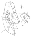
- 5 is one with the general reference numeral 110 shown coupling saddle, the part of a fifth wheel for connecting a tractor unit not shown here with a semitrailer trailer, not shown is.
- the clutch caliper 110 is on the top attached to the rear end of the tractor.
- the clutch caliper 110 has a horseshoe-shaped, of which Clutch caliper 110 removable wear ring 112 and a locking hook 114, which is clear in Fig. 5 shown separately from the clutch caliper 110 is.
- the locking hook 114 is normally pivotable attached to the clutch caliper 110.
- the clutch caliper 110 opens in the rearward direction with a mouth 116, at the bottom of which the wear ring 112 is arranged.
- the wear ring has a cylindrical section Surface 118 as a contact surface for one Kingpin not shown here, which in turn Is part of the tractor-trailer.
- the as an investment area serving surface 118 extends approximately to surface end sections 120 and 122 so that the surface 118 of the wear ring 112 the kingpin semicircular encloses.
- the locking hook 114 has one as a contact surface for the remaining circumference of the kingpin trained surface 120, which up to corresponding Surface end sections 124 and 126 are sufficient.
- the The king pin is inserted into the mouth 116 of the coupling saddle 110, until it is on the surface 118 of the wear ring 112 is applied. Then the swiveling on the corresponding one Locking hooks 114 fastened in place of the coupling saddle 110 pivoted so that it together with the wear ring 112th encloses the kingpin.
- the surface 120 of the Locking hook 114 and the surface 118 of the wear ring 112 form complementary to each other together an annular bearing of the kingpin, which in this storage is positively and rotatably received.
- the wear ring 112 consists of a base material 130, usually a tool steel.
- an adhesive layer 132 made of a metal, for example titanium, in sputtered with a thickness of about 1 ⁇ m.
- a carbon-based layer 134 of a thickness of approximately 10 ⁇ m in a layer deposition process, For example, a PECVD process (Plasma Enhanced Chemical Vapor Deposition).
- a PECVD process Pasma Enhanced Chemical Vapor Deposition
- Under carbon-based layers become pure carbon layers with diamond-like structure, metal-containing Carbon layers or amorphous carbon layers that are either pure or contain metal.
- the adhesion promoter layer 132 and the carbon-based one Layer 134 are on the entire surface 118 between the Surface end portions 120 and 122 are provided.
- the adhesive layer 132 may also be omitted.
- the locking hook is on a base material 136 114 an adhesive layer 138 and a carbon-based Layer 140, also about 10 in thickness ⁇ m, has been deposited.
Landscapes
- Engineering & Computer Science (AREA)
- Chemical & Material Sciences (AREA)
- Combustion & Propulsion (AREA)
- Transportation (AREA)
- Mechanical Engineering (AREA)
- Steering-Linkage Mechanisms And Four-Wheel Steering (AREA)
- Automobile Manufacture Line, Endless Track Vehicle, Trailer (AREA)
- Pivots And Pivotal Connections (AREA)
- Vehicle Body Suspensions (AREA)
- Regulating Braking Force (AREA)
- Agricultural Machines (AREA)
Description
- Fig. 1
- eine perspektivische Ansicht, von unten, auf eine Königszapfen-Anordnung;
- Fig. 2
- eine Seitenansicht des Königszapfens gemäß Fig. 1, in vergrößertem Maßstab und im Halbschnitt;
- Fig. 3
- eine Ansicht, ähnlich Fig. 2, jedoch für ein abgewandeltes Ausführungsbeispiel;
- Fig. 4
- eine weitere Ansicht, ähnlich Fig. 3, jedoch für ein weiter abgewandeltes Ausführungsbeispiel;
- Fig. 5
- einen Kupplungssattel einer Sattelkupplung mit einem dazugehörigen demontierten Verschlußhaken in perspektivischer Explosionsdarstellung;
- Fig. 6
- eine Draufsicht auf einen Verschleißring des Kupplungssattels;
- Fig. 7
- einen Schnitt entlang der Linie III-III aus Fig. 6;
- Fig. 8
- eine Draufsicht auf den Verschlußhaken; und
- Fig. 9
- einen Schnitt entlang der Linie V-V aus Fig. 8.
Die Hülse 30 stellt damit eine schwimmende Lagerung dar, weil sie einerseits entlang der Gleitpaarung der Oberflächen 46/47 auf dem Königszapfen 20 selbstdrehbar ist, andererseits mit ihrer äußeren Oberfläche 45 eine Eingriffsfläche für die Schloßelemente der Sattelkupplung darstellt.
Die Anordnung ist dabei so getroffen, daß die Hülse 30 auf dem Königszapfen 10 leicht montiert und demontiert werden kann. Hierzu sind Schrägen 75, 76 im Bereich der Übergänge 24, 25 z.B. mit dem maximal zulässigen Kegelwinkel von 6 ausgeführt. Dann kann z.B. nach Demontage des Deckels 34 die linke Halbschale 31 nach außen weggekippt werden, wie mit einem Pfeil 78 in Fig. 2 angedeutet.
Claims (12)
- Kupplungsvorrichtung zum Verbinden eines Zugfahrzeuges mit einem Auflieger-Anhänger, bei der an dem Anhänger ein Königszapfen (20; 80) und an dem Zugfahrzeug eine Sattelkupplung mit Schloßelementen zum formschlüssigen und drehbaren Ergreifen von im wesentlichen rotationssymmetrischen Oberflächen (26, 27; 105, 106) des Königszapfens (20; 80) angeordnet sind, wobei die Oberflächen (26, 27; 105, 106) durch eine abriebfeste thermische Beschichtung (41, 42; 103, 104) gebildet werden, dadurch gekennzeichnet, daß die Oberflächen (26, 27; 105, 106) durch äußere Oberflächen (45; 107) einer auf dem Königszapfen (20; 80) sitzenden und thermisch beschichteten Hülse (30; 100, 101) gebildet werden, wobei die Hülse (30; 100, 101) mit inneren Oberflächen (46; 108) drehbar auf dem Königszapfen (20; 80) angeordnet ist.
- Kupplungsvorrichtung nach Anspruch 1, dadurch gekennzeichnet, daß die Hülse (101a) auf ihrer äußeren Oberfläche (119) mit einer Aufrauhung (120) versehen ist, deren Rauhtiefe vorzugsweise größer ist als die Dicke der thermischen Beschichtung.
- Kupplungsvorrichtung nach Anspruch 1 oder 2, dadurch gekennzeichnet, daß die inneren Oberflächen (46; 108) ebenfalls durch eine abriebfeste thermische Beschichtung gebildet werden.
- Kupplungsvorrichtung nach einem oder mehreren der Ansprüche 1 bis 3, dadurch gekennzeichnet, daß die thermische Beschichtung eine kohlenstoffbasierte Schicht ist, insbesondere eine Schicht aus im wesentlichen amorphem Kohlenstoff ist.
- Kupplungsvorrichtung nach einem oder mehreren der Ansprüche 1 bis 4, dadurch gekennzeichnet, daß die Hülse (30) in Umfangsrichtung mehrschalig, insbesondere zweischalig ausgebildet ist.
- Kupplungsvorrichtung nach einem oder mehreren der Ansprüche 1 bis 4, dadurch gekennzeichnet, daß die Hülse (100, 101) in axialer Richtung mehrteilig ausgebildet ist.
- Kupplungsvorrichtung nach Anspruch 6, dadurch gekennzeichnet, daß der Königszapfen (80) einen axial mehrgeteilten Körper (85, 88) umfaßt, wobei ein am freien Ende des Königszapfens angeordnetes Unterteil (85) abnehmbar ist und die mehreren Hülsen (100, 101) bei abgenommenem Unterteil auf ein Oberteil (88) des Körpers (85, 88) aufschiebbar sind.
- Kupplungsvorrichtung nach einem oder mehreren der Ansprüche 1 bis 7, dadurch gekennzeichnet, daß die Hülsen (100, 101) einen unterschiedlichen Durchmesser aufweisen und auf axial entgegengesetzten Seiten an einer auf den Körper (85, 88) aufgeschobenen, sich im wesentlichen radial erstreckenden Scheibe (102) anliegen.
- Kupplungsvorrichtung nach Anspruch 7 oder 8, dadurch gekennzeichnet, daß die Hülsen (100, 101) durch Verschrauben der mehreren Teile des Körpers (85, 88) axial gehalten werden.
- Kupplungsvorrichtung, insbesondere nach einem oder mehreren der Ansprüche 1 bis 9, mit einem an dem Zugfahrzeug befestigten Kupplungssattel (110), der einen mit einem Königszapfen des Sattelanhängers zusammenwirkenden Verschleißring (112) und einen Verschlußhaken (114) aufweist, wobei mit dem Königszapfen in Anlage kommende Oberflächen (118, 124) des Verschleißringes (112) und des Verschlußhakens (114) eine Antifriktionsschicht aufweisen, dadurch gekennzeichnet, daß die Antifriktionsschicht eine kohlenstoffbasierte Schicht (134, 140) ist.
- Verfahren zum Umbauen von Kupplungsvorrichtungen für das Verbinden eines Zugfahrzeuges mit einem Auflieger-Anhänger, bei denen an dem Anhänger ein Königszapfen (20; 80) und an dem Zugfahrzeug eine Sattelkupplung mit Schloßelementen zum formschlüssigen und drehbaren Ergreifen von im wesentlichen rotationssymmetrischen Oberflächen des Königszapfens (20; 80) angeordnet sind, in einen Zustand, in dem ein schmiermittelfreier und damit wartungsfreier Betrieb der Kupplungsvorrichtung möglich ist, mit den Schritten:a) Abdrehen der Oberflächen des Königszapfens (20; 80) um ein vorbestimmtes Aufmaß;b) Herstellen einer Hülse (30; 100, 101) zum Aufsetzen auf den abgedrehten Königszapfen (20; 80), wobei die Wandstärke der Hülse (30; 100, 101) im wesentlichen gleich dem Aufmaß ist;c) Thermisches Beschichten mindestens der äußeren Oberfläche der Hülse (30; 100, 101) mit einer abriebfesten Beschichtung (41; 103); undd) Aufsetzen der Hülse (30; 100, 101) auf den abgedrehten Königszapfen (20; 80), derart, daß die Hülse (30; 100, 101) auf dem Königszapfen (20; 80) drehbar ist.
- Verfahren nach Anspruch 11, dadurch gekennzeichnet, daß der Königszapfen (80) zweigeteilt wird, derart, daß ein am freien Ende des Königszapfens (80) angeordnetes Unterteil (85) abnehmbar ist und daß die Hülse (100, 101) bei abgenommenem Unterteil (85) auf ein Oberteil (88) des Königszapfens (80) aufgeschoben wird, wobei vorzugsweise das Unterteil (85) nach dem Aufschieben der Hülse (100, 101) mit dem Oberteil (88) axial verschraubt und die Hülse (100, 101) damit axial gehalten wird.
Applications Claiming Priority (7)
| Application Number | Priority Date | Filing Date | Title |
|---|---|---|---|
| DE19624803 | 1996-06-21 | ||
| DE1996124803 DE19624803C2 (de) | 1996-06-21 | 1996-06-21 | Sattelkupplung |
| DE19644265 | 1996-10-24 | ||
| DE19644265 | 1996-10-24 | ||
| DE19647211 | 1996-11-15 | ||
| DE19647211A DE19647211C2 (de) | 1996-10-24 | 1996-11-15 | Kupplungsvorrichtung zum Verbinden eines Zugfahrzeuges mit einem Auflieger-Anhänger und Verfahren zum Umbauen von Kupplungsvorrichtungen |
| PCT/EP1997/003205 WO1997049600A1 (de) | 1996-06-21 | 1997-06-19 | Kupplungsvorrichtung zum verbinden eines zugfahrzeuges mit einem auflieger-anhänger und verfahren zum umbauen von kupplungsvorrichtungen |
Publications (3)
| Publication Number | Publication Date |
|---|---|
| EP0906214A1 EP0906214A1 (de) | 1999-04-07 |
| EP0906214B1 true EP0906214B1 (de) | 2002-02-13 |
| EP0906214B2 EP0906214B2 (de) | 2010-01-20 |
Family
ID=27216369
Family Applications (1)
| Application Number | Title | Priority Date | Filing Date |
|---|---|---|---|
| EP97928248A Expired - Lifetime EP0906214B2 (de) | 1996-06-21 | 1997-06-19 | Kupplungsvorrichtung zum verbinden eines zugfahrzeuges mit einem auflieger-anhänger und verfahren zum umbauen von kupplungsvorrichtungen |
Country Status (7)
| Country | Link |
|---|---|
| US (1) | US6220617B1 (de) |
| EP (1) | EP0906214B2 (de) |
| JP (1) | JP2000512592A (de) |
| AT (1) | ATE213209T1 (de) |
| AU (1) | AU3261597A (de) |
| ES (1) | ES2172797T5 (de) |
| WO (1) | WO1997049600A1 (de) |
Families Citing this family (11)
| Publication number | Priority date | Publication date | Assignee | Title |
|---|---|---|---|---|
| JP2005516849A (ja) * | 2002-02-11 | 2005-06-09 | ザ ホランド グループ,インコーポレイテッド | 潤滑油を少量だけ必要とする、または全く必要としない第5車輪ヒッチ |
| US7232767B2 (en) * | 2003-04-01 | 2007-06-19 | Mattson Technology, Inc. | Slotted electrostatic shield modification for improved etch and CVD process uniformity |
| US7147634B2 (en) | 2005-05-12 | 2006-12-12 | Orion Industries, Ltd. | Electrosurgical electrode and method of manufacturing same |
| US8814861B2 (en) | 2005-05-12 | 2014-08-26 | Innovatech, Llc | Electrosurgical electrode and method of manufacturing same |
| US7762167B2 (en) * | 2007-04-20 | 2010-07-27 | Lefebvre Richard M | Methods of modifying a trailer kingpin in situ |
| US7766361B2 (en) * | 2007-10-25 | 2010-08-03 | Saf-Holland, Inc. | Rotating fifth wheel hitch kingpin assembly |
| DE102010024843B4 (de) * | 2010-06-23 | 2012-05-31 | Patrick Kramer | Fahrzeug mit zumindest einem Kran |
| US9238390B2 (en) | 2012-07-03 | 2016-01-19 | Rel, Inc. | Composite articles, wear plates and methods |
| US9016708B2 (en) | 2013-05-14 | 2015-04-28 | Saf-Holland, Inc. | Fifth wheel hitch kingpin assembly |
| US8960704B2 (en) | 2013-05-14 | 2015-02-24 | Saf-Holland, Inc. | Fifth wheel hitch kingpin assembly |
| EP4300046A3 (de) | 2018-01-19 | 2024-06-19 | SAF-Holland, Inc. | Achszapfenbaugruppe mit kraftsensoranordnung |
Family Cites Families (18)
| Publication number | Priority date | Publication date | Assignee | Title |
|---|---|---|---|---|
| US2973210A (en) * | 1959-05-15 | 1961-02-28 | Bill Anderson Spring Service I | Kingpin assembly |
| US3870342A (en) * | 1973-01-11 | 1975-03-11 | Binkley Co | Retractable king pin and clamping assembly |
| US3894676A (en) * | 1973-10-15 | 1975-07-15 | Chemetron Corp | Method for construction of railway bolster |
| GB1582231A (en) | 1976-08-13 | 1981-01-07 | Nat Res Dev | Application of a layer of carbonaceous material to a surface |
| US4236863A (en) * | 1978-12-22 | 1980-12-02 | Dresser Industries, Inc. | Center pin assembly for power shovels |
| US4428595A (en) * | 1982-03-01 | 1984-01-31 | Holland Hitch Company | Fifth wheel hitch |
| US4478425A (en) * | 1982-10-21 | 1984-10-23 | Benko John M | Fifth wheel plate |
| US4592566A (en) * | 1984-07-09 | 1986-06-03 | Kyokuto Kaihatsu Kogyo Co, Ltd. | Coupling mechanism for king pin |
| DE3530467A1 (de) † | 1985-08-27 | 1987-03-05 | Walter Hunger | Sattelkupplung |
| JPS62127466A (ja) * | 1985-11-28 | 1987-06-09 | Toshiba Corp | セラミツクスが被着された部材 |
| CH674494A5 (de) * | 1987-10-08 | 1990-06-15 | Fischer Ag Georg | |
| US4828328A (en) * | 1988-05-03 | 1989-05-09 | Bowman Dan H | Replacement wheel bearing spindle |
| US4986923A (en) | 1989-06-27 | 1991-01-22 | Amoco Corporation | Front-wheel drive grease with synergistic sulfate and carbonate additive system |
| US5223161A (en) | 1989-06-27 | 1993-06-29 | Amoco Corporation | Extreme pressure and wear resistant grease with synergistic sulfate and carboxylate additive system |
| CH684575A5 (de) * | 1990-11-30 | 1994-10-31 | Roland Hauert Dr Manfred Roth | Verfahren zur Erniedrigung der Reibungskoeffizienten und Erhöhung des Verschleisswiderstandes eines auf festem Wasser gleitenden Körpers. |
| US5411281A (en) * | 1993-11-23 | 1995-05-02 | Poirier; Bertin | Fifth wheel construction having rotatable bearing plate |
| US5746438A (en) * | 1995-03-03 | 1998-05-05 | Jost--Werke AG | Fifth wheel |
| DE19637511A1 (de) * | 1996-09-13 | 1998-03-19 | Hunger Walter Dr Ing E H | Lagerelement einer Sattelkupplung, Sattelkupplung und Verfahren zum Herstellen eines Lagerelementes einer Sattelkupplung |
-
1997
- 1997-06-19 JP JP10502291A patent/JP2000512592A/ja active Pending
- 1997-06-19 ES ES97928248T patent/ES2172797T5/es not_active Expired - Lifetime
- 1997-06-19 AT AT97928248T patent/ATE213209T1/de not_active IP Right Cessation
- 1997-06-19 EP EP97928248A patent/EP0906214B2/de not_active Expired - Lifetime
- 1997-06-19 WO PCT/EP1997/003205 patent/WO1997049600A1/de not_active Ceased
- 1997-06-19 AU AU32615/97A patent/AU3261597A/en not_active Abandoned
- 1997-06-19 US US09/214,149 patent/US6220617B1/en not_active Expired - Lifetime
Also Published As
| Publication number | Publication date |
|---|---|
| ATE213209T1 (de) | 2002-02-15 |
| EP0906214A1 (de) | 1999-04-07 |
| ES2172797T3 (es) | 2002-10-01 |
| US6220617B1 (en) | 2001-04-24 |
| JP2000512592A (ja) | 2000-09-26 |
| AU3261597A (en) | 1998-01-14 |
| ES2172797T5 (es) | 2010-05-26 |
| WO1997049600A1 (de) | 1997-12-31 |
| EP0906214B2 (de) | 2010-01-20 |
Similar Documents
| Publication | Publication Date | Title |
|---|---|---|
| DE69303076T2 (de) | Lagereinheit für ein Fahrzeugrad | |
| EP0906214B1 (de) | Kupplungsvorrichtung zum verbinden eines zugfahrzeuges mit einem auflieger-anhänger und verfahren zum umbauen von kupplungsvorrichtungen | |
| DE1915932A1 (de) | Lagervorrichtung fuer ein Antriebsrad eines Motorfahrzeuges | |
| DE3143607C2 (de) | ||
| DE60112336T2 (de) | Radhalter für fahrzeuge mit scheibenbremsen | |
| DE3544222A1 (de) | Differentialachse fuer eisenbahnwagen | |
| DE69711500T2 (de) | Radnabenkonstruktion,insbesondere für ein Fahrzeug | |
| EP1155829A2 (de) | Austauschbare Zylinderelemente an elektrographischen Druckeinheiten | |
| EP1355075A2 (de) | Verbund-Bremsscheibe für eine Fahrzeug-Scheibenbremse | |
| DE19647211C2 (de) | Kupplungsvorrichtung zum Verbinden eines Zugfahrzeuges mit einem Auflieger-Anhänger und Verfahren zum Umbauen von Kupplungsvorrichtungen | |
| DE69129597T2 (de) | Radachse | |
| DE20319147U1 (de) | Radträgereinheit für ein Kraftfahrzeug | |
| EP1069334A1 (de) | Sicherungselement für Scheibenbremsklötze | |
| DE4304857C2 (de) | Sattelkupplung | |
| EP0121601B1 (de) | Bremszange für eine Scheibenbremse | |
| EP1756439B1 (de) | Zentralgelenk für einen dreieckslenker von kraftfahrzeugen | |
| EP0058732A1 (de) | Sattelkupplung | |
| WO2011069606A1 (de) | Radbaugruppe | |
| DE102004034565A1 (de) | Achsschenkel oder Radträger mit integriertem Bremsträger | |
| DE10057587A1 (de) | Radlagerung, insbesondere für Anhängerachsen | |
| DE19624803C2 (de) | Sattelkupplung | |
| DE19637511A1 (de) | Lagerelement einer Sattelkupplung, Sattelkupplung und Verfahren zum Herstellen eines Lagerelementes einer Sattelkupplung | |
| WO2004109141A1 (de) | Anordnung einer bremsscheibe an einer radnabe | |
| EP0507342B1 (de) | Sattelkupplung mit einer Schmiermittelversorgung für den Schlossbereich | |
| DE19836678C1 (de) | Radlagereinheit für ein angetriebenes Rad eines Kraftfahrzeuges |
Legal Events
| Date | Code | Title | Description |
|---|---|---|---|
| PUAI | Public reference made under article 153(3) epc to a published international application that has entered the european phase |
Free format text: ORIGINAL CODE: 0009012 |
|
| 17P | Request for examination filed |
Effective date: 19990114 |
|
| AK | Designated contracting states |
Kind code of ref document: A1 Designated state(s): AT CH DE ES FR GB IT LI NL SE |
|
| 17Q | First examination report despatched |
Effective date: 19990702 |
|
| GRAG | Despatch of communication of intention to grant |
Free format text: ORIGINAL CODE: EPIDOS AGRA |
|
| GRAG | Despatch of communication of intention to grant |
Free format text: ORIGINAL CODE: EPIDOS AGRA |
|
| GRAG | Despatch of communication of intention to grant |
Free format text: ORIGINAL CODE: EPIDOS AGRA |
|
| GRAH | Despatch of communication of intention to grant a patent |
Free format text: ORIGINAL CODE: EPIDOS IGRA |
|
| GRAH | Despatch of communication of intention to grant a patent |
Free format text: ORIGINAL CODE: EPIDOS IGRA |
|
| GRAA | (expected) grant |
Free format text: ORIGINAL CODE: 0009210 |
|
| REG | Reference to a national code |
Ref country code: GB Ref legal event code: IF02 |
|
| AK | Designated contracting states |
Kind code of ref document: B1 Designated state(s): AT CH DE ES FR GB IT LI NL SE |
|
| PG25 | Lapsed in a contracting state [announced via postgrant information from national office to epo] |
Ref country code: NL Free format text: LAPSE BECAUSE OF FAILURE TO SUBMIT A TRANSLATION OF THE DESCRIPTION OR TO PAY THE FEE WITHIN THE PRESCRIBED TIME-LIMIT Effective date: 20020213 |
|
| REF | Corresponds to: |
Ref document number: 213209 Country of ref document: AT Date of ref document: 20020215 Kind code of ref document: T |
|
| REG | Reference to a national code |
Ref country code: CH Ref legal event code: EP |
|
| REF | Corresponds to: |
Ref document number: 59706391 Country of ref document: DE Date of ref document: 20020321 |
|
| PG25 | Lapsed in a contracting state [announced via postgrant information from national office to epo] |
Ref country code: SE Free format text: LAPSE BECAUSE OF FAILURE TO SUBMIT A TRANSLATION OF THE DESCRIPTION OR TO PAY THE FEE WITHIN THE PRESCRIBED TIME-LIMIT Effective date: 20020513 |
|
| GBT | Gb: translation of ep patent filed (gb section 77(6)(a)/1977) |
Effective date: 20020517 |
|
| PG25 | Lapsed in a contracting state [announced via postgrant information from national office to epo] |
Ref country code: AT Free format text: LAPSE BECAUSE OF NON-PAYMENT OF DUE FEES Effective date: 20020619 |
|
| PG25 | Lapsed in a contracting state [announced via postgrant information from national office to epo] |
Ref country code: LI Free format text: LAPSE BECAUSE OF NON-PAYMENT OF DUE FEES Effective date: 20020630 Ref country code: CH Free format text: LAPSE BECAUSE OF NON-PAYMENT OF DUE FEES Effective date: 20020630 |
|
| NLV1 | Nl: lapsed or annulled due to failure to fulfill the requirements of art. 29p and 29m of the patents act | ||
| ET | Fr: translation filed | ||
| REG | Reference to a national code |
Ref country code: ES Ref legal event code: FG2A Ref document number: 2172797 Country of ref document: ES Kind code of ref document: T3 |
|
| PLBQ | Unpublished change to opponent data |
Free format text: ORIGINAL CODE: EPIDOS OPPO |
|
| PLBI | Opposition filed |
Free format text: ORIGINAL CODE: 0009260 |
|
| 26 | Opposition filed |
Opponent name: JOST-WERKE GMBH & CO. KG Effective date: 20021113 |
|
| PLAV | Examination of admissibility of opposition |
Free format text: ORIGINAL CODE: EPIDOS OPEX |
|
| PLBF | Reply of patent proprietor to notice(s) of opposition |
Free format text: ORIGINAL CODE: EPIDOS OBSO |
|
| REG | Reference to a national code |
Ref country code: CH Ref legal event code: PL |
|
| PLBF | Reply of patent proprietor to notice(s) of opposition |
Free format text: ORIGINAL CODE: EPIDOS OBSO |
|
| PLBB | Reply of patent proprietor to notice(s) of opposition received |
Free format text: ORIGINAL CODE: EPIDOSNOBS3 |
|
| PLBQ | Unpublished change to opponent data |
Free format text: ORIGINAL CODE: EPIDOS OPPO |
|
| PLAB | Opposition data, opponent's data or that of the opponent's representative modified |
Free format text: ORIGINAL CODE: 0009299OPPO |
|
| R26 | Opposition filed (corrected) |
Opponent name: JOST-WERKE GMBH & CO. KG Effective date: 20021113 |
|
| PLAB | Opposition data, opponent's data or that of the opponent's representative modified |
Free format text: ORIGINAL CODE: 0009299OPPO |
|
| PUAH | Patent maintained in amended form |
Free format text: ORIGINAL CODE: 0009272 |
|
| STAA | Information on the status of an ep patent application or granted ep patent |
Free format text: STATUS: PATENT MAINTAINED AS AMENDED |
|
| 27A | Patent maintained in amended form |
Effective date: 20100120 |
|
| AK | Designated contracting states |
Kind code of ref document: B2 Designated state(s): AT CH DE ES FR GB IT LI NL SE |
|
| REG | Reference to a national code |
Ref country code: ES Ref legal event code: DC2A Date of ref document: 20100326 Kind code of ref document: T5 |
|
| REG | Reference to a national code |
Ref country code: FR Ref legal event code: PLFP Year of fee payment: 20 |
|
| PGFP | Annual fee paid to national office [announced via postgrant information from national office to epo] |
Ref country code: GB Payment date: 20160621 Year of fee payment: 20 Ref country code: ES Payment date: 20160614 Year of fee payment: 20 |
|
| PGFP | Annual fee paid to national office [announced via postgrant information from national office to epo] |
Ref country code: FR Payment date: 20160627 Year of fee payment: 20 |
|
| PGFP | Annual fee paid to national office [announced via postgrant information from national office to epo] |
Ref country code: IT Payment date: 20160628 Year of fee payment: 20 Ref country code: DE Payment date: 20160723 Year of fee payment: 20 |
|
| REG | Reference to a national code |
Ref country code: DE Ref legal event code: R071 Ref document number: 59706391 Country of ref document: DE |
|
| REG | Reference to a national code |
Ref country code: GB Ref legal event code: PE20 Expiry date: 20170618 |
|
| PG25 | Lapsed in a contracting state [announced via postgrant information from national office to epo] |
Ref country code: GB Free format text: LAPSE BECAUSE OF EXPIRATION OF PROTECTION Effective date: 20170618 |
|
| REG | Reference to a national code |
Ref country code: ES Ref legal event code: FD2A Effective date: 20180508 |
|
| PG25 | Lapsed in a contracting state [announced via postgrant information from national office to epo] |
Ref country code: ES Free format text: LAPSE BECAUSE OF EXPIRATION OF PROTECTION Effective date: 20170620 |