EP0906232B1 - Bandförderer - Google Patents
Bandförderer Download PDFInfo
- Publication number
- EP0906232B1 EP0906232B1 EP97926336A EP97926336A EP0906232B1 EP 0906232 B1 EP0906232 B1 EP 0906232B1 EP 97926336 A EP97926336 A EP 97926336A EP 97926336 A EP97926336 A EP 97926336A EP 0906232 B1 EP0906232 B1 EP 0906232B1
- Authority
- EP
- European Patent Office
- Prior art keywords
- belt
- deflection rollers
- conveyor
- deflection
- main path
- Prior art date
- Legal status (The legal status is an assumption and is not a legal conclusion. Google has not performed a legal analysis and makes no representation as to the accuracy of the status listed.)
- Expired - Lifetime
Links
- 238000007514 turning Methods 0.000 description 8
- 230000007935 neutral effect Effects 0.000 description 4
- 238000005452 bending Methods 0.000 description 3
- 230000007704 transition Effects 0.000 description 3
- 239000003245 coal Substances 0.000 description 2
- 239000004568 cement Substances 0.000 description 1
- 230000001419 dependent effect Effects 0.000 description 1
- 239000000463 material Substances 0.000 description 1
- 238000012986 modification Methods 0.000 description 1
- 230000004048 modification Effects 0.000 description 1
- 230000000717 retained effect Effects 0.000 description 1
Images



Classifications
-
- B—PERFORMING OPERATIONS; TRANSPORTING
- B65—CONVEYING; PACKING; STORING; HANDLING THIN OR FILAMENTARY MATERIAL
- B65G—TRANSPORT OR STORAGE DEVICES, e.g. CONVEYORS FOR LOADING OR TIPPING, SHOP CONVEYOR SYSTEMS OR PNEUMATIC TUBE CONVEYORS
- B65G15/00—Conveyors having endless load-conveying surfaces, i.e. belts and like continuous members, to which tractive effort is transmitted by means other than endless driving elements of similar configuration
- B65G15/08—Conveyors having endless load-conveying surfaces, i.e. belts and like continuous members, to which tractive effort is transmitted by means other than endless driving elements of similar configuration the load-carrying surface being formed by a concave or tubular belt, e.g. a belt forming a trough
-
- B—PERFORMING OPERATIONS; TRANSPORTING
- B65—CONVEYING; PACKING; STORING; HANDLING THIN OR FILAMENTARY MATERIAL
- B65G—TRANSPORT OR STORAGE DEVICES, e.g. CONVEYORS FOR LOADING OR TIPPING, SHOP CONVEYOR SYSTEMS OR PNEUMATIC TUBE CONVEYORS
- B65G67/00—Loading or unloading vehicles
- B65G67/60—Loading or unloading ships
- B65G67/606—Loading or unloading ships using devices specially adapted for bulk material
-
- B—PERFORMING OPERATIONS; TRANSPORTING
- B65—CONVEYING; PACKING; STORING; HANDLING THIN OR FILAMENTARY MATERIAL
- B65G—TRANSPORT OR STORAGE DEVICES, e.g. CONVEYORS FOR LOADING OR TIPPING, SHOP CONVEYOR SYSTEMS OR PNEUMATIC TUBE CONVEYORS
- B65G2201/00—Indexing codes relating to handling devices, e.g. conveyors, characterised by the type of product or load being conveyed or handled
- B65G2201/02—Articles
Definitions
- the present invention relates to a belt conveyor comprising an endless and closed conveyor belt which is flexible essentially merely about axes which are parallel with the transverse direction of the belt, guide means for making part of the conveyor belt follow a substantially rectilinear main path, and a branch device which is movable along the main path, for branching the conveyor belt from the main path via two branch paths which are parallel with a branch line, directed transversely of the main path, respectively to and from an arm, which is pivotable in a plane transversely of the branch line.
- a belt conveyor of this type is known from e.g. US-A-5,465,830, said belt conveyor being intended for feeding out and feeding in goods within an elongated area beside the main path, the branch device comprising a tower movable along a long side of the elongated area and supporting an arm, the free end of which extends into the elongated area.
- An upper part of the tower, which also supports the arm, is rotatable about a vertical axis.
- Belt conveyors of this type are, among other things, used for loading and unloading ships moored alongside the quay, in which case the elongated area is the ship's hold. They are also used in other contexts, for instance for conveying coal to and from coal depots, in which case the depot is the elongated area.
- the conveyor belt employed is advantageously of the type described in, for instance, US-A-5,060,787, US-A-5,351,810 and US-A-5,400,899.
- the conveyor belt is designed to be bent, in its closed state, rather in the one than in the other direction about an axis parallel to its transverse direction.
- the conveyor belt should therefore be passed around a deflection roller with contact between one side of the belt, i.e. the pulling power take-up side, and the deflection roller.
- the conveyor belt should thus in this case be directed the same way (i.e. in the same direction) in the branch paths adjacent to the arm, which in the known belt conveyor has resulted in a greater height than is desirable for the tower and a neutral position for the arm, which neutral position is not located centrally in the operating area of the arm.
- the object of the present invention is to improve in these respects a belt conveyor of the type stated by way of introduction, while the conveyor belt is treated carefully while travelling in the belt conveyor.
- the branch device comprise two deflection rollers, which are offset in opposite directions transversely of the main path and the axes of which are each perpendicular to a deflection plane through the centre of the respective deflection rollers, said plane intersecting the main path and the respective branch paths at a distance from the first deflection rollers, a height reduction can be made, in practice corresponding to the distance required for turning the conveyor belt through 1/2-3/4 turn about its own longitudinal axis.
- the input and output runs of the conveyor belt are thus laterally redirected in opposite directions in the transition between the main path and the branch, such that the entire vertical movement in the branch, including the upwards and downwards running branch paths, can take place in an essentially common plane transversely of the main path. Moreover, the redirection takes place in points where the transverse direction of the belt is essentially vertical when the branch line is vertical. This prevents the conveyor belt from being laterally bent.
- the position of the first deflection rollers in the deflection plane is determined by a plane through the branch line essentially being tangent to the periphery of the first deflection rollers in the radial plane through the centre of the respective deflection rollers.
- the branch device suitably comprises two second deflection rollers, whose axes are parallel and located in the respective deflection planes adjacent to the intersection of the respective deflection planes with the branch line.
- This design makes it possible to fully prevent the belt from being bent laterally, i.e. in the belt's own plane, which is most important since such a bending may shorten the life of the conveyor belt to a most considerable extent. Also the stress on the belt caused by a turning thereof around its own longitudinal direction is reduced through the invention, but this stress affects the life of the belt very little as long as it is symmetrical around the centre line of the belt.
- the branch device further comprises two third deflection rollers, the axes of which are located in the intersection of the respective deflection planes with the main path. Seen from the third deflection rollers towards the respective first deflection rollers, the conveyor belt can be turned in opposite directions or in the same direction.
- the conveyor belt seen from the two second deflection rollers towards the respective first deflection rollers, is turned in opposite directions. This requires that the conveyor belt along the main path have its pulling power take-up side directed downwards and that it be turned in the same direction between the main path and the respective one of the third deflection rollers as between the respective one of these and the respective first deflection rollers.
- the invention creates conditions for the adjustment turnings necessary for the function to be distributed uniformly on the upward and downward runs of the conveyor belt.
- the required space in the vertical direction is halved compared with the case where the adjustment turnings are effected merely by means of one of the upward and downward runs.
- the invention creates conditions for the belt runs along the branch paths to be parallel with the underside facing the same direction, which halves the required space in the vertical direction for operational turning of the arm around a central or neutral position approximately in the centre of the operating area of the arm.
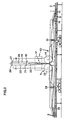
- Fig. 1 shows a conveying plant along a quay with an embodiment of a belt conveyor according to the invention.
- the belt conveyor comprises a conveyor belt 1 which is closed and endless, and a tower 2, which is movable back and forth along a main path 3 of the conveyor belt 1.
- the path of the conveyor belt 1 extends more specifically from a first deflection roller 4 along the main path 3 to the tower 2, up through the tower and out to a free end 5 of an arm 6 projecting from the tower 2, back from the end 5 of the arm 6 to the tower 2 and down through the tower, along the rest of the main path 3 to a second deflection roller 7 and along a return path 8 under the main path back to the first deflection roller 4.
- the tower is supported by a branch device 9, which comprises a frame 10, a so-called portal, which is movable on wheels for moving the tower 2 along the main path 3.
- the branch device 9 will be described in more detail below with reference to Figs 2 and 3.
- the conveyor belt 1 is supported by rollers 11 along the main path 3 and is raised from the main path by means of one or more rollers 12 mounted in the frame 10 and having a horizontal axis at one end of the frame 10.
- the conveyor belt 1 is passed from the rollers 12 in the same direction as the main path 3 towards the tower 2 during turning through about 90° about its longitudinal direction to at least one guide roller 13 having an essentially vertical axis, which is also mounted in the frame 10. From the guide roller 13 the conveyor belt 1 travels during continued turning through about further 90° to a deflection roller 14 having a slightly inclined axis, which is also mounted in the frame 10.
- the conveyor belt 1 follows a path, whose centre line 15 makes such an angle with the centre line 16 of the main path 3 that the deflection roller 14 is essentially located on one side of the centre line 16 of the main path 3.
- the belt After a deflection of about 90° around the deflection roller 14, the belt is passed in a branch direction 17 up to a guide roller 18 having a horizontal axis, which is also mounted in the frame 10. From the guide roller 18, the conveyor belt 1 travels vertically up along a branch path 19 through the tower 2 and further out in the arm 6, in whose free end 5 a feed-in or feed-out device can be mounted depending on whether loading or unloading is to be carried out.
- the upper part of the tower 2 is rotatable relative to the frame 10, which means that the conveyor belt 1 will be turned around its longitudinal direction along the branch path 19 when rotating the upper part of the tower 2 and, thus, the arm 6.
- the conveyor belt 1 then passes back from the free end 5 of the arm 6 into the tower 2 and down through the tower in a branch path 20 to the level of the guide roller 18, where a corresponding guide roller 21, whose axis is parallel to the axis of the guide roller 18, guides the conveyor belt 1 in a branch direction 22 down to a deflection roller 23 corresponding to the deflection roller 14 and further via guide rollers 24 and 25 corresponding to the guide rollers 13 and 12 out on the rest of the main path 3 in the direction of the second deflection roller 7.
- the conveyor belt 1 will, in its extent between the guide rollers 13, 18, not be subjected to any lateral bending since all parts of the conveyor belt 1 at the same distance from the centre line thereof will have the same distance to pass.
- Fig. 1 of a belt conveyor according to the present invention The preferred form of the path of the conveyor belt 1 in the embodiment shown in Fig. 1 of a belt conveyor according to the present invention is shown more clearly in Fig. 4, which merely illustrates the actual conveyor belt 1.
- Fig. 4 The positions of the different guide and deflection rollers, however, are indicated by arrows.
- the conveyor belt 1 may be of the type described in US-A-5,060,787, i.e. have a planar central part and two planar edge parts, which are each hingedly connected to the central part via a hinge part, the central part and the edge parts being flexurally rigid about the longitudinal direction of the conveyor belt and the combined width of the edge parts being greater than and the width of the hinge parts being essentially smaller than the width of the central part.
- the conveyor belt 1 can suitably be of the type described in US-A-5,351,810, i.e. equipped with a longitudinal strip which is fixedly connected to one side of the central part and projects upwards therefrom and which is located in the overlapping area of the edge parts, and, optionally, driver strips which are fixedly connected to the bottom part and the longitudinal strips and which extend from the longitudinal strip to at least one lateral edge of the central part.
- the conveyor belt 1 is of the type described in US-A-5,400,899, i.e. one of its edge parts is divided into two sections closest to its free longitudinal edge so as to form a longitudinal pocket which is open towards the free longitudinal edge and in which the free edge portion of the other edge part is received substantially non-rotatably and positively retained owing to the connection between the edge parts and the central part.
- the last-mentioned embodiment of the conveyor belt 1 is advantageous, in that e.g. no belt-guiding means are needed on the upper side of the conveyor belt 1 along its main path 3.
- the arm 6 could be designed so as to project on opposite sides of the tower, which may affect the best position of the conveyor belt 1 along the branch paths 19, 20.
- the conveyor belt 1 should, independently of its extent in the arm 6, be guided essentially parallel to the fixed guide rollers 18, 21 and deflection rollers 27, 28, which are mounted in the rotatable upper part of the tower 2.
- two or more deflection rollers may replace any deflection roller having a comparatively larger diameter, as illustrated in e.g. Fig. 2 in respect of the deflection rollers 12 and 25.
- the deflection rollers having the smaller diameter are then arranged along a curved path, preferably in the form of a circular arc, along which the conveyor belt is to travel.
Landscapes
- Engineering & Computer Science (AREA)
- Mechanical Engineering (AREA)
- Ocean & Marine Engineering (AREA)
- Aviation & Aerospace Engineering (AREA)
- Structure Of Belt Conveyors (AREA)
Claims (11)
- Ein Bandförderer, umfassend:dadurch gekennzeichnet, dassein endloses und geschlossenes Förderband (1), dass hauptsächlich nur über Achsen flexibel ist, die mit der Querrichtung des Bandes parallel sind,Führungsvorrichtungen (4, 7, 11), damit ein Teil des Förderbandes einen im Wesentlichen geradlinigen Hauptpfad (3) folgt, undeine Abzweigvorrichtung (9), die längs des Hauptpfades beweglich ist, zum Abzweigen des Förderbandes vom Hauptpfad über zwei Abzweigpfade (19, 20), die mit einer Abzweiglinie (26), die quer zum Hauptpfad gerichtet ist, parallel sind, zu bzw. von einem Arm (6), der in einer Ebene quer zur Abzweiglinie.verdrehbar ist,
die Abzweigvorrichtung (9) zwei erste Umlenkrollen (14, 23) umfasst, die in entgegengesetzter Richtung quer zum Hauptpfad (3) versetzt sind und deren Achsen sich jeweils senkrecht zu einer Umlenkebene durch die Mitte der jeweiligen Umlenkrollen befinden, wobei die Ebene den Hauptpfad und die jeweiligen Abzweigpfade (19, 20) in einem Abstand von den ersten Umlenkrollen schneidet. - Bandförderer nach Anspruch 1, dadurch gekennzeichnet, dass . die Lage der ersten Umlenkrollen (14, 23) in der Umlenkebene durch eine Ebene durch die Abzweiglinie (26) bestimmt wird, indem sie den Umfang der ersten Umlenkrollen in der radialen Ebene durch die Mitte der jeweiligen Umlenkrollen berühren.
- Bandförderer nach Anspruch 1 oder 2, gekennzeichnet durch zwei zweite Umlenkrollen (18, 21), deren Achsen parallel sind und die in den jeweiligen Umlenkebenen, dem Schnittpunkt der jeweiligen Umlenkebenen mit der Abzweiglinie (26) benachbart, angeordnet sind.
- Bandförderer nach Anspruch 3, dadurch gekennzeichnet, dass das Förderband (1), von den zwei zweiten Umlenkrollen (18, 21) in Richtung der jeweiligen ersten Umlenkrollen (14, 23) aus gesehen, in entgegengesetzte Richtungen gedreht wird.
- Bandförderer nach einem der Ansprüche 1 - 4, gekennzeichnet durch zwei dritte Umlenkrollen (13, 24), deren Achsen im Schnittpunkt der jeweiligen . Umlenkebenen mit dem Hauptpfad (3) und im Wesentlichen senkrecht zur . Querrichtung des Förderbandes (1) längs des Hauptpfades angeordnet sind.
- Bandförderer nach Anspruch 5, dadurch gekennzeichnet, dass die Achsen der dritten Umlenkrollen (13, 24) hauptsächlich vertikal sind.
- Bandförderer nach Anspruch 5 oder 6, dadurch gekennzeichnet, dass das Förderband (1), von den zwei dritten Umlenkrollen (13, 24) in Richtung der jeweiligen ersten Umlenkrollen (14, 23) aus gesehen, in entgegengesetzte Richtungen gedreht wird.
- Bandförderer nach Anspruch 5 oder 6, dadurch gekennzeichnet, dass das Förderband (1), von den zwei dritten Umlenkrollen (13, 24) in Richtung der jeweiligen ersten Umlenkrollen (14, 23) aus gesehen, in die gleiche Richtung gedreht wird.
- Bandförderer nach einem der Ansprüche 1 - 8, dadurch gekennzeichnet, dass die Abzweigvorrichtung (9) an der Seite gegenüber den jeweils dritten Umlenkrollen (13, 24) relativ zu den jeweils ersten Umtenkrollen (14, 23) eine vierte Umlenkrolle (12, 25) zum Abheben des Förderbandes (1) vom Hauptpfad (3) aufweist.
- Bandförderer nach einem der Ansprüche 1 - 9, dadurch gekennzeichnet, dass die Querrichtung des Förderbandes (1) in den Abzweigpfaden (19, 20) am nächsten zum-Hauptpfad (3), hauptsächlich parallel zur Längsrichtung des Hauptpfades ist.
- Bandförderer nach einem der Ansprüche 1 - 10, dadurch gekennzeichnet, dass mindestens eine der Umlenkrollen (14, 23; 18, 21; 13, 24; 12, 25) eine von mehreren Umlenkrollen ist, die längs eines gekrümmten Pfades, vorzugsweise in der Form eines Kreisbogens, angeordnet sind, über den sich das Förderband bewegen soll.
Applications Claiming Priority (3)
| Application Number | Priority Date | Filing Date | Title |
|---|---|---|---|
| SE9602127 | 1996-05-31 | ||
| SE9602127A SE9602127D0 (sv) | 1996-05-31 | 1996-05-31 | Bandtransportör |
| PCT/SE1997/000939 WO1997045343A1 (en) | 1996-05-31 | 1997-05-30 | Belt conveyor |
Publications (2)
| Publication Number | Publication Date |
|---|---|
| EP0906232A1 EP0906232A1 (de) | 1999-04-07 |
| EP0906232B1 true EP0906232B1 (de) | 2003-09-17 |
Family
ID=20402800
Family Applications (1)
| Application Number | Title | Priority Date | Filing Date |
|---|---|---|---|
| EP97926336A Expired - Lifetime EP0906232B1 (de) | 1996-05-31 | 1997-05-30 | Bandförderer |
Country Status (9)
| Country | Link |
|---|---|
| US (1) | US6021889A (de) |
| EP (1) | EP0906232B1 (de) |
| JP (1) | JP2000511145A (de) |
| AU (1) | AU716467B2 (de) |
| DE (1) | DE69724955T2 (de) |
| ES (1) | ES2207735T3 (de) |
| RU (1) | RU2175631C2 (de) |
| SE (1) | SE9602127D0 (de) |
| WO (1) | WO1997045343A1 (de) |
Families Citing this family (5)
| Publication number | Priority date | Publication date | Assignee | Title |
|---|---|---|---|---|
| EP1931585A4 (de) * | 2005-08-29 | 2008-09-24 | Rockwood Materials Handling In | Auf- und abtragsvorrichtung für luftkissenförderer und verfahren dafür |
| SI1948537T1 (sl) * | 2005-10-15 | 2009-12-31 | Flsmidth Koch Gmbh | Transportna naprava, posebno cevna transportna naprava |
| DE102008051162A1 (de) * | 2008-10-10 | 2010-04-15 | Liebherr-Mischtechnik Gmbh | Transportsystem |
| MX2013010888A (es) * | 2011-03-29 | 2013-12-06 | Smidth As F L | Dispositivo de transportacion y proceso de operacion del mismo. |
| CN110482245A (zh) * | 2019-08-15 | 2019-11-22 | 王静波 | 环保型多功能干散货港口及施工方法 |
Family Cites Families (9)
| Publication number | Priority date | Publication date | Assignee | Title |
|---|---|---|---|---|
| US3198353A (en) * | 1962-12-24 | 1965-08-03 | Mcdowell Wellman Eng Co | Bulk material loading system |
| FI76996C (fi) * | 1985-10-29 | 1989-01-10 | Kone Oy | Avlastningsanordning foer baot. |
| AU612761B2 (en) * | 1987-12-18 | 1991-07-18 | Lennart Tingskog | Belt conveyor |
| SE466597B (sv) * | 1990-12-28 | 1992-03-09 | Lennart Tingskog | Transportband |
| DE4125109C2 (de) * | 1991-07-30 | 1994-10-20 | Gutehoffnungshuette Man | Stetigfördernder Schiffsentlader für Schüttgüter |
| SE508610C2 (sv) * | 1991-10-22 | 1998-10-19 | Conveytech Holding Ab | Transportband samt detta utnyttjande transportör |
| DE4135467C2 (de) * | 1991-10-28 | 1994-05-11 | Gutehoffnungshuette Man | Aufhängung und Führung eines Senkrechtförderers im Entladerüssel eines Schiffsentladers |
| FR2687095B1 (fr) * | 1992-02-06 | 1995-06-09 | Vetrotex France Sa | Procede de fabrication d'un fil composite et produits composites obtenus a partir dudit fil. |
| SE470097B (sv) * | 1992-02-14 | 1993-11-08 | Lennart Tingskog | Transportör för in- eller utmatning av gods inom ett långsträckt område, vilken transportör innefattar ett enda ändlöst transportband |
-
1996
- 1996-05-31 SE SE9602127A patent/SE9602127D0/xx unknown
-
1997
- 1997-05-30 AU AU31125/97A patent/AU716467B2/en not_active Ceased
- 1997-05-30 EP EP97926336A patent/EP0906232B1/de not_active Expired - Lifetime
- 1997-05-30 JP JP09542241A patent/JP2000511145A/ja not_active Ceased
- 1997-05-30 RU RU98123605/03A patent/RU2175631C2/ru not_active IP Right Cessation
- 1997-05-30 ES ES97926336T patent/ES2207735T3/es not_active Expired - Lifetime
- 1997-05-30 WO PCT/SE1997/000939 patent/WO1997045343A1/en not_active Ceased
- 1997-05-30 DE DE69724955T patent/DE69724955T2/de not_active Expired - Fee Related
-
1998
- 1998-11-24 US US09/198,482 patent/US6021889A/en not_active Expired - Fee Related
Also Published As
| Publication number | Publication date |
|---|---|
| SE9602127D0 (sv) | 1996-05-31 |
| EP0906232A1 (de) | 1999-04-07 |
| DE69724955T2 (de) | 2004-07-15 |
| DE69724955D1 (de) | 2003-10-23 |
| AU3112597A (en) | 1998-01-05 |
| ES2207735T3 (es) | 2004-06-01 |
| AU716467B2 (en) | 2000-02-24 |
| JP2000511145A (ja) | 2000-08-29 |
| RU2175631C2 (ru) | 2001-11-10 |
| WO1997045343A1 (en) | 1997-12-04 |
| US6021889A (en) | 2000-02-08 |
Similar Documents
| Publication | Publication Date | Title |
|---|---|---|
| US5667054A (en) | Conveyor | |
| US4739876A (en) | Platform conveyor | |
| US4203512A (en) | Helical conveyor | |
| JPS6265811A (ja) | エレベ−タ又はコンベヤ装置 | |
| US4760908A (en) | Sorter conveyor | |
| US4917232A (en) | Flexible conveyor belt supporting structure | |
| US5657858A (en) | Conveyor | |
| JPH02147510A (ja) | コンベアシステムおよび物質運搬方法 | |
| EP0906232B1 (de) | Bandförderer | |
| KR920006689B1 (ko) | 선박에서의 하역 및 선적용 운반장치 | |
| CA2129740C (en) | Conveyor for loading and unloading material within a very wide area, which conveyor includes a single endless belt | |
| US5160012A (en) | Crane system with continual conveyor system for moving discrete items of freight | |
| KR0148587B1 (ko) | 이동 및 회전시 연속적인 재료의 공급이 가능한 회전 선교 재료 처리장치 | |
| USRE37747E1 (en) | Conveyer | |
| DE3660401D1 (en) | Transport installation | |
| EP0507413B1 (de) | Verteilerförderer | |
| US3442369A (en) | Suspended conveyor | |
| KR19980025011A (ko) | 특히 선박용으로서, 단위 하중의 연속적인 적하 및 하역용 디바이스 | |
| US5205399A (en) | Conveyor belt return training device | |
| US1192016A (en) | Loading apparatus. | |
| US2704148A (en) | Conveyor systems | |
| RU98123605A (ru) | Ленточный конвейер | |
| CA1149316A (en) | Elevator | |
| KR200155669Y1 (ko) | 벨트 컨베이어의 뒤집힘 방지장치 | |
| RU2041854C1 (ru) | Крановая установка с транспортной системой непрерывного действия для транспортирования штучных грузов |
Legal Events
| Date | Code | Title | Description |
|---|---|---|---|
| PUAI | Public reference made under article 153(3) epc to a published international application that has entered the european phase |
Free format text: ORIGINAL CODE: 0009012 |
|
| 17P | Request for examination filed |
Effective date: 19981126 |
|
| AK | Designated contracting states |
Kind code of ref document: A1 Designated state(s): BE CH DE ES FR GB IT LI NL |
|
| GRAH | Despatch of communication of intention to grant a patent |
Free format text: ORIGINAL CODE: EPIDOS IGRA |
|
| GRAS | Grant fee paid |
Free format text: ORIGINAL CODE: EPIDOSNIGR3 |
|
| GRAA | (expected) grant |
Free format text: ORIGINAL CODE: 0009210 |
|
| AK | Designated contracting states |
Kind code of ref document: B1 Designated state(s): BE CH DE ES FR GB IT LI NL |
|
| REG | Reference to a national code |
Ref country code: GB Ref legal event code: FG4D |
|
| REG | Reference to a national code |
Ref country code: CH Ref legal event code: EP |
|
| REF | Corresponds to: |
Ref document number: 69724955 Country of ref document: DE Date of ref document: 20031023 Kind code of ref document: P |
|
| RAP2 | Party data changed (patent owner data changed or rights of a patent transferred) |
Owner name: AS-C MATERIALS HANDLING LTD |
|
| NLT2 | Nl: modifications (of names), taken from the european patent patent bulletin |
Owner name: AS-C MATERIALS HANDLING LTD |
|
| REG | Reference to a national code |
Ref country code: CH Ref legal event code: NV Representative=s name: DR. LUSUARDI AG |
|
| PG25 | Lapsed in a contracting state [announced via postgrant information from national office to epo] |
Ref country code: GB Free format text: LAPSE BECAUSE OF NON-PAYMENT OF DUE FEES Effective date: 20040530 |
|
| PG25 | Lapsed in a contracting state [announced via postgrant information from national office to epo] |
Ref country code: LI Free format text: LAPSE BECAUSE OF NON-PAYMENT OF DUE FEES Effective date: 20040531 Ref country code: ES Free format text: LAPSE BECAUSE OF NON-PAYMENT OF DUE FEES Effective date: 20040531 Ref country code: CH Free format text: LAPSE BECAUSE OF NON-PAYMENT OF DUE FEES Effective date: 20040531 Ref country code: BE Free format text: LAPSE BECAUSE OF NON-PAYMENT OF DUE FEES Effective date: 20040531 |
|
| REG | Reference to a national code |
Ref country code: ES Ref legal event code: FG2A Ref document number: 2207735 Country of ref document: ES Kind code of ref document: T3 |
|
| ET | Fr: translation filed | ||
| PLBE | No opposition filed within time limit |
Free format text: ORIGINAL CODE: 0009261 |
|
| STAA | Information on the status of an ep patent application or granted ep patent |
Free format text: STATUS: NO OPPOSITION FILED WITHIN TIME LIMIT |
|
| 26N | No opposition filed |
Effective date: 20040618 |
|
| BERE | Be: lapsed |
Owner name: *AS-C MATERIALS HANDLING LTD Effective date: 20040531 |
|
| PG25 | Lapsed in a contracting state [announced via postgrant information from national office to epo] |
Ref country code: NL Free format text: LAPSE BECAUSE OF NON-PAYMENT OF DUE FEES Effective date: 20041201 Ref country code: DE Free format text: LAPSE BECAUSE OF NON-PAYMENT OF DUE FEES Effective date: 20041201 |
|
| REG | Reference to a national code |
Ref country code: CH Ref legal event code: PL |
|
| GBPC | Gb: european patent ceased through non-payment of renewal fee | ||
| PG25 | Lapsed in a contracting state [announced via postgrant information from national office to epo] |
Ref country code: FR Free format text: LAPSE BECAUSE OF NON-PAYMENT OF DUE FEES Effective date: 20050131 |
|
| NLV4 | Nl: lapsed or anulled due to non-payment of the annual fee |
Effective date: 20041201 |
|
| REG | Reference to a national code |
Ref country code: FR Ref legal event code: ST |
|
| PG25 | Lapsed in a contracting state [announced via postgrant information from national office to epo] |
Ref country code: IT Free format text: LAPSE BECAUSE OF NON-PAYMENT OF DUE FEES;WARNING: LAPSES OF ITALIAN PATENTS WITH EFFECTIVE DATE BEFORE 2007 MAY HAVE OCCURRED AT ANY TIME BEFORE 2007. THE CORRECT EFFECTIVE DATE MAY BE DIFFERENT FROM THE ONE RECORDED. Effective date: 20050530 |
|
| REG | Reference to a national code |
Ref country code: ES Ref legal event code: FD2A Effective date: 20040531 |