EP0906484B1 - Electric switch with static current monitoring - Google Patents
Electric switch with static current monitoring Download PDFInfo
- Publication number
- EP0906484B1 EP0906484B1 EP97931673A EP97931673A EP0906484B1 EP 0906484 B1 EP0906484 B1 EP 0906484B1 EP 97931673 A EP97931673 A EP 97931673A EP 97931673 A EP97931673 A EP 97931673A EP 0906484 B1 EP0906484 B1 EP 0906484B1
- Authority
- EP
- European Patent Office
- Prior art keywords
- safety
- closed circuit
- switching
- relay
- strip
- Prior art date
- Legal status (The legal status is an assumption and is not a legal conclusion. Google has not performed a legal analysis and makes no representation as to the accuracy of the status listed.)
- Expired - Lifetime
Links
- 238000012544 monitoring process Methods 0.000 title description 3
- 230000003068 static effect Effects 0.000 title 1
- 239000004020 conductor Substances 0.000 claims abstract description 5
- 230000001681 protective effect Effects 0.000 claims description 4
- 238000011156 evaluation Methods 0.000 description 3
- 238000010586 diagram Methods 0.000 description 2
- 238000009795 derivation Methods 0.000 description 1
- 239000002184 metal Substances 0.000 description 1
- 238000000926 separation method Methods 0.000 description 1
Images
Classifications
-
- F—MECHANICAL ENGINEERING; LIGHTING; HEATING; WEAPONS; BLASTING
- F16—ENGINEERING ELEMENTS AND UNITS; GENERAL MEASURES FOR PRODUCING AND MAINTAINING EFFECTIVE FUNCTIONING OF MACHINES OR INSTALLATIONS; THERMAL INSULATION IN GENERAL
- F16P—SAFETY DEVICES IN GENERAL; SAFETY DEVICES FOR PRESSES
- F16P3/00—Safety devices acting in conjunction with the control or operation of a machine; Control arrangements requiring the simultaneous use of two or more parts of the body
- F16P3/12—Safety devices acting in conjunction with the control or operation of a machine; Control arrangements requiring the simultaneous use of two or more parts of the body with means, e.g. feelers, which in case of the presence of a body part of a person in or near the danger zone influence the control or operation of the machine
-
- E—FIXED CONSTRUCTIONS
- E05—LOCKS; KEYS; WINDOW OR DOOR FITTINGS; SAFES
- E05F—DEVICES FOR MOVING WINGS INTO OPEN OR CLOSED POSITION; CHECKS FOR WINGS; WING FITTINGS NOT OTHERWISE PROVIDED FOR, CONCERNED WITH THE FUNCTIONING OF THE WING
- E05F15/00—Power-operated mechanisms for wings
- E05F15/40—Safety devices, e.g. detection of obstructions or end positions
- E05F15/42—Detection using safety edges
- E05F15/44—Detection using safety edges responsive to changes in electrical conductivity
- E05F2015/447—Detection using safety edges responsive to changes in electrical conductivity using switches in serial arrangement
-
- E—FIXED CONSTRUCTIONS
- E05—LOCKS; KEYS; WINDOW OR DOOR FITTINGS; SAFES
- E05Y—INDEXING SCHEME ASSOCIATED WITH SUBCLASSES E05D AND E05F, RELATING TO CONSTRUCTION ELEMENTS, ELECTRIC CONTROL, POWER SUPPLY, POWER SIGNAL OR TRANSMISSION, USER INTERFACES, MOUNTING OR COUPLING, DETAILS, ACCESSORIES, AUXILIARY OPERATIONS NOT OTHERWISE PROVIDED FOR, APPLICATION THEREOF
- E05Y2900/00—Application of doors, windows, wings or fittings thereof
- E05Y2900/10—Application of doors, windows, wings or fittings thereof for buildings or parts thereof
- E05Y2900/13—Type of wing
- E05Y2900/132—Doors
-
- H—ELECTRICITY
- H01—ELECTRIC ELEMENTS
- H01H—ELECTRIC SWITCHES; RELAYS; SELECTORS; EMERGENCY PROTECTIVE DEVICES
- H01H3/00—Mechanisms for operating contacts
- H01H3/02—Operating parts, i.e. for operating driving mechanism by a mechanical force external to the switch
- H01H3/14—Operating parts, i.e. for operating driving mechanism by a mechanical force external to the switch adapted for operation by a part of the human body other than the hand, e.g. by foot
- H01H3/141—Cushion or mat switches
- H01H2003/146—Cushion or mat switches being normally closed
-
- H—ELECTRICITY
- H02—GENERATION; CONVERSION OR DISTRIBUTION OF ELECTRIC POWER
- H02H—EMERGENCY PROTECTIVE CIRCUIT ARRANGEMENTS
- H02H5/00—Emergency protective circuit arrangements for automatic disconnection directly responsive to an undesired change from normal non-electric working conditions with or without subsequent reconnection
- H02H5/10—Emergency protective circuit arrangements for automatic disconnection directly responsive to an undesired change from normal non-electric working conditions with or without subsequent reconnection responsive to mechanical injury, e.g. rupture of line, breakage of earth connection
Definitions
- the invention relates to an electrical switching device according to the preamble of the main claim.
- Such electrical switching devices are such. B. in the EP 234 523 B1 described, in connection with a closing edge safety device.
- Such closing edge security systems are for use on motorized Doors and gates in buildings and public transport, movable shelves and on protective devices for machines intended. It flows into the actual safety edge Quiescent current, which is monitored by an evaluation unit. The Contact is established by interrupting the quiescent current. An automatic reset occurs after relief Closing the closed circuit.
- evaluation unit - or relay safety combination called - is also in the prior art known in various forms and constantly monitors itself in the Quiescent current principle. Errors, such as short-circuit cable break profile breaks and incorrect connection lead to shutdown the load circuits. Such are in the prior art Evaluation devices with the technical name "Relay-safety combination" designated.
- the invention has for its object a line monitoring to create both a simple earth fault shows how to react accordingly in the event of a short circuit.
- Such an arrangement is in connection with a closing edge safety device used, the or derivation of the closed circuit on a control signal that switching off the load circuits causes.
- EP-A-0 617 498 shows a grounded shield two-wire supply line to a consumer. A Transfer of this known protection technology to one with a Monitoring circuit operating in the closed circuit would have the Separation of the shielding in this case Supply and discharge required.
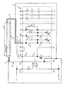
- a block diagram of a prior art safety relay combination type is in the system: "5983 BN" attached, in this block diagram, the shielding according to the invention is additionally located.
- 1 is the safety edge and 6 is the mounting edge shown for the safety edge 1, usually the mounting bar 6 is made of metal.
- the safety edge 1 lies above the mounting strip 6 the actual one Head 3, as known in the art.
- this conductor 3 is provided with a safety shield 5 surround, which ends at the earth potential of the Signal generator, d. H. according to the drawing on the fastening strip 6 of the safety edge 1 connects.
- the other end is that Safety shield 5 on a corresponding line the protective conductor connection PE (-) of the relay safety combination 2 connected, so that already at earth fault a shutdown of the supply or discharge of the closed circuit the load circuits is effected.
Landscapes
- Engineering & Computer Science (AREA)
- General Engineering & Computer Science (AREA)
- Mechanical Engineering (AREA)
- Emergency Protection Circuit Devices (AREA)
- Keying Circuit Devices (AREA)
- Control Of Motors That Do Not Use Commutators (AREA)
- Power Conversion In General (AREA)
- Dc-Dc Converters (AREA)
- Testing Electric Properties And Detecting Electric Faults (AREA)
Abstract
Description
Die Erfindung bezieht sich auf eine elektrische Schalteinrichtung gemäß dem Oberbegriff des Hauptanspruches.The invention relates to an electrical switching device according to the preamble of the main claim.
Derartige elektrische Schalteinrichtungen sind z. B. in der EP 234 523 B1 beschrieben, und zwar im Zusammenhang mit einer Schließkantensicherung. Derartige Schließkantensicherungssysteme sind für den Einsatz an motorisch betriebenen Türen und Toren in Gebäuden und öffentlichen Verkehrsmitteln, verfahrbaren Regalen und an Schutzeinrichtungen für Maschinen vorgesehen. In der eigentlichen Schaltleiste fließt ein Ruhestrom, der von einer Auswerteeinheit überwacht wird. Die Kontaktgabe erfolgt durch die Unterbrechung des Ruhestromes. Nach Entlastung tritt eine automatische Rückstellung zur Schließung des Ruhestromkreises ein.Such electrical switching devices are such. B. in the EP 234 523 B1 described, in connection with a closing edge safety device. Such closing edge security systems are for use on motorized Doors and gates in buildings and public transport, movable shelves and on protective devices for machines intended. It flows into the actual safety edge Quiescent current, which is monitored by an evaluation unit. The Contact is established by interrupting the quiescent current. An automatic reset occurs after relief Closing the closed circuit.
Die sogenannte Auswerteeinheit - oder auch Relaissicherheitskombination genannt - ist im Stand der Technik ebenfalls in vielfältiger Form bekannt und überwacht sich ständig selbst im Ruhestromprinzip. Fehler, wie Kurzschluß-Kabelbruch-Profilunterbrechungen und Falschanschluß führen zum Abschalten der Lastschaltkreise. Im Stand der Technik sind derartige Auswertegeräte mit der Fachbezeichnung "Relais-Sicherheitskombination" bezeichnet.The so-called evaluation unit - or relay safety combination called - is also in the prior art known in various forms and constantly monitors itself in the Quiescent current principle. Errors, such as short-circuit cable break profile breaks and incorrect connection lead to shutdown the load circuits. Such are in the prior art Evaluation devices with the technical name "Relay-safety combination" designated.
Bei diesen bekannten Anordnungen liegt der Nachteil vor, daß ein einseitiger Erdschluß nicht erkannt wird, da die Einrichtung weiterhin funktionsfähig bleibt.The disadvantage of these known arrangements is that a one-sided earth fault is not recognized because the device remains functional.
Der Erfindung liegt die Aufgabe zugrunde, eine Leitungsüberwachung zu schaffen, die sowohl einen einfachen Erdschluß aufzeigt wie auch bei Kurzschluß entsprechend reagiert.The invention has for its object a line monitoring to create both a simple earth fault shows how to react accordingly in the event of a short circuit.
Diese der Erfindung zugrundeliegende Aufgabe wird durch die Merkmale des kennzeichnenden Teiles des Hauptanspruches gelöst, d. h. dadurch, daß die elektrische Zu- und Ableitung des Ruhestromkreises zum Signalgeber je mit einem leitenden Sicherheitsschirm ummantelt sind, der einenendes an das Erdpotential des Signalgebers, z. B. an die Befestigungsleiste einer Schaltleiste anschließt und anderenendes an den Schutzleiteranschluß der Relaissicherheitskombination anschließt, wobei der Sekundärstromkreis des Transformators in der Relaissicherheitskombination einseitig mit dem Sicherheitsschirm verbunden ist.This object of the invention is achieved by Features of the characterizing part of the main claim solved, d. H. characterized in that the electrical supply and discharge of the Quiescent circuit to the signal generator each with a conductive safety shield are encased, the one that ends at the earth potential the signal generator, e.g. B. on the mounting strip Safety edge connects and the other end to the protective conductor connection connects the relay safety combination, whereby the secondary circuit of the transformer in the relay safety combination connected on one side to the safety shield is.
Wird eine solche Anordnung in Verbindung mit einer Schließkantensicherung eingesetzt, tritt schon bei Erdschluß der Zu- oder Ableitung des Ruhestromkreises ein Steuersignal auf, das ein Abschalten der Laststromkreise bewirkt.Such an arrangement is in connection with a closing edge safety device used, the or derivation of the closed circuit on a control signal that switching off the load circuits causes.
Die EP-A-0 617 498 zeigt eine geerdete Abschirmung einer zweidrahtigen Versorgungsleitung zu einem Verbraucher. Eine Übertragung dieser bekannten Schutztechnik auf eine mit einem Ruhestromkreis arbeitende Überwachungsschaltung hätte die Auftrennung der Abschirmung auf die in diesem Fall getrennten Zu- und Ableitung erforderlich gemacht. EP-A-0 617 498 shows a grounded shield two-wire supply line to a consumer. A Transfer of this known protection technology to one with a Monitoring circuit operating in the closed circuit would have the Separation of the shielding in this case Supply and discharge required.
Zur Verdeutlichung der Erfindung wird in der Anlage ein Blockschaltbild einer im Stand der Technik bekannten Relaissicherheitskombination Typ: "BN 5983" beigefügt, wobei in dieses Blockschaltbild die erfindungsgemäße Schirmung zusätzlich eingezeichnet ist.To clarify the invention, a block diagram of a prior art safety relay combination type is in the system: "5983 BN" attached, in this block diagram, the shielding according to the invention is additionally located.
In der Zeichnung ist mit 1 die Schaltleiste und mit 6 die Befestigungsleiste
für die Schaltleiste 1 dargestellt, wobei üblicherweise
die Befestigungsleiste 6 aus Metall besteht. In die Schaltleiste
1 liegt oberhalb der Befestigungsleiste 6 der eigentliche
Leiter 3, so wie im Stand der Technik bekannt.In the drawing, 1 is the safety edge and 6 is the mounting edge
shown for the safety edge 1, usually
the
Erfindungsgemäß ist dieser Leiter 3 mit einer Sicherheitsschirmung
5 umgeben, die einenendes an das Erdpotential des
Signalgebers, d. h. gemäß der Zeichnung an die Befestigungsleiste
6 der Schaltleiste 1 anschließt. Anderenendes ist die
Sicherheitsschirmung 5 über eine entsprechende Leitung an
den Schutzleiteranschluß PE(-) der Relaissicherheitskombination
2 angeschlossen, so daß dadurch schon bei Erdschluß
der Zu- oder Ableitung des Ruhestromkreises ein Abschalten
der Laststromkreise bewirkt wird.According to the invention, this
Claims (2)
- An electrical switching device having a switching strip as a signal transmitter which results in a switching operation when a closed circuit is interrupted, wherein a safety relay combination (2) is connected into the closed circuit, characterised in that the electrical feed and return lines (3, 4) of the closed circuit from and to the switching strip (1) are each sheathed with a conducting safety screen (5), one end of which is connected to the earth potential of the signal transmitter, e.g. to the fixing strip (6) of the switching strip (1), and the other end of which is connected to the protective conductor connection (PE(-)) of the safety relay combination (2), wherein one side of the secondary circuit of a transformer in the safety relay combination is connected to the safety screens.
- An electrical switching device according to claim 1, characterised in that the signal transmitter is constructed as a switching strip (1) for a closing edge safety device.
Applications Claiming Priority (3)
| Application Number | Priority Date | Filing Date | Title |
|---|---|---|---|
| DE19625752A DE19625752A1 (en) | 1996-06-27 | 1996-06-27 | Electrical switching device with quiescent current monitoring |
| DE19625752 | 1996-06-27 | ||
| PCT/DE1997/001349 WO1998000620A1 (en) | 1996-06-27 | 1997-06-21 | Electric switch with static current monitoring |
Publications (2)
| Publication Number | Publication Date |
|---|---|
| EP0906484A1 EP0906484A1 (en) | 1999-04-07 |
| EP0906484B1 true EP0906484B1 (en) | 2001-10-24 |
Family
ID=7798180
Family Applications (1)
| Application Number | Title | Priority Date | Filing Date |
|---|---|---|---|
| EP97931673A Expired - Lifetime EP0906484B1 (en) | 1996-06-27 | 1997-06-21 | Electric switch with static current monitoring |
Country Status (5)
| Country | Link |
|---|---|
| EP (1) | EP0906484B1 (en) |
| AT (1) | ATE207574T1 (en) |
| DE (2) | DE19625752A1 (en) |
| ES (1) | ES2166550T3 (en) |
| WO (1) | WO1998000620A1 (en) |
Family Cites Families (5)
| Publication number | Priority date | Publication date | Assignee | Title |
|---|---|---|---|---|
| US3651332A (en) * | 1970-06-23 | 1972-03-21 | Kinnear Corp | Electrical control circuit for a door operator including an automatic control function for returning a door which is closing to an open position if an object is encountered |
| DE3606499C1 (en) * | 1986-02-28 | 1987-07-16 | Werner Haake | Closing edge securing |
| DE9006605U1 (en) * | 1990-06-12 | 1990-08-16 | Brinkmann, Heinz-Jürgen, 4322 Sprockhövel | Circuit monitoring on movable closing edges |
| CA2059802C (en) * | 1991-02-01 | 1997-12-02 | Dennis W. Waggamon | Wiring error detector for door operator |
| IT1263649B (en) * | 1993-03-26 | 1996-08-27 | Clemente Possamai | SYSTEM OF PROTECTION OF CABLES AND ELECTRICAL EQUIPMENT FROM FAULTS TENTING TO CAUSE FIRE BY USING A GUARD CONDUCTOR TO CAUSE THE INTERVENTION OF HIGH SENSITIVITY DIFFERENTIAL SWITCHES |
-
1996
- 1996-06-27 DE DE19625752A patent/DE19625752A1/en not_active Withdrawn
-
1997
- 1997-06-21 WO PCT/DE1997/001349 patent/WO1998000620A1/en not_active Ceased
- 1997-06-21 AT AT97931673T patent/ATE207574T1/en not_active IP Right Cessation
- 1997-06-21 EP EP97931673A patent/EP0906484B1/en not_active Expired - Lifetime
- 1997-06-21 ES ES97931673T patent/ES2166550T3/en not_active Expired - Lifetime
- 1997-06-21 DE DE59705093T patent/DE59705093D1/en not_active Expired - Fee Related
Also Published As
| Publication number | Publication date |
|---|---|
| DE19625752A1 (en) | 1998-01-02 |
| EP0906484A1 (en) | 1999-04-07 |
| WO1998000620A1 (en) | 1998-01-08 |
| DE59705093D1 (en) | 2001-11-29 |
| ATE207574T1 (en) | 2001-11-15 |
| ES2166550T3 (en) | 2002-04-16 |
Similar Documents
| Publication | Publication Date | Title |
|---|---|---|
| EP3218230A1 (en) | Motor vehicle supply network | |
| DE102007022401A1 (en) | Circuit breaker for arc fault protection | |
| DE102019101636A1 (en) | Electrical circuit device for the detection of a non-opened switch contact and a protective conductor interruption in a single or multi-phase electrical supply line | |
| DE20004593U1 (en) | Busbar system with surge protection | |
| EP2274760B1 (en) | Electrical circuit having a means for signaling | |
| EP0906484B1 (en) | Electric switch with static current monitoring | |
| DE3632760A1 (en) | PROTECTIVE CIRCUIT ARRANGEMENT | |
| EP0007626B1 (en) | Circuit for remotely powering intermediary stations in an arrangement related to the information transmission technology | |
| EP1057194B1 (en) | Electric switching device with closed-circuit protection | |
| EP4439091A1 (en) | Meter plug terminal, assembly and switchgear cabinet | |
| DE102020118110A1 (en) | Surge protection arrangement | |
| DE3337276A1 (en) | Switch panel for a medium-voltage or low-voltage switching and distribution installation | |
| DE4015301C2 (en) | Surge protection device for electrical systems | |
| DE102014201503A1 (en) | Electrical protection arrangement for an electrical installation and associated method | |
| DE3813403C2 (en) | Movable residual current switch | |
| EP0889569A2 (en) | Installation apparatus | |
| AT409193B (en) | CIRCUIT | |
| EP3713021B1 (en) | Overvoltage protection device with voltage tap | |
| DE2062854C3 (en) | Monitoring device for lines between a multi-phase voltage converter and a network protection measuring device | |
| DE102019118951A1 (en) | Surge protection arrangement | |
| DE19516092B4 (en) | Hazard detection system with at least one shield line | |
| DE10246479B4 (en) | Low voltage circuit breaker with additional quick trip | |
| DE3012076A1 (en) | Methane detector for mine - distinguishes between faults and danger states by alternate antivalent circuit and line fault detector | |
| DE102006061476B3 (en) | Electric control | |
| EP4622031A1 (en) | Arc fault protection system |
Legal Events
| Date | Code | Title | Description |
|---|---|---|---|
| PUAI | Public reference made under article 153(3) epc to a published international application that has entered the european phase |
Free format text: ORIGINAL CODE: 0009012 |
|
| 17P | Request for examination filed |
Effective date: 19980225 |
|
| AK | Designated contracting states |
Kind code of ref document: A1 Designated state(s): AT DE ES FR GB IT NL SE |
|
| GRAG | Despatch of communication of intention to grant |
Free format text: ORIGINAL CODE: EPIDOS AGRA |
|
| 17Q | First examination report despatched |
Effective date: 20010212 |
|
| GRAG | Despatch of communication of intention to grant |
Free format text: ORIGINAL CODE: EPIDOS AGRA |
|
| GRAH | Despatch of communication of intention to grant a patent |
Free format text: ORIGINAL CODE: EPIDOS IGRA |
|
| GRAH | Despatch of communication of intention to grant a patent |
Free format text: ORIGINAL CODE: EPIDOS IGRA |
|
| GRAA | (expected) grant |
Free format text: ORIGINAL CODE: 0009210 |
|
| AK | Designated contracting states |
Kind code of ref document: B1 Designated state(s): AT DE ES FR GB IT NL SE |
|
| REF | Corresponds to: |
Ref document number: 207574 Country of ref document: AT Date of ref document: 20011115 Kind code of ref document: T |
|
| REF | Corresponds to: |
Ref document number: 59705093 Country of ref document: DE Date of ref document: 20011129 |
|
| REG | Reference to a national code |
Ref country code: GB Ref legal event code: IF02 |
|
| ET | Fr: translation filed | ||
| GBT | Gb: translation of ep patent filed (gb section 77(6)(a)/1977) |
Effective date: 20020117 |
|
| REG | Reference to a national code |
Ref country code: ES Ref legal event code: FG2A Ref document number: 2166550 Country of ref document: ES Kind code of ref document: T3 |
|
| PLBE | No opposition filed within time limit |
Free format text: ORIGINAL CODE: 0009261 |
|
| STAA | Information on the status of an ep patent application or granted ep patent |
Free format text: STATUS: NO OPPOSITION FILED WITHIN TIME LIMIT |
|
| 26N | No opposition filed | ||
| PGFP | Annual fee paid to national office [announced via postgrant information from national office to epo] |
Ref country code: ES Payment date: 20030604 Year of fee payment: 7 |
|
| PGFP | Annual fee paid to national office [announced via postgrant information from national office to epo] |
Ref country code: GB Payment date: 20030611 Year of fee payment: 7 |
|
| PGFP | Annual fee paid to national office [announced via postgrant information from national office to epo] |
Ref country code: FR Payment date: 20030618 Year of fee payment: 7 |
|
| PGFP | Annual fee paid to national office [announced via postgrant information from national office to epo] |
Ref country code: AT Payment date: 20030626 Year of fee payment: 7 |
|
| PG25 | Lapsed in a contracting state [announced via postgrant information from national office to epo] |
Ref country code: GB Free format text: LAPSE BECAUSE OF NON-PAYMENT OF DUE FEES Effective date: 20040621 Ref country code: AT Free format text: LAPSE BECAUSE OF NON-PAYMENT OF DUE FEES Effective date: 20040621 |
|
| PG25 | Lapsed in a contracting state [announced via postgrant information from national office to epo] |
Ref country code: ES Free format text: LAPSE BECAUSE OF NON-PAYMENT OF DUE FEES Effective date: 20040622 |
|
| GBPC | Gb: european patent ceased through non-payment of renewal fee |
Effective date: 20040621 |
|
| PG25 | Lapsed in a contracting state [announced via postgrant information from national office to epo] |
Ref country code: FR Free format text: LAPSE BECAUSE OF NON-PAYMENT OF DUE FEES Effective date: 20050228 |
|
| REG | Reference to a national code |
Ref country code: FR Ref legal event code: ST |
|
| PG25 | Lapsed in a contracting state [announced via postgrant information from national office to epo] |
Ref country code: IT Free format text: LAPSE BECAUSE OF NON-PAYMENT OF DUE FEES;WARNING: LAPSES OF ITALIAN PATENTS WITH EFFECTIVE DATE BEFORE 2007 MAY HAVE OCCURRED AT ANY TIME BEFORE 2007. THE CORRECT EFFECTIVE DATE MAY BE DIFFERENT FROM THE ONE RECORDED. Effective date: 20050621 |
|
| REG | Reference to a national code |
Ref country code: ES Ref legal event code: FD2A Effective date: 20040622 |
|
| PGFP | Annual fee paid to national office [announced via postgrant information from national office to epo] |
Ref country code: NL Payment date: 20070618 Year of fee payment: 11 |
|
| PGFP | Annual fee paid to national office [announced via postgrant information from national office to epo] |
Ref country code: SE Payment date: 20070626 Year of fee payment: 11 |
|
| EUG | Se: european patent has lapsed | ||
| NLV4 | Nl: lapsed or anulled due to non-payment of the annual fee |
Effective date: 20090101 |
|
| PG25 | Lapsed in a contracting state [announced via postgrant information from national office to epo] |
Ref country code: NL Free format text: LAPSE BECAUSE OF NON-PAYMENT OF DUE FEES Effective date: 20090101 |
|
| PGFP | Annual fee paid to national office [announced via postgrant information from national office to epo] |
Ref country code: DE Payment date: 20090407 Year of fee payment: 13 |
|
| PG25 | Lapsed in a contracting state [announced via postgrant information from national office to epo] |
Ref country code: SE Free format text: LAPSE BECAUSE OF NON-PAYMENT OF DUE FEES Effective date: 20080622 |
|
| PG25 | Lapsed in a contracting state [announced via postgrant information from national office to epo] |
Ref country code: DE Free format text: LAPSE BECAUSE OF NON-PAYMENT OF DUE FEES Effective date: 20110101 |