EP0906484B1 - Commutateur electrique a surveillance du courant permanent - Google Patents
Commutateur electrique a surveillance du courant permanent Download PDFInfo
- Publication number
- EP0906484B1 EP0906484B1 EP97931673A EP97931673A EP0906484B1 EP 0906484 B1 EP0906484 B1 EP 0906484B1 EP 97931673 A EP97931673 A EP 97931673A EP 97931673 A EP97931673 A EP 97931673A EP 0906484 B1 EP0906484 B1 EP 0906484B1
- Authority
- EP
- European Patent Office
- Prior art keywords
- safety
- closed circuit
- switching
- relay
- strip
- Prior art date
- Legal status (The legal status is an assumption and is not a legal conclusion. Google has not performed a legal analysis and makes no representation as to the accuracy of the status listed.)
- Expired - Lifetime
Links
- 238000012544 monitoring process Methods 0.000 title description 3
- 230000003068 static effect Effects 0.000 title 1
- 239000004020 conductor Substances 0.000 claims abstract description 5
- 230000001681 protective effect Effects 0.000 claims description 4
- 238000011156 evaluation Methods 0.000 description 3
- 238000010586 diagram Methods 0.000 description 2
- 238000009795 derivation Methods 0.000 description 1
- 239000002184 metal Substances 0.000 description 1
- 238000000926 separation method Methods 0.000 description 1
Images
Classifications
-
- F—MECHANICAL ENGINEERING; LIGHTING; HEATING; WEAPONS; BLASTING
- F16—ENGINEERING ELEMENTS AND UNITS; GENERAL MEASURES FOR PRODUCING AND MAINTAINING EFFECTIVE FUNCTIONING OF MACHINES OR INSTALLATIONS; THERMAL INSULATION IN GENERAL
- F16P—SAFETY DEVICES IN GENERAL; SAFETY DEVICES FOR PRESSES
- F16P3/00—Safety devices acting in conjunction with the control or operation of a machine; Control arrangements requiring the simultaneous use of two or more parts of the body
- F16P3/12—Safety devices acting in conjunction with the control or operation of a machine; Control arrangements requiring the simultaneous use of two or more parts of the body with means, e.g. feelers, which in case of the presence of a body part of a person in or near the danger zone influence the control or operation of the machine
-
- E—FIXED CONSTRUCTIONS
- E05—LOCKS; KEYS; WINDOW OR DOOR FITTINGS; SAFES
- E05F—DEVICES FOR MOVING WINGS INTO OPEN OR CLOSED POSITION; CHECKS FOR WINGS; WING FITTINGS NOT OTHERWISE PROVIDED FOR, CONCERNED WITH THE FUNCTIONING OF THE WING
- E05F15/00—Power-operated mechanisms for wings
- E05F15/40—Safety devices, e.g. detection of obstructions or end positions
- E05F15/42—Detection using safety edges
- E05F15/44—Detection using safety edges responsive to changes in electrical conductivity
- E05F2015/447—Detection using safety edges responsive to changes in electrical conductivity using switches in serial arrangement
-
- E—FIXED CONSTRUCTIONS
- E05—LOCKS; KEYS; WINDOW OR DOOR FITTINGS; SAFES
- E05Y—INDEXING SCHEME ASSOCIATED WITH SUBCLASSES E05D AND E05F, RELATING TO CONSTRUCTION ELEMENTS, ELECTRIC CONTROL, POWER SUPPLY, POWER SIGNAL OR TRANSMISSION, USER INTERFACES, MOUNTING OR COUPLING, DETAILS, ACCESSORIES, AUXILIARY OPERATIONS NOT OTHERWISE PROVIDED FOR, APPLICATION THEREOF
- E05Y2900/00—Application of doors, windows, wings or fittings thereof
- E05Y2900/10—Application of doors, windows, wings or fittings thereof for buildings or parts thereof
- E05Y2900/13—Type of wing
- E05Y2900/132—Doors
-
- H—ELECTRICITY
- H01—ELECTRIC ELEMENTS
- H01H—ELECTRIC SWITCHES; RELAYS; SELECTORS; EMERGENCY PROTECTIVE DEVICES
- H01H3/00—Mechanisms for operating contacts
- H01H3/02—Operating parts, i.e. for operating driving mechanism by a mechanical force external to the switch
- H01H3/14—Operating parts, i.e. for operating driving mechanism by a mechanical force external to the switch adapted for operation by a part of the human body other than the hand, e.g. by foot
- H01H3/141—Cushion or mat switches
- H01H2003/146—Cushion or mat switches being normally closed
-
- H—ELECTRICITY
- H02—GENERATION; CONVERSION OR DISTRIBUTION OF ELECTRIC POWER
- H02H—EMERGENCY PROTECTIVE CIRCUIT ARRANGEMENTS
- H02H5/00—Emergency protective circuit arrangements for automatic disconnection directly responsive to an undesired change from normal non-electric working conditions with or without subsequent reconnection
- H02H5/10—Emergency protective circuit arrangements for automatic disconnection directly responsive to an undesired change from normal non-electric working conditions with or without subsequent reconnection responsive to mechanical injury, e.g. rupture of line, breakage of earth connection
Definitions
- the invention relates to an electrical switching device according to the preamble of the main claim.
- Such electrical switching devices are such. B. in the EP 234 523 B1 described, in connection with a closing edge safety device.
- Such closing edge security systems are for use on motorized Doors and gates in buildings and public transport, movable shelves and on protective devices for machines intended. It flows into the actual safety edge Quiescent current, which is monitored by an evaluation unit. The Contact is established by interrupting the quiescent current. An automatic reset occurs after relief Closing the closed circuit.
- evaluation unit - or relay safety combination called - is also in the prior art known in various forms and constantly monitors itself in the Quiescent current principle. Errors, such as short-circuit cable break profile breaks and incorrect connection lead to shutdown the load circuits. Such are in the prior art Evaluation devices with the technical name "Relay-safety combination" designated.
- the invention has for its object a line monitoring to create both a simple earth fault shows how to react accordingly in the event of a short circuit.
- Such an arrangement is in connection with a closing edge safety device used, the or derivation of the closed circuit on a control signal that switching off the load circuits causes.
- EP-A-0 617 498 shows a grounded shield two-wire supply line to a consumer. A Transfer of this known protection technology to one with a Monitoring circuit operating in the closed circuit would have the Separation of the shielding in this case Supply and discharge required.
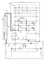
- a block diagram of a prior art safety relay combination type is in the system: "5983 BN" attached, in this block diagram, the shielding according to the invention is additionally located.
- 1 is the safety edge and 6 is the mounting edge shown for the safety edge 1, usually the mounting bar 6 is made of metal.
- the safety edge 1 lies above the mounting strip 6 the actual one Head 3, as known in the art.
- this conductor 3 is provided with a safety shield 5 surround, which ends at the earth potential of the Signal generator, d. H. according to the drawing on the fastening strip 6 of the safety edge 1 connects.
- the other end is that Safety shield 5 on a corresponding line the protective conductor connection PE (-) of the relay safety combination 2 connected, so that already at earth fault a shutdown of the supply or discharge of the closed circuit the load circuits is effected.
Landscapes
- Engineering & Computer Science (AREA)
- General Engineering & Computer Science (AREA)
- Mechanical Engineering (AREA)
- Emergency Protection Circuit Devices (AREA)
- Keying Circuit Devices (AREA)
- Testing Electric Properties And Detecting Electric Faults (AREA)
- Control Of Motors That Do Not Use Commutators (AREA)
- Power Conversion In General (AREA)
- Dc-Dc Converters (AREA)
Claims (2)
- Commutateur électrique avec une barre de commutation comme capteur de signaux qui conduit à une fonction de commutation en cas d'interruption d'un circuit à courant permanent, une combinaison de sécurité à relais (2) étant intégrée dans le circuit à courant permanent, caractérisé en ce que la ligne électrique du circuit à courant permanent qui arrive à la barre de commutation (1) et celle qui part de cette barre (3,4) sont respectivement entourées d'un blindage de sécurité conducteur (5) qui est raccordé d'un côté au potentiel de terre du capteur de signaux, par exemple à la barre de fixation (6) de la barre de commutation (1), et de l'autre côté au point de branchement du conducteur de protection (PE (-)) de la combinaison de sécurité à relais (2), le circuit de courant secondaire d'un transformateur étant relié unilatéralement avec les blindages de sécurité dans la combinaison de sécurité à relais.
- Commutateur électrique selon la revendication 1, caractérisé en ce que le capteur de signaux est réalisé en tant que barre de commutation (1) pour une protection des bords qui se touchent à la fermeture.
Applications Claiming Priority (3)
| Application Number | Priority Date | Filing Date | Title |
|---|---|---|---|
| DE19625752A DE19625752A1 (de) | 1996-06-27 | 1996-06-27 | Elektrische Schalteinrichtung mit einer Ruhestromüberwachung |
| DE19625752 | 1996-06-27 | ||
| PCT/DE1997/001349 WO1998000620A1 (fr) | 1996-06-27 | 1997-06-21 | Commutateur electrique a surveillance du courant permanent |
Publications (2)
| Publication Number | Publication Date |
|---|---|
| EP0906484A1 EP0906484A1 (fr) | 1999-04-07 |
| EP0906484B1 true EP0906484B1 (fr) | 2001-10-24 |
Family
ID=7798180
Family Applications (1)
| Application Number | Title | Priority Date | Filing Date |
|---|---|---|---|
| EP97931673A Expired - Lifetime EP0906484B1 (fr) | 1996-06-27 | 1997-06-21 | Commutateur electrique a surveillance du courant permanent |
Country Status (5)
| Country | Link |
|---|---|
| EP (1) | EP0906484B1 (fr) |
| AT (1) | ATE207574T1 (fr) |
| DE (2) | DE19625752A1 (fr) |
| ES (1) | ES2166550T3 (fr) |
| WO (1) | WO1998000620A1 (fr) |
Family Cites Families (5)
| Publication number | Priority date | Publication date | Assignee | Title |
|---|---|---|---|---|
| US3651332A (en) * | 1970-06-23 | 1972-03-21 | Kinnear Corp | Electrical control circuit for a door operator including an automatic control function for returning a door which is closing to an open position if an object is encountered |
| DE3606499C1 (de) * | 1986-02-28 | 1987-07-16 | Werner Haake | Schliesskanten-Sicherung |
| DE9006605U1 (de) * | 1990-06-12 | 1990-08-16 | Brinkmann, Heinz-Jürgen, 4322 Sprockhövel | Stromkreisüberwachung an bewegbaren Schließkanten |
| CA2059802C (fr) * | 1991-02-01 | 1997-12-02 | Dennis W. Waggamon | Detecteur d'erreur de cablage pour dispositif de fermeture de porte |
| IT1263649B (it) * | 1993-03-26 | 1996-08-27 | Clemente Possamai | Sistema di protezione di cavi ed apparecchi elettrici da guasti tendenti a provocare incendi mediante impiego di un conduttore di guardia per provocare l'intervento di interruttori differenziali ad alta sensibilita' |
-
1996
- 1996-06-27 DE DE19625752A patent/DE19625752A1/de not_active Withdrawn
-
1997
- 1997-06-21 WO PCT/DE1997/001349 patent/WO1998000620A1/fr not_active Ceased
- 1997-06-21 DE DE59705093T patent/DE59705093D1/de not_active Expired - Fee Related
- 1997-06-21 EP EP97931673A patent/EP0906484B1/fr not_active Expired - Lifetime
- 1997-06-21 ES ES97931673T patent/ES2166550T3/es not_active Expired - Lifetime
- 1997-06-21 AT AT97931673T patent/ATE207574T1/de not_active IP Right Cessation
Also Published As
| Publication number | Publication date |
|---|---|
| ES2166550T3 (es) | 2002-04-16 |
| WO1998000620A1 (fr) | 1998-01-08 |
| EP0906484A1 (fr) | 1999-04-07 |
| ATE207574T1 (de) | 2001-11-15 |
| DE19625752A1 (de) | 1998-01-02 |
| DE59705093D1 (de) | 2001-11-29 |
Similar Documents
| Publication | Publication Date | Title |
|---|---|---|
| EP3218230A1 (fr) | Réseau d'alimentation de vehicule automobile | |
| DE102007022401A1 (de) | Leistungsschalter für Störlichtbogenschutz | |
| DE20004593U1 (de) | Sammelschienensystem mit Überspannungsschutz | |
| EP2274760B1 (fr) | Circuit électrique comprenant un moyen de signalisation | |
| EP0906484B1 (fr) | Commutateur electrique a surveillance du courant permanent | |
| DE3632760A1 (de) | Schutzschaltungsanordnung | |
| EP0007626B1 (fr) | Circuit pour l'alimentation à distance des stations intermédiaires d'un dispositif utilisé dans la technique de transmission d'information | |
| EP1057194B1 (fr) | Dispositif de commutation electrique avec surveillance de courant de repos | |
| EP4439091A1 (fr) | Borne enfichable pour compteur, module et armoire de distribution | |
| DE102020118110A1 (de) | Überspannungsschutzanordnung | |
| DE3337276A1 (de) | Schaltfeld fuer eine mittelspannungs- oder niederspannungsschalt- und -verteileranlage | |
| DE4015301C2 (de) | Überspannungsschutzeinrichtung für elektrische Anlagen | |
| DE102014201503A1 (de) | Elektrische Schutzanordnung für eine Elektroinstallation sowie dazugehöriges Verfahren | |
| DE19702009C2 (de) | Überwachungseinrichtung mit Überwachungsschaltern | |
| DE3813403C2 (de) | Ortsveränderlicher Differenzstromschalter | |
| EP0889569A2 (fr) | Appareillage d'installation | |
| AT409193B (de) | Schaltungsanordnung | |
| EP3713021B1 (fr) | Appareil de protection contre les surtensions pourvu de prise de tension | |
| DE102019118951A1 (de) | Überspannungsschutzanordnung | |
| DE19516092B4 (de) | Gefahrenmeldeanlage mit wenigstens einer Schirmleitung | |
| DE10246479B4 (de) | Niederspannungs-Leistungsschalter mit zusätzlicher Schnellauslösung | |
| DE3012076A1 (de) | Anordnung zur ueberwachung des ch (pfeil abwaerts)4(pfeil abwaerts) -gehalts im freien querschnitt von grubenbetrieben | |
| DE102006061476B3 (de) | Elektrische Steuerung | |
| EP4622031A1 (fr) | Système de protection contre les arcs électriques parasites | |
| DE2429564C3 (de) | Prüfeinrichtung zur Feststellung von Schlüssen zwischen nebeneinander geführten Leitungen |
Legal Events
| Date | Code | Title | Description |
|---|---|---|---|
| PUAI | Public reference made under article 153(3) epc to a published international application that has entered the european phase |
Free format text: ORIGINAL CODE: 0009012 |
|
| 17P | Request for examination filed |
Effective date: 19980225 |
|
| AK | Designated contracting states |
Kind code of ref document: A1 Designated state(s): AT DE ES FR GB IT NL SE |
|
| GRAG | Despatch of communication of intention to grant |
Free format text: ORIGINAL CODE: EPIDOS AGRA |
|
| 17Q | First examination report despatched |
Effective date: 20010212 |
|
| GRAG | Despatch of communication of intention to grant |
Free format text: ORIGINAL CODE: EPIDOS AGRA |
|
| GRAH | Despatch of communication of intention to grant a patent |
Free format text: ORIGINAL CODE: EPIDOS IGRA |
|
| GRAH | Despatch of communication of intention to grant a patent |
Free format text: ORIGINAL CODE: EPIDOS IGRA |
|
| GRAA | (expected) grant |
Free format text: ORIGINAL CODE: 0009210 |
|
| AK | Designated contracting states |
Kind code of ref document: B1 Designated state(s): AT DE ES FR GB IT NL SE |
|
| REF | Corresponds to: |
Ref document number: 207574 Country of ref document: AT Date of ref document: 20011115 Kind code of ref document: T |
|
| REF | Corresponds to: |
Ref document number: 59705093 Country of ref document: DE Date of ref document: 20011129 |
|
| REG | Reference to a national code |
Ref country code: GB Ref legal event code: IF02 |
|
| ET | Fr: translation filed | ||
| GBT | Gb: translation of ep patent filed (gb section 77(6)(a)/1977) |
Effective date: 20020117 |
|
| REG | Reference to a national code |
Ref country code: ES Ref legal event code: FG2A Ref document number: 2166550 Country of ref document: ES Kind code of ref document: T3 |
|
| PLBE | No opposition filed within time limit |
Free format text: ORIGINAL CODE: 0009261 |
|
| STAA | Information on the status of an ep patent application or granted ep patent |
Free format text: STATUS: NO OPPOSITION FILED WITHIN TIME LIMIT |
|
| 26N | No opposition filed | ||
| PGFP | Annual fee paid to national office [announced via postgrant information from national office to epo] |
Ref country code: ES Payment date: 20030604 Year of fee payment: 7 |
|
| PGFP | Annual fee paid to national office [announced via postgrant information from national office to epo] |
Ref country code: GB Payment date: 20030611 Year of fee payment: 7 |
|
| PGFP | Annual fee paid to national office [announced via postgrant information from national office to epo] |
Ref country code: FR Payment date: 20030618 Year of fee payment: 7 |
|
| PGFP | Annual fee paid to national office [announced via postgrant information from national office to epo] |
Ref country code: AT Payment date: 20030626 Year of fee payment: 7 |
|
| PG25 | Lapsed in a contracting state [announced via postgrant information from national office to epo] |
Ref country code: GB Free format text: LAPSE BECAUSE OF NON-PAYMENT OF DUE FEES Effective date: 20040621 Ref country code: AT Free format text: LAPSE BECAUSE OF NON-PAYMENT OF DUE FEES Effective date: 20040621 |
|
| PG25 | Lapsed in a contracting state [announced via postgrant information from national office to epo] |
Ref country code: ES Free format text: LAPSE BECAUSE OF NON-PAYMENT OF DUE FEES Effective date: 20040622 |
|
| GBPC | Gb: european patent ceased through non-payment of renewal fee |
Effective date: 20040621 |
|
| PG25 | Lapsed in a contracting state [announced via postgrant information from national office to epo] |
Ref country code: FR Free format text: LAPSE BECAUSE OF NON-PAYMENT OF DUE FEES Effective date: 20050228 |
|
| REG | Reference to a national code |
Ref country code: FR Ref legal event code: ST |
|
| PG25 | Lapsed in a contracting state [announced via postgrant information from national office to epo] |
Ref country code: IT Free format text: LAPSE BECAUSE OF NON-PAYMENT OF DUE FEES;WARNING: LAPSES OF ITALIAN PATENTS WITH EFFECTIVE DATE BEFORE 2007 MAY HAVE OCCURRED AT ANY TIME BEFORE 2007. THE CORRECT EFFECTIVE DATE MAY BE DIFFERENT FROM THE ONE RECORDED. Effective date: 20050621 |
|
| REG | Reference to a national code |
Ref country code: ES Ref legal event code: FD2A Effective date: 20040622 |
|
| PGFP | Annual fee paid to national office [announced via postgrant information from national office to epo] |
Ref country code: NL Payment date: 20070618 Year of fee payment: 11 |
|
| PGFP | Annual fee paid to national office [announced via postgrant information from national office to epo] |
Ref country code: SE Payment date: 20070626 Year of fee payment: 11 |
|
| EUG | Se: european patent has lapsed | ||
| NLV4 | Nl: lapsed or anulled due to non-payment of the annual fee |
Effective date: 20090101 |
|
| PG25 | Lapsed in a contracting state [announced via postgrant information from national office to epo] |
Ref country code: NL Free format text: LAPSE BECAUSE OF NON-PAYMENT OF DUE FEES Effective date: 20090101 |
|
| PGFP | Annual fee paid to national office [announced via postgrant information from national office to epo] |
Ref country code: DE Payment date: 20090407 Year of fee payment: 13 |
|
| PG25 | Lapsed in a contracting state [announced via postgrant information from national office to epo] |
Ref country code: SE Free format text: LAPSE BECAUSE OF NON-PAYMENT OF DUE FEES Effective date: 20080622 |
|
| PG25 | Lapsed in a contracting state [announced via postgrant information from national office to epo] |
Ref country code: DE Free format text: LAPSE BECAUSE OF NON-PAYMENT OF DUE FEES Effective date: 20110101 |